panel JAGUAR X308 1998 2.G Workshop Manual
[x] Cancel search | Manufacturer: JAGUAR, Model Year: 1998, Model line: X308, Model: JAGUAR X308 1998 2.GPages: 2490, PDF Size: 69.81 MB
Page 2371 of 2490
Supplemental Restraint System - Air Bag Control Module
Removal and Installation
Removal
Installation
1.
WARNING: FOLLOWING DISCONNECTION OF THE
BATTERY, A PERIOD OF AT LEAST ONE MINUTE MUST BE
ALLOWED TO ELAPSE BEFORE ANY WORK IS CARRIED OUT ON
AN AIR BAG SYSTEM COMPONENT.
Remove battery cover and disc onnect ground cable from
battery terminal. Refer to 86.15.19.
2. Remove 'J' gate surroun d. Refer to 76.25.24.
3. Remove centre console veneer panel. Refer to 76.47.26.
4. Remove radio. Re fer to 86.50.03.
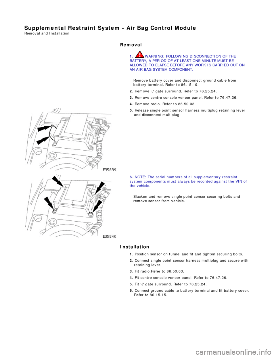
5. Release single point sensor ha rness multiplug retaining lever
and disconnect multiplug.
6. NOTE: The serial num bers of all supplementary restraint
system components must always be recorded against the VIN of
the vehicle.
Slacken and remove single point sensor securing bolts and
remove sensor from vehicle.
1. Position sensor on tunnel and fit and tighten securing bolts.
2. Connect single point sensor harn ess multiplug and secure with
retaining lever.
3. Fit radio.Refer to 86.50.03.
4. Fit centre console veneer panel. Refer to 76.47.26.
5. Fit 'J' gate surround. Refer to 76.25.24.
6. Connect ground cable to battery terminal and fit battery cover.
Refer to 86.15.15.
Page 2381 of 2490
The body is pre-treated to ensure high resistance to corrosion and stone chip dama ge. Prior to the first major pre-treatment process, the body shell is high-pressure washed to remove any metal dust and residual oil.
The first major pre-treatment process consists of phosphate and electro-paint deposition, which together with zinc coating,
forms the basis of the corrosion protection. This process includes high pressure knock-off, alkali de-greasing, zinc phosphate
conversion of body steel (dissolving iron and coating with zinc phosphate crystals), trivalent chrome rinsing and
demineralized water rinsing, seal ing all chemicals and impurities.
Both dip and spray techniques are employed and the bodies are submerged to the waistline during the first and third rinses
of the main phosphate clean. Chemical strengths and soluti on temperatures are continuously monitored and accurately
controlled throughout the process.
An 80% water primer is then cathodic elec tro-deposition applied to the thoroughly cleansed bodies in a uniform 'sag-free'
film 18 to 32 micron thick. Optimum durabi lity of the electroprimer is achieved by finally curing in a stoving oven at 165 °C
for a period of 20 minutes.
All underbody seams of the fully primed bo dies are then manually sealed, to prevent water and dust ingress into the vehicle
and to enhance corrosion protection.
An 800 to 1000 g/m2 PVC coating is semi-automatic airless sp ray applied to the underside of the main floor panels, trunk
floor and rear wheel arches (ref. illustration above).
The upper panels of primed and external ly sealed bodyshells are next lightly scuffed to remove imperfections and a PVC
coating is applied to all internal seams by an airless spray technique. A PVC bead seal is also applied to the doors, hood and
trunk clinch joints.
Following anti-corrosion, sealing and primin g treatment, the bodies enter the first stage of 'cosmetic' painting. This consists
of the application of two coats of a highly chip resistant po lyester surfacer, employing high voltage electrostatic 'spinning
bells', to achieve a final film thickness of 35 to 50 micron. Between surfacer coats, a polyurethane coat is automatically
applied to the sills to impart even greater resistance to stone chipping.
All interior panels are then painted us ing a color keyed sealer, wet-on-wet wi th a surfacer material, after which the
bodyshells are stoved at 160 °C for a period of 20 minutes. Further protection agai nst corrosion is provided by a medium
solids black pigmented wax which is airless spray applied to vehicle undersides.
Wax Injected Box Sections
Critical body box-sections are si milarly protected by spray injecting a high solids wax. This is then re-flowed at 70 to 90 °C
to achieve optimum seam/joint penetratio n and form a resilient and durable internal coating (ref. illustration above).
After full wet sanding, rinsing and drying to provide a good su bstrate, a color-keyed semi-matt sealer co at is applied using
electrostatic bells to achieve a film build of 25 to 35 micron . The bodies are then stoved for a further 20 minutes at a
temperature of 145 °C and subjected to a local 'seek-and-find' de -nib operation prior to the final two coat process. The final
top coat finish is achieved by using poly ester base coat colors and an acrylic sag resistant clear coat. This clear over base
(COB) process produces a high gloss, durabl e paint finish with a film thickness of 50 to 65 micron, which is finally cured at a
temperature of 135°C for 20 minutes.
The Munsell three dimensional system of color management is em ployed to achieve highly accurate control of vehicle colors.
This system ensures that paint pigmentations are accurately maintained and facilitates vigorous final checking of finished
vehicles for color match. The hu e of individual panels such as trunk lids, doors and hoods is in some instances adjusted to
offset the effects of differing light angles. Where applicable, coachlines are manually applied and radiant heat cured on the
completed and valeted vehicle prior to hand spray applic ation of a protective wax coat.
Introduction
All repairs, whether structural or cosmetic must return the vehicle to the original manufactured condition with regard to
occupant safety, dimensional accuracy, fi nish and corrosion protection, and ensure continuation of the Paint Surface and
Corrosion warranty where applicable.
Similarly, repaired vehicles must be fu lly checked, and where appropriate reset, with regard to steering, suspension,
braking, and occupant restraint systems.
Page 2382 of 2490
Health and Safety
It is the duty of both employer and employee to ensure safe working conditions and practices. Correct safety procedures
and equipment must be applied to any potential hazards that are notified, or identified by an operator.
Employees must observe local legislation go verning working conditions and practices at all times and must always act in a
responsible manner in the workplace. In the event of personal injury resulting from any workshop activity, medical help
should be obtained as soon as poss ible. Self-treatment other than by first aid, should not be attempted.
WARNING: READ AND UNDERSTAND WORKING PRACTICE S CONCERNING CLIMATE CONTROL SYSTEMS, SECTION
412, WITH SPECIAL REGARD TO: REFRIGERANT MUST NEVE R BE DIRECTLY VENTED TO ATMOSPHERE. ALWAYS USE
JAGUAR APPROVED RECOVERY / RECYCLE / RECHARGE EQUI PMENT, WEAR SUITABLE EYE AND SKIN PROTECTION AND
OBSERVE ALL APPLICABLE SAFETY REQUIREMENTS.
With the constant introduction of new materials in the manufacture of vehicles, an awareness of the potential risks and
appropriate precauti ons is important.
Notification of Hazards
Symbols, which convey important information, will be positioned at the beginning of any specific operation or text. Standard symbols will be used where repairs or service procedures ar e detailed. All symbols will conform to standard ANSI Z535.3
(American National Standards Institute). The surround shape of the symbol will indicate the basis of the message to be
conveyed (see top three elements of ?) The icon depicting the message will be within the surrounding shape. Once
nominated the icon will retain its meaning.
POTENTIAL RISKS
Paint
Organic solvents, found in paints, may caus e damage or severe irritation to liver, kidneys, digestive tracts and respiratory
system if inhaled over long pe riods of time. Prolonged exposure to isocyanate s can cause lung sensitization with asthma-like symptoms developing on subsequent exposure to even low concentrations of isocyanates. Solvent inhalation can cause
dizziness or loss of consciousness and inhalation of spray dust and sanding debris may cause lung damage.
Spillage or splashes of solvents, paint ac tivators and additives can cause dermatitis or eye injury. Contact with peroxide or
acid catalysts can cause serious burns.
Applied Heat (Welding)
There is considerable risk of damage to eyes and skin if welding or flame cutting is attempted without using the correct
protective equipment. Many materials or fluids within vehicles are highly flammable and toxic and dangerous fumes may
also be liberated if heat is applied to expanded foam, corr osion protection, trim and seat materials, paints containing
isocyanates, and adhesive and sealing compounds.
When heated to a temperature of 300°C, polyurethane based compounds may liberate small quantities of isocyanate. Many
types of nitrogen containing chemicals ma y be liberated as breakdown products which can contain isocyanates, oxides of
nitrogen and hydrogen cyanide.
Potentially toxic or asphyxiant fumes and gases produced when welding include zinc oxide from zinc coated panels, and
ozone gas from the MIG process.
Metal Repair
There is considerable risk of damage to eyes, ears and skin wh en cutting, forming, or dressing metal. Soldering operations
can also be hazardous due to heat generated fumes and the risk of skin contact with hot materials.
PRECAUTIONS
Page 2383 of 2490
Paint
The inhalation of sprays, fumes, or dust during paint application or sanding processes should always be avoided. Ensure
that there is efficient ventilation / extrac tion at all times. Paint spraying should be confined as far as possible to spray
booths. Personnel with a history of asth ma should not be employed in any process involving the use of isocyanates.
Operators working in a spray booth where isocyanate material is present must use air-fed breathing equipment with air
supplied to the visor at the re commended pressure and filtered to remove oil, water, and fumes. Operators involved in
handling mixing or spraying should wear protective clothing including gloves and goggles, to avoid skin and eye contact.
Particle masks or canister type respir atosr should be worn when sanding.
Applied Heat
When welding, flame cutting, brazing etc, the operator shou ld use as appropriate, goggles, mask / fume extractor and
flameproof protective clothing. It is especially important when working with polyurethane compounds to use air-fed
breathing equipment. Appropriat e fire fighting equipment and personnel trai ned in its use must always be available.
Metal Repair
Appropriate eye and hand protection should be worn when sanding, drilling, cutting, chiselling, flatting or welding. Face
masks or air-fed visors should also be wo rn when sanding or flatting either body solder or fillers. On completion of a
soldering operation, swarf must be re moved from the work area and the operat or must wash his hands thoroughly.
GENERAL REPAIR NOTES
The following advice should be noted before any repair work is carried out.
Disconnect the vehicle battery gr ound lead (disconnect the alternator where electric welding is used) and take note of the
reconnection procedures as detailed in 86.15.15.
Where structural parts are straightened or renewed, a body alignment / straightening jig must be used. The application of
heat, especially excessive heat, reduces the strength of steels, where appropriate therefore, structural sections should be
straightened by cold processes.
Repairs may only be carried out successful ly, and any warranties protected, if genuine Jaguar replacement parts and Jaguar
approved materials are used.
The correct tools, procedures and facilities must always be us ed. The quality of the work must not be compromised by using
inappropriate methods or equipment.
All trim and electrical components in the locality of the repair must be removed or disconnected prior to panel removal /
replacement; this is especially important where hollow sectio ns may contain harnesses, tubes or foam, see section A4.3.5.
WARNING: DO NOT WORK IN THE VICINITY OF A LIVE AIR BAG, REMOVE IT COMPLETELY. READ WORKING
PRACTICES AIR BAG, SECTION 20. ANY SEAT BELT WHICH HAS BEEN WORN IN AN ACCIDENT MUST BE RENEWED.
CAUTION: Electric arc welding should not be used on Jaguar vehicles. The high voltages produced by this process will
cause irreparable damage to the electric al control and microprocessor systems.
The following welding and gas processes are the only ones recommended by Jaguar Cars Ltd.
Welding and Gas Processes
Resistance spot welding, MIG welding and all gas processes may only be carried out on bare, unpainted or unplated metal.
The flanges of panels to be welded toge ther, must be clean, corrosion free and tr eated as appropriate, with either weld-
through primer or inter-weld sealer. Only materials and processes specified in the 'Body Sealing and Preservation Manual'
should be used in the relevant application areas detailed in this section. Refer to 'Zinc Coated Panels' Section
Page 2384 of 2490
Generally, resistance spot welding equipment used in the motor vehicle repair industry does not produce welds of equivalent strength to those achieved during manufactu re. The expression 'single row of resistance spot welds' indicates that the spots
should be spaced on a pitch of 19mm to 25mm, which normally results in mo re spot welds than those produced in the
original factory joint.
Resistance spot welds should be removed using a resistance spot weld cutter. If the new joint is to be MIG plug welded, old
resistance spot welds should be cut from the panel to be reta ined and the resulting holes used for plug welding. Suitable
holes may also be drilled or punched; 8,0 mm dia for sect ions up to 1,6 mm, and 10,0 mm dia for thicker sections.
PLASTICS-EXPLANATORY NOTES
Plastic component and trim materials
This table, in conjunction with the illu strations on the following pages will enable rapid identification of the particular
material of any major plastic part.
• NOTE: Only those components suitable for economic reclamation are identified.
Plastics - Handling Notes
The exterior panel temperature of a vehicle must not exceed 95°C at any time and may only be held at this level for a
maximum of two hours. Similarly, interior vehicle temperatur e must be limited to 86°C for a maximum duration of two
hours. Exposure to temperatures above those specified may result in distorted or permanently damaged components. If
there is doubt concerning temperature limitations, components that may be adversel y affected by exposure to heat should
be removed from the vehicle.
Plastic components that become greasy may be clea ned with an 'SBP 3' spirit wipe, or equivalent.
Recycled Materials
Any of the materials listed in this section, may be recycled provided that they ar e not contaminated by other incompatible
plastics or metals. For instan ce, the air conditioning unit case, manufactur ed from PP (polypropylene), must be separated
from the heater matrix, evaporator, contro l devices (electronic and mechanical) and all fixings before it can be considered
for recycling. After removal, the case mu st only be placed for disposal with materials of the same generic type. Bumper
cover assemblies similarly have side arma tures of dissimilar materials rivetted to them, these together with their fixings
must be removed prior to recy cling. Components manufactured from 'blended' materials must not be recycled with pure
materials. For example do not mix PC/ABS (wheel trim) with ABS ('B' pillar upper trim).
Plastics, Component Location and Type - External
TermMaterial Name
absAcrylonitrile Butadiene Styrene
abs / paAcrylonitrile Butadiene Styrene and Polyamide (nylon) blend
abs / pcAcrylonitrile Butadiene Styrene and Polycarbonate blend
ABS / PBTAcrylonitrile Styrene Acrylate and Polybutylene Terephthalate
paPolyamide (nylon)
pcPolycarbonate
pePolyethylene
pmmaPolymethyl Methacrylate
pomPolyoxymethylene (acetal)
ppPolypropylene
ppoModified Polyphenylene Oxide
purPolyurethane
pvcPolyvinylchloride
SMAStyrene Maleic Anhydride
Page 2386 of 2490
Body Structure
Introduction
The standard wheelbase Jaguar sedan has a unit construction monocoque body structure with bolt-on front fenders and
welded rear fenders. The doors feature lif t-off hinges and welded drop-glass frames.
Constructional Steel Classification
BODY ALIGNMENT
The Body Dimensions Plan, and Body Dimensions Side View, provide specified BIW dimensions to facilitate damage
assessment and location of replacemen t parts. These dimensions must be strictly applied when used for damage
assessment, component location or post repair verification.
• NOTE: The right-hand side is always looking towards the front, from the rear of the vehicle.
The nominated plan view master datums are on the right-hand side of the body with the left-hand datums dimensioned
from them. Right-hand datums must therefore be known to be correct before any other cross-car dimensions are checked.
Datum location, Example
The Front Master Datum (front crossmember rear mounting at the inner face of the main floor RH longitudinal) is nominally
359,5mm to the right-hand side of the body center line. The LH side fron t datum is measured 717,0 / 721,0mm from the
RH. Refer to the Body Dimensions Plan.
Expressed as a true posi tion in three planes, the front master datum is:
Standard Wheelbase Bo dy Dimensions-Plan
MaterialApplication
High strength low alloy
(HLSA).Impact prone areas, ie. seat frame and bumper mountings.
Double sided zinc plated mild steel.Exterior body panels subject to severe cond itions such as stone chipping and weather
exposure (excluding roof panel).
Boron steelDoor intrusion beams
Mild steel.Internal brackets, fill ets and strengtheners.
DatumLocationPosition
Front Master Datum
PlanCentre line of the front crossmember rear mounting, at the main floor RH
longitudinalX
300,0
Y 359,5 Z -50,0
Page 2391 of 2490
ZINC COATED PANELS
Description
Approximately 70% of the 'body in white' (BIW) mass is made up of zinc coated panels.
• NOTE: To maintain the protective qualities of the zinc trea tment, repairs to any damaged coated area must be made as
soon as possible after the damage has occurred.
All exterior skin panels, with the exceptio n of the roof, are double side zinc plated and this coating (nominally 7,5 microns)
provides two way corrosion protection. Should the outer layer of paint become chipped with the zinc coating remain intact,
the zinc will oxidize on contact with air and being impermeable, this coat of oxidation will prevent corrosion damage of the
base metal. If the outer layer of paint and the zinc coating become damaged, the zinc rather than the base metal will react
with the air and 'sacrifice' itself to corrosion as a 'sacrificial anode'.
Welding Preparation
Contamination of the weld with resultant reduction in joint st rength increase and increased electrode tip dressing frequency
will occur zinc coating is not removed. In exceptional cases where the zinc coating must remain intact, the tip pressure and
welding current should be increased by 10 to 20%.
Where 'resistance spot welding' is employed, the zinc coatin g should be lightly abraded away on the mating surfaces and
those in contact with the electrode tips. Do not remove more zinc coating than is absolutely necessary.
Before welding, a weld-through primer or inter-weld sealer should be applied, as detailed in the Body Sealing and
Preservation manual.
Where MIG welding is used as an alternativ e to resistance spot welding for plug and butt welds or due to limited access, the
problems caused by the presence of zinc coating are much the same, with the added complication of increased weld spatter
and nozzle contamination.
Body Fillers
Conventional polyester fillers do not adhere satisfactorily to zinc plated panels, it is ther efore important that only those
products specifically designed for this application are used and the manufacturer's recommendations are followed.
Refinishing
Use only those products approved by Jaguar Cars Ltd and exercise special care on zinc coated panels.
As replacement panels ar e supplied ready primed, the only bare metal that needs to be exposed are those areas prepared
for welding etc, as decribed in 'Welding Preparation. Where any part of a panel is dressed back to the bare surface, it should
be treated with a zinc rich primer compatible with the paint application system.
GENERAL PREPARATION OF PANELS
Removal of Panels and Welds
• NOTE: Where other components must be removed for access, refer to the relevant manual section for guidance. This is
particularly important where steerin g, braking, suspension, electrical and safety systems are affected.
Expose all resistance spot welds, using a ro tary wire brush fitted to an air drill or a hand held wire brush on those that are
not clearly visible (1).
WARNING: DO NOT BURN UNDERSEAL OFF. USE A 'HOT KNIFE' OR SUITABLE SOLVENT.
Cut out spot welds using a Zipcutter or Roto-Bor (2). At this point it may be necessary to cut out the bulk of the panel using
Page 2392 of 2490
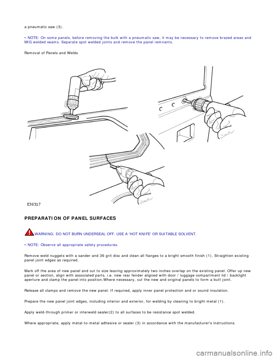
a pneumatic saw (3).
• NOTE: On some panels, before removing the bulk with a pneumatic saw, it may be necessary to remove brazed areas and
MIG welded seams. Separate spot welded joints and remove the panel remnants.
Removal of Panels and Welds
PREPARATION OF PANEL SURFACES
WARNING: DO NOT BURN UNDERSEAL OFF. USE A 'HOT KNIFE' OR SUITABLE SOLVENT.
• NOTE: Observe all appropriate safety procedures.
Remove weld nuggets with a sander and 36 gr it disc and clean all flanges to a bright smooth finish (1). Straighten existing
panel joint edges as required.
Mark off the area of new panel and cut to size leaving approxim ately two inches overlap on the existing panel. Offer up new
panel or section, align with associated pa rts, i.e. new rear fender aligned with door / luggage compartment lid / backlight
aperture and clamp the panel into positi on.Where necessary, cut the new and orig inal panels to form a butt joint.
Release all clamps and remove the new panel. If required, apply inner panel protection and or sound insulation.
Prepare the new panel joint edges, including interior and exterior, for welding by cleaning to bright metal (1).
Apply weld-through primer or in terweld sealer(2) to all surfaces to be resistance spot welded.
Where appropriate, apply metal- to-metal adhesive or sealer (3) in accordance with the manufacturer's instructions.
Page 2393 of 2490
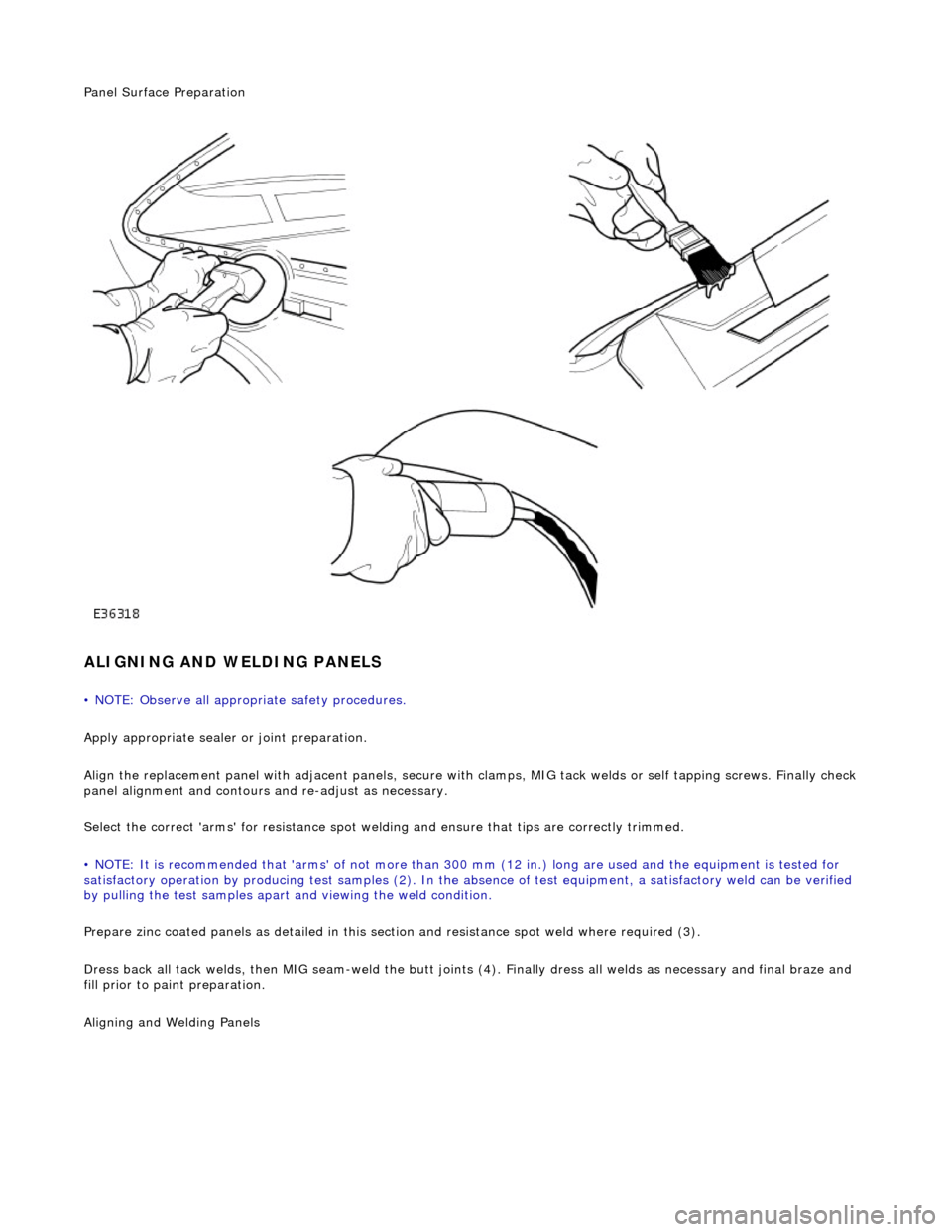
Panel Surface Preparation
ALIGNING AND WELDING PANELS
• NOTE: Observe all appropriate safety procedures.
Apply appropriate sealer or joint preparation.
Align the replacement panel with adjacent panels, secure with clamps, MIG tack welds or self tapping screws. Finally check
panel alignment and contours and re-adjust as necessary.
Select the correct 'arms' for resistance spot welding and ensure that tips are correctly trimmed.
• NOTE: It is recommended that 'arms' of not more than 300 mm (12 in.) long ar e used and the equipment is tested for
satisfactory operation by producing test samples (2). In the ab sence of test equipment, a satisfactory weld can be verified
by pulling the test sa mples apart and viewing the weld condition.
Prepare zinc coated panels as detailed in this section and resistance spot weld where required (3).
Dress back all tack welds, then MIG seam-weld the butt joints (4). Finally dress all welds as necessary and final braze and
fill prior to paint preparation.
Ali
gning and Welding Panels
Page 2403 of 2490
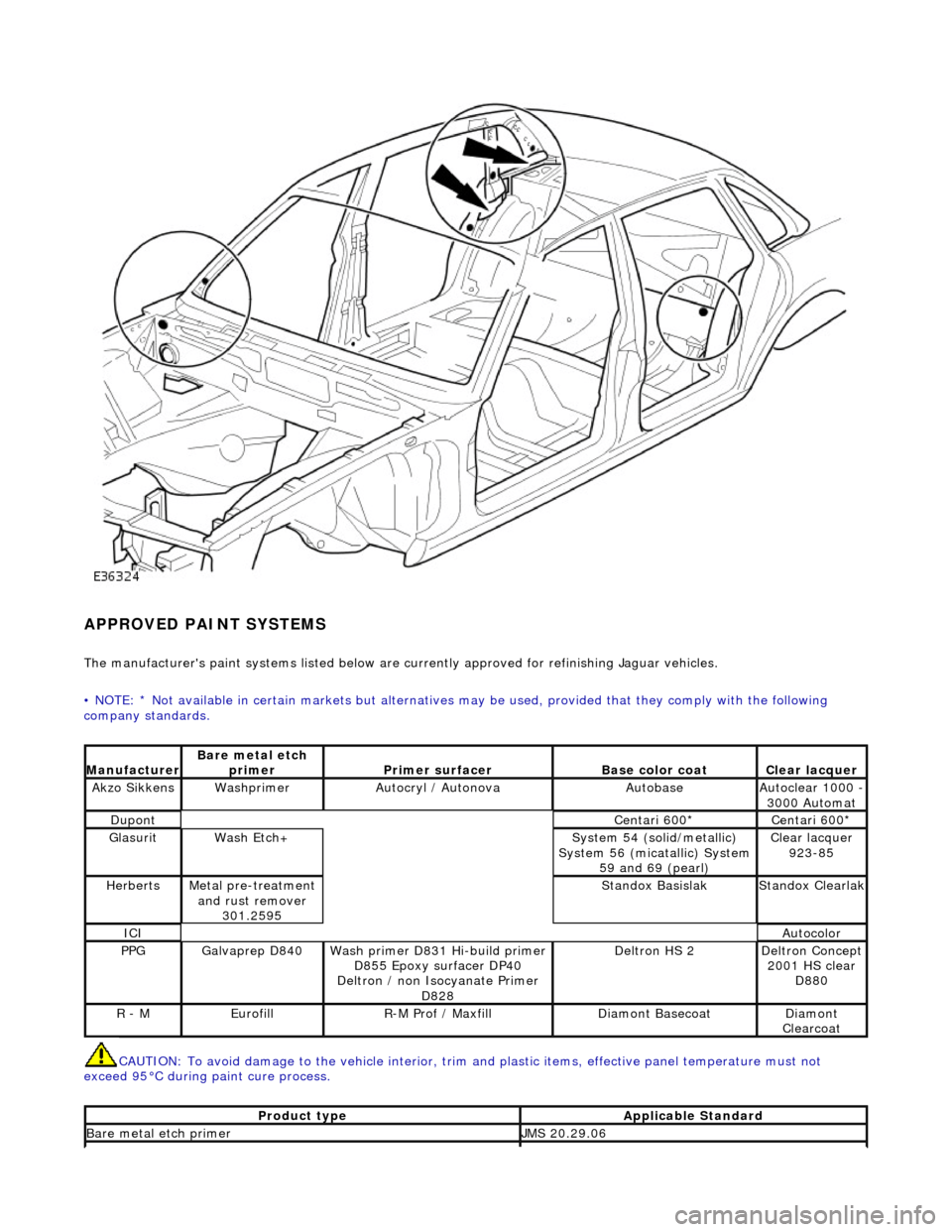
APPROVED PAINT SYSTEMS
The manufacturer's paint systems listed below are currently approved for refinishing Jaguar vehicles.
• NOTE: * Not available in certain market s but alternatives may be used, provided that they comply with the following
company standards.
CAUTION: To avoid damage to the vehi cle interior, trim and plastic items, effective panel temperature must not
exceed 95°C during paint cure process.
ManufacturerBare metal etch primerPrimer surfacerBase color coatClear lacquer
Akzo SikkensWashprimerAutocryl / AutonovaAutobaseAutoclear 1000 - 3000 Automat
DupontCentari 600*Centari 600*
GlasuritWash Etch+System 54 (solid/metallic)
System 56 (micatallic) System 59 and 69 (pearl)Clear lacquer 923-85
HerbertsMetal pre-treatment and rust remover 301.2595Standox BasislakStandox Clearlak
ICIAutocolor
PPGGalvaprep D840Wash primer D831 Hi-build primer D855 Epoxy surfacer DP40
Deltron / non Isocyanate Primer D828Deltron HS 2Deltron Concept 2001 HS clear D880
R - MEurofillR-M Prof / MaxfillDiamont BasecoatDiamont
Clearcoat
Product typeApplicable Standard
Bare metal etch primerJMS 20.29.06