low beam JAGUAR X308 1998 2.G Workshop Manual
[x] Cancel search | Manufacturer: JAGUAR, Model Year: 1998, Model line: X308, Model: JAGUAR X308 1998 2.GPages: 2490, PDF Size: 69.81 MB
Page 25 of 2490
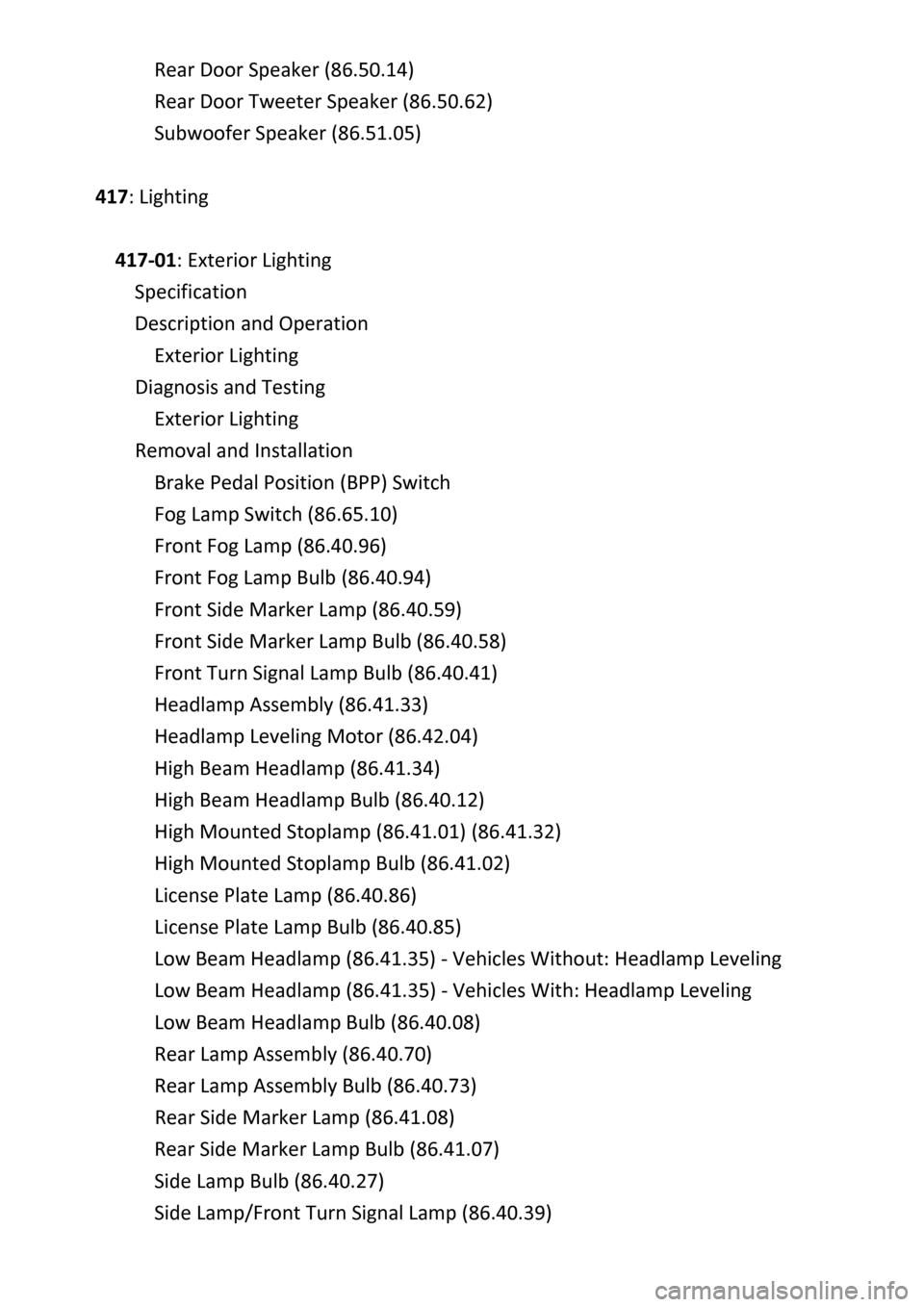
Rear Door Speaker (86.50.14)
Rear Door Tweeter Speaker (86.50.62)
Subwoofer
Speaker (86.51.05)
417: Lighting
417‐01: Exterior Lighting
Specification
Description and Operation
Exterior Lighting
Diagnosis and Testing
Exterior Lighting
Removal and Installation
Brake Pedal Position (BPP) Switch
Fog Lamp Switch (86.65.10)
Front Fog Lamp (86.
40.96)
Front Fog Lamp Bulb (86.40.94)
Front Side Marker Lamp (86.40.59)
Front Side Marker Lamp Bulb (86.40.58)
Front Turn Signal Lamp Bulb (86.40.41)
Headlamp Assembly (86.41.33)
Headlamp Leveling Motor (86.42.04)
High Beam Headlamp (86.41.34)
High Beam Headlamp Bulb (86.40.12)
High Mounted Stoplamp (86.41.01) (86.41.32)
High Mo
unted Stoplamp Bulb (86.41.02)
License Plate Lamp (86.40.86)
License Plate Lamp Bulb (86.40.85)
Low Beam Headlamp (86.41.35) ‐ Vehicles Without: Headlamp Leveling
Low Beam Headlamp (86.41.35) ‐ Vehicles With: Headlamp Leveling
Low Beam Headlamp Bulb (86.40.08)
Rear Lamp Assembly (86.40.70)
Rear Lamp Assembly Bulb (86.40.73)
Rear Side Marker La
mp (86.41.08)
Rear Side Marker Lamp Bulb (86.41.07)
Side Lamp Bulb (86.40.27)
Side Lamp/Front Turn Signal Lamp (86.40.39)
Page 54 of 2490
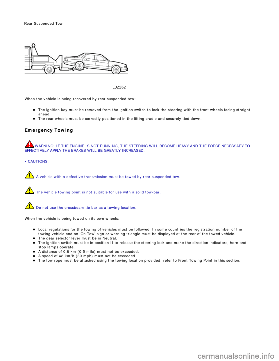
Wh en t
he vehicle is being reco
vered by rear suspended tow:
The ignition key must be remo ved from the ig
nition switch to lock the stee
ring with the front wheels facing straight
ahead.
The re ar
wheels must be
correctly positioned in the lifting cradle and securely tied down.
Em
ergency Towing
WARNING: IF THE
ENGINE IS NOT
RUNNING, THE STEERING WILL BECOME HEAVY AND THE FORCE NECESSARY TO
EFFECTIVELY APPLY THE BRAKES WILL BE GREATLY INCREASED.
• CAUTIONS:
A vehicle with a defective transmission must be towed by rear suspended tow.
The vehicle towing point is not suit able for use with a solid tow-bar.
Do not use the crossbeam tie bar as a towing location.
When the vehicle is being towed on its own wheels:
Loc a
l regulations for the towing of ve
hicles must be followed. In some co untries the registration number of the
towing vehicle and an 'On Tow' sign or warning triangle must be displayed at the rear of the towed vehicle.
The gear s
elector lever
must be in Neutral.
The
ignition switch must be in positi
on II to release the steering lock and make the direction indicators, horn and
stop lamps operate.
A di
stance of 0.8 km (0.5 mi
le) must not be exceeded.
A spe
ed of 48 km/h (30 mph) must not be exceeded.
The tow rope must be attached using th
e towi
ng location provided; refer to Front Towing Point in this section.
Rear Su
spended
Tow
Page 61 of 2490
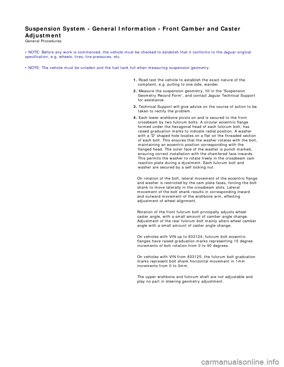
Suspension System - General Information - Front Camber and Caster
Adjust
ment
Gen
eral Procedures
• NOTE: Before any work is commenced, th e vehicle must be checked to establish that it conforms to the Jaguar original
specification, e.g. wheels, ti res, tire pressures, etc.
• NOTE: The vehicle must be unladen and the fuel tank full when measuring suspension geometry.
1.
Road test the vehicle to establish the exact nature of the
complaint, e.g. pulling to one side, wander.
2. Measure the suspension geometry, fill in the 'Suspension
Geometry Record Form', and co ntact Jaguar Technical Support
for assistance.
3. Technical Support will give advice on the course of action to be
taken to rectify the problem.
4. Each lower wishbone pivots on and is secured to the front
crossbeam by two fulcrum bolts. A circular eccentric flange
formed under the hexagonal head of each fulcrum bolt, has
raised graduation marks to indicate radial position. A washer
with a 'D' shaped hole locates on a flat on the threaded section
of each bolt. This ensures that the washer rotates with the bolt,
maintaining an eccentric position corresponding with the
flanged head. The outer face of the washer is punch marked,
ensuring correct instal lation with the chamfered face inwards.
This permits the washer to rotate freely in the crossbeam cam
reaction plate during a djustm ent. Each fulcrum bolt and
washer are secured by a self locking nut.
On rotation of the bolt, lateral movement of the eccentric flange
and washer is restricted by the cam plate faces, forcing the bolt
shank to move laterally in the crossbeam slots. Lateral
movement of the bolt shank re sults in corresponding inward
and outward movement of th e wishbone arm, effecting
adjustment of wh eel alignment.
Rotation of the front fulcrum bolt principally adjusts wheel
caster angle, with a small amount of camber angle change.
Adjustment of the rear fulcrum bo lt mainly alters wheel camber
angle with a small amount of caster angle change.
On vehicles with VIN up to 833124, fulcrum bolt eccentric
flanges have raised graduation marks representing 15 degree
increments of bolt rotati on from 0 to 90 degrees.
On vehicles with VIN from 833125, the fulcrum bolt graduation
marks represent bolt shank ho rizontal movement in 1mm
increments from 0 to 3mm.
The upper wishbone and fulcrum shaft are not adjustable and
play no part in steering geometry adjustment.
Page 67 of 2490
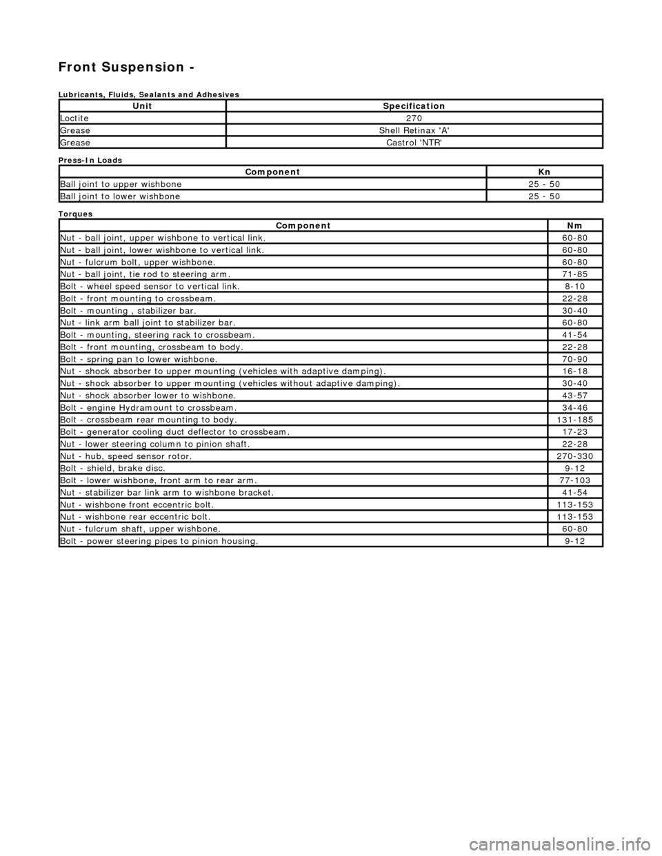
Front Suspension -
Lubri
cants, Fluids, Sealants and Adhesives
Press-In Loads
Torques
UnitS
pecification
Loctite27
0
Greas
e
Shell Retin
ax 'A'
Greas
e
Castro
l 'NTR'
Com
ponent
Kn
Ball join
t to upper wishbone
25
- 50
B
all joint to lower wishbone
25
- 50
Com
ponent
Nm
N
ut - ball joint, upper wishbone to vertical link.
60
-80
N
ut - ball joint, lower wishbone to vertical link.
60
-80
Nu
t - fulcrum bolt, upper wishbone.
60
-80
N
ut - ball joint, tie rod to steering arm.
71
-85
Bol
t - wheel speed sensor to vertical link.
8-1
0
Bol
t - front mounting to crossbeam.
22
-28
Bolt
- mounting , stabilizer bar.
30
-40
N
ut - link arm ball joint to stabilizer bar.
60
-80
Bolt
- mounting, steering rack to crossbeam.
41
-54
B
olt - front mounting, crossbeam to body.
22
-28
Bol
t - spring pan to lower wishbone.
70
-90
N
ut - shock absorber to upper mounting
(vehicles with adaptive damping).
16
-18
Nu
t - shock absorber to upper mounting (vehicles without adaptive damping).
30
-40
N
ut - shock absorber lower to wishbone.
43
-57
B
olt - engine Hydramount to crossbeam.
34
-46
B
olt - crossbeam rear mounting to body.
13
1-185
Bol
t - generator cooling du
ct deflector to crossbeam.
17
-23
N
ut - lower steering column to pinion shaft.
22
-28
N
ut - hub, speed sensor rotor.
27
0-330
B
olt - shield, brake disc.
9-1
2
Bol
t - lower wishbone, front arm to rear arm.
77
-103
Nu
t - stabilizer bar link arm to wishbone bracket.
41
-54
N
ut - wishbone front
eccentric bolt.
11
3-153
Nu
t - wishbone rear
eccentric bolt.
11
3-153
N
ut - fulcrum shaft, upper wishbone.
60
-80
Bolt -
power steering pi
pes to pinion housing.
9-1
2
Page 69 of 2490
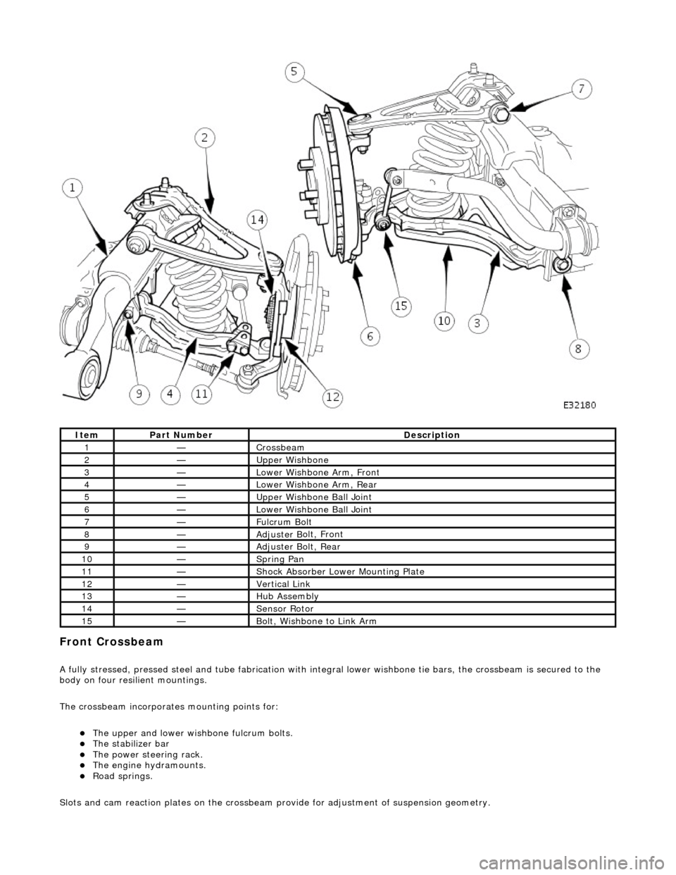
Front C
rossbeam
A
fully stressed, pressed steel and tube fa
brication with integral lower wishbone tie bars, the crossbeam is secured to the
body on four resilient mountings.
The crossbeam incorporates mounting points for:
The u
pper and lower wish
bone fulcrum bolts.
The
stabilizer bar
The power steering rack. The engine h
ydramounts.
R
oad springs.
Slots and cam reaction pl ates on the crossbeam provide for ad justment of suspension geometry.
It
em
Par
t Number
De
scription
1—Cro
ssbeam
2—Upper
Wishbone
3—Lower Wi
shbone Arm, Front
4—Lower Wi
shbone Arm, Rear
5—Upper
Wishbone Ball Joint
6—Lower Wi
shbone Ball Joint
7—Ful
crum Bolt
8—Adjuster B
olt, Front
9—Adjuster B
olt, Rear
10—S
pring Pan
11—Shock Absorber Lower M
ounting Plate
12—Vertical Link
13—Hub Assembly
14—Sensor R
otor
15—B
olt, Wishbone to Link Arm
Page 70 of 2490
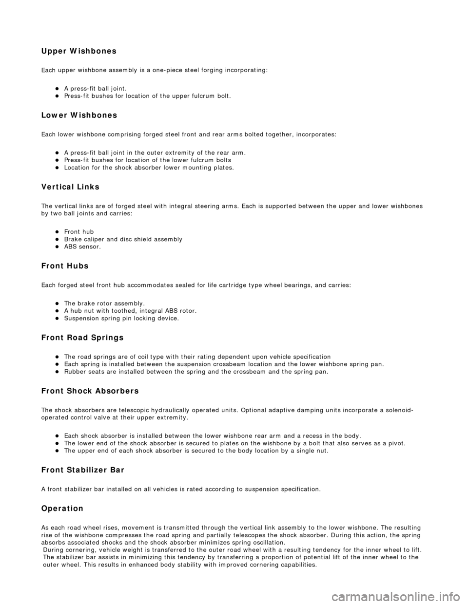
Upper
Wishbones
Each
upper wi
shbone assembly is a on
e-piece steel forging incorporating:
A pres
s-fit ball joint.
Press-fi
t bushes for location of the upper fulcrum bolt.
Lower Wishbones
Each l
o
wer wishbone comprising
forged steel front and rear arms bolted together, incorporates:
A p
ress-fit ball joint in the outer extremity of the rear arm.
Press-f
i
t bushes for location of the lower fulcrum bolts
Locati
on for the shock absor
b
er lower mounting plates.
Vertica l Links
The vertical
links are of forged steel
wi
th integral steering arms. Each is suppo rted between the upper and lower wishbones
by two ball joints and carries:
Front hub
Brake ca
liper and disc shield assembly
ABS se
nsor
.
Front Hub
s
Each f
o
rged steel front hub accommodates sealed for life cartridge
type wheel bearings, and carries:
The brake rotor assembl
y.
A
h
ub nut with toothed, integral ABS rotor.
Su
s
pension spring pi
n locking device.
Front Road
Springs
The road spri
ng
s are of coil type with their
rating dependent upon vehicle specification
Ea
ch spring is installed between the suspension crossbeam location and the lower wishbone spring pan.
Ru
bber seats ar
e installed betw
een the spring and the crossb eam and the spring pan.
Front Shock A
bsorbers
Th
e
shock absorbers are telescopic hydrau
lically operated units. Optional adaptive damping units incorporate a solenoid-
operated control valve at their upper extremity.
Each shoc
k absorber is installed between the lowe
r wishbone rear arm and a recess in the body.
The l
o
wer end of the shock absorber is se
cured to plates on the wishbone by a bolt that also serves as a pivot.
The u
pper en
d of each shock absorber is secured to the body location by a single nut.
Front Sta
b
ilizer Bar
A
front stabil
izer bar installed on all vehicles
is rated according to suspension specification.
Opera
tion
As each road wheel r
i
ses, move
ment is transmitted through the vertical link assembly to the lower wishbone. The resulting
rise of the wishbone compresses the road spring and partially telescopes the shock absorber. During this action, the spring
absorbs associated shocks and the shock absorber minimizes sprin
g os c
illation.
Du
ring cornering, vehicle weight
is transferred to the outer road wheel with a resulting tendency for the inner wheel to lift.
The stabilizer bar assists in minimizing this tendency by transf erring a proportion of potential lift of the inner wheel to the
outer wheel. This result s in enhanced body stability with improved corner ing capabilities.
Page 84 of 2490

In
stallation
Re
move steering rack securing bolts.
Carefully move steer
ing rack
downwards for access to
wishbone eccentric bolt.
29 . R
emove lower wishbone rear
arm eccentric bolt and nut.
Mark position of eccentri
c bo
lt large graduation mark on
crossbeam.
R e
move wishbone rear ec
centric bolt and nut.
30. Remove lower wishbone rear arm/ball joint assembly from
crossbeam.
1. Positi
on wishbone rear arm on crossbeam and install but do
not tighten eccentric bolt.
2. Install steeri
ng rack on crossbeam.
Ensure
that b
ushes are correct
ly positioned on steering
rack.
Posi ti
on steering rack on crossbeam.
Position support brac
kets over bus
hes.
Install mountin
g bracket bolts an
d tighten to 41-54Nm.
3. Install lower steering column on pinion shaft.
Move col u
mn downwards to engage coupling splines on
pinion shaft.
Page 96 of 2490

28. CAU
TION: Do not allow steerin
g pipes to support weight
of steering rack.
Position steering rack for access.
Pivot steering arm ful
ly downwards
Re
move steering rack securing bolts.
Carefully move steer
ing rack
downwards for access to
wishbone eccentric bolt.
29 . R
emove lower wishbone rear
arm eccentric bolt and nut.
Mark position of eccentri
c bo
lt large graduation mark on
crossbeam.
Remove wish
bone eccent
ric bolt and nut.
30. Remove lower wishbone rear arm/ball joint assembly from
crossbeam.
31 . R
emove lower wishbone front
arm eccentric bolt and nut.
Mark position of eccentri
c bo
lt large graduation mark on
crossbeam.
Re
move wishbone front ec
centric bolt and nut.
32. Remove lower wishbone front arm from crossbeam.
33. NOTE: For assembly purposes, note orientation of bush.
• NOTE: Initial press action will cause tool to sh ear bush flange.
Using a hydraulic press, remove bush from wishbone front arm.
Page 98 of 2490

not ti
ghten eccentric bolt and nut.
4. Install steeri
ng rack on crossbeam.
Ensure that b
ushes are correct
ly positioned on steering
rack.
Posi ti
on steering rack on crossbeam.
Position support brac
kets over bus
hes.
Install mountin
g bracket bolts an
d tighten to 41-54Nm.
5. Inst al
l lower steering column on pinion shaft.
Move col
u
mn downwards to engage coupling splines on
pinion shaft.
1. Install nut and bolt and tighten to 22-28Nm.
6. Position an d
connect harnes
s to steering transducer.
RHD veh
icles. Position steeri
ng harness behind return
pipe.
Conne ct
harness to transducer.
7. Secure return pipe on steering rack.
1. Position pipe rubber support on steering rack.
2. Position pipe on support .
3. RHD vehicles. Position harness on pipe support rubber.
Page 99 of 2490

4
. Secure pipe and harnes
s(RHD vehicles) to support
with new tiestrap.
8. Posi
tion wishbone front arm on crossbeam and install but do
not tighten eccentric bolt and nut.
9. Inst
all shock absorber mounting bracket.
Posit
ion shock absorber moun
ting bracket on wishbone
rear arm.
Install
wishbone front arm to
rear arm securing bolt and
tighten to 77-103Nm.
10
.
Install stabilizer bar link to wi shbone bracket nut and bolt and
tighten to 41-54Nm.
11. Tighten shock absorber lowe r bolt and nut to 43-57Nm.