panel JAGUAR X308 1998 2.G Workshop Manual
[x] Cancel search | Manufacturer: JAGUAR, Model Year: 1998, Model line: X308, Model: JAGUAR X308 1998 2.GPages: 2490, PDF Size: 69.81 MB
Page 2404 of 2490

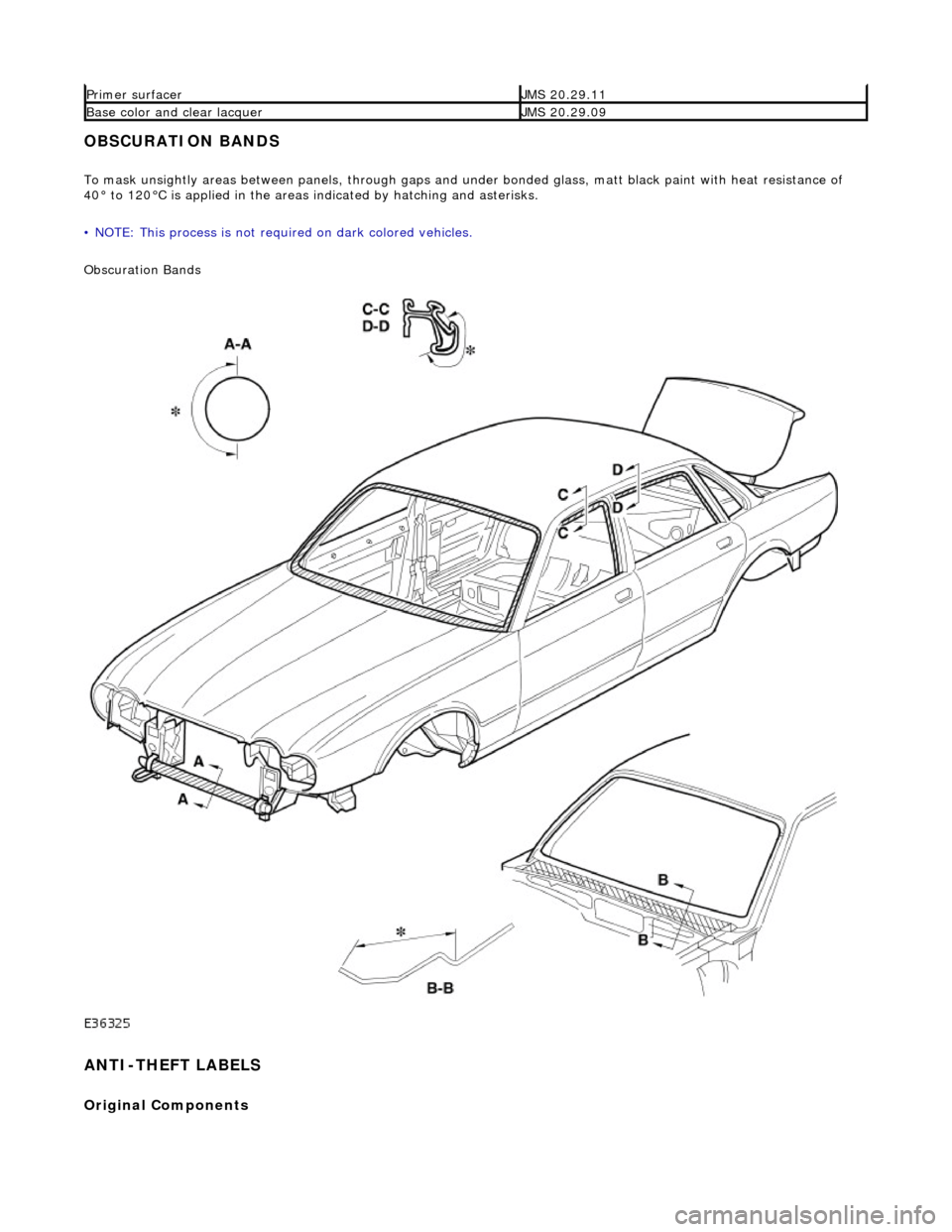
OBSCURATION BANDS
To mask unsightly areas between panels, through gaps and under bonded glass, matt black paint with heat resistance of
40° to 120°C is applied in the areas indicated by hatching and asterisks.
• NOTE: This process is not requ ired on dark colored vehicles.
Obscuration Bands
ANTI-THEFT LABELS
Original Components
Primer surfacerJMS 20.29.11
Base color and clear lacquerJMS 20.29.09
Page 2405 of 2490

On North American specification vehicles, the VIN is marked on all major external panels, certain structural members and
power / transmission units. The labels ca rrying this information are known as 'Label-Anti-theft VIN (USA body panel only)'
or 'Label-Anti-theft-Engine and Gearbo x (U.S.A. only),' drawing reference A .
Replacement Components
Only genuine Jaguar replacement parts must be used in the repair of a vehicle. Furthermore, any new parts replacing items
carrying a VIN label must have either 'Label-Anti-theft Replacement Part (USA body panel only)' or 'Label-Anti-theft
Replacement Part-Engine and Gearbox (U.S.A . only),' drawing reference B , fitted in a different location to the previous
label.
A protective mask used to prevent the replacement part la bel from being damaged or obscured during the refinishing /
protection processes, must be remo ved prior to customer hand-over.
Procurement
Anti-theft labels may only be ordered from Jaguar Cars through :
Product Compliance Dept.,
Jaguar Inc.,
555 MacArthur Blvd.,
Mahwah
NJ 07430
Label Fitting Process
CAUTION: It is a requirement of United States of America federal law th at the protective mask is removed from all
anti-theft labels after performing painting and rustproofing operations. Fail ure to comply with this requirement may render
both the manufacturer and the de aler in violation of the law.
• NOTE: Any attempt to remove an anti-t heft label will destroy that label. Ensure correct location before affixing.
Using a suitable solvent clean the area where the anti-theft label is to be affixed. Peel the backing from the label and
position on the panel. Carry out all refini shing / protection processes. Remove the anti-theft label protective mask prior to
vehicle handover to the customer.
Page 2406 of 2490

APPLICATION OF STONE CHIP PROTECTION
Apply approved material to the areas indicated by hatching.
REPAIR OF PAINTED COACHLINES
Panel Preparation
Existing painted coachlines can be removed using a suitable soft cloth moistened with thinners and/or acetone.
New coachlines must be applied over the lacquer coat, using two-pack 'solid' paints (ie non-metallic).
• NOTE: Lacquer must not be applied over the coachlines.
Where applicable, refinish the repaired panel (s), followin g Jaguar approved paint re-finishing procedures, including
application and drying of the two-pack lacquer coat.
Page 2407 of 2490

For coachline specifications, see page? .
Tape Application
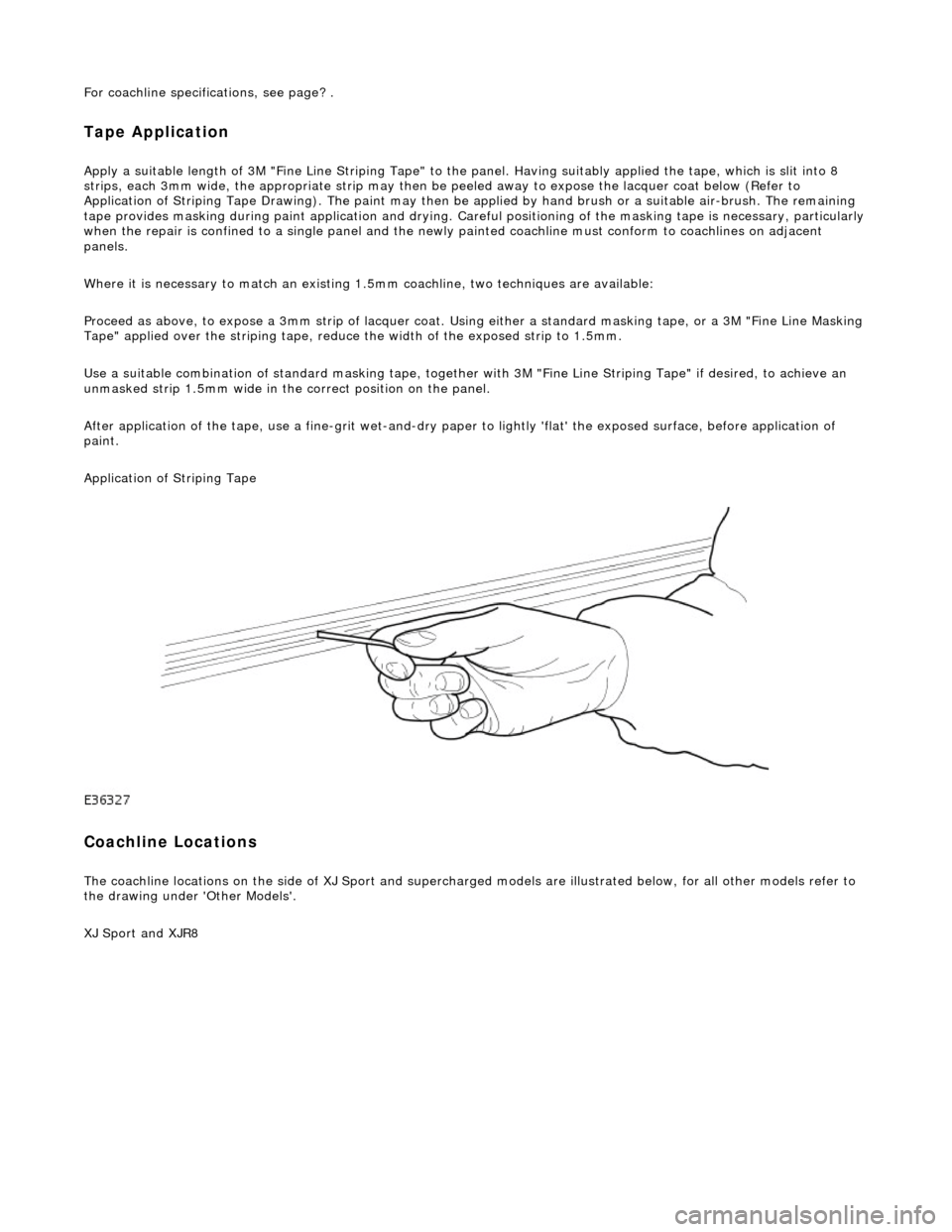
Apply a suitable length of 3M "Fine Line Striping Tape" to the panel. Having suitably applied the tape, which is slit into 8
strips, each 3mm wide, the appr opriate strip may then be peeled away to expose the lacquer coat below (Refer to
Application of Striping Tape Drawing). The paint may then be applied by hand brush or a suitable air-brush. The remaining
tape provides masking during paint applicat ion and drying. Careful positioning of the masking tape is necessary, particularly
when the repair is confined to a single panel and the newly painted coachline mu st conform to coachlines on adjacent
panels.
Where it is necessary to match an existing 1.5mm coachline, two tec hniques are available:
Proceed as above, to expose a 3mm strip of lacquer coat. Using either a standard masking tape, or a 3M "Fine Line Masking
Tape" applied over the striping tape, reduce the width of the exposed strip to 1.5mm.
Use a suitable combination of standard mask ing tape, together with 3M "Fine Line Striping Tape" if desired, to achieve an
unmasked strip 1.5mm wide in the correct position on the panel.
After application of the tape, use a fine-g rit wet-and-dry paper to lightly 'flat' the exposed surface, before application of
paint.
Application of Striping Tape
Coachline Locations
The coachline locations on the side of XJ Sport and supercharged models are illustrated below, for all other models refer to
the drawing under 'Other Models'.
XJ Sport and XJR8
Page 2412 of 2490

Prior to commencing any work, bumper damage should be assessed for repairability and categorized in accordance with the
following guidelines. Bumper covers that are torn or holed are not repairable and must be discarded.
CAUTION: Cosmetic appearance must no t jeopardise safety. No attempt must be made to repair bumper covers
damaged beyond category three. Damage of this extent will compromise the protective performance of the cover and it
must be renewed. The thermo-s etting nature of the cover material, preclude s the repair of splits by heat or welding
techniques.
Repair Materials
Repair of accepted damage for categories 2 and 3 may be carried out using 3M '5900 FPRM' (Flexible part repair material)
or Kent Industries 'Urepatch'. Repair product manufacturers' recommendations an d procedures must always be strictly
followed.
Bumper Cover Refinishing
The paint refinishing system must be approved by Jaguar Cars Ltd., and be appropriate for polyurethane substrate
application. It is essential that the fini shing clear lacquer includes a plasticising ingredient (mixed to the manufacturer's
recommendation) that will achieve the 'semi-fl ex' condition of the factory finished item.
Bumper Cover Support
Exposure to heat decreases bumper cover rigidity. Covers removed for repair mu st therefore be supported to prevent
distortion and sagging during the paint curing process. Where the original bumper cover has been repaired, the beam will
provide sufficient support for the centre section. It is recommended that the side armatu res are supported as they would be
on the vehicle. If a new cover is required, the beam may be temporarily fitted to provide the necessary support during
refinishing.
CAUTION: During heat cure, the effective panel temperature must not exceed 95°C.
Simple Jig Constr uction for Bumper Cover Support
CategoryDamage
CosmeticAbrasion to surface paint finish only
Substrate surfaceDeep scratches, gouges or lo calized radial stress cracks.
Substrate
penetrationSplits not exceeding 100mm. Splits radiating fr om a gouge and accompanied by localized stress
cracks.
Page 2416 of 2490

Replacement bumper cover assemblies includer side armatures, which should be removed from discarded bumper
assemblies and rout ed for recycling.
BODY SIDE MOULDINGS
Description
Two types of moulding are fitted to the standard wheelbase sedan. The lower mouldings are positioned on the body / door
lower feature lines. Where applicable, the upper mouldings are positioned using the lower mouldings as data. Replacement
lower mouldings are supplied in a primed condition and must be finished as detailed in this section.
Side Moulding Positions
Body Closures
Clearances and Alignments
When any panel, closure or body component is renewed, refitted or reset, the specified clearances and alignments must be
restored. This ensures that vehicle appearance and operation fully satisfy design intent and the customer.
Clearances
Gaps should be uniform around body panel contours and must be parallel to within 1mm in a 400mm linear measurement.
LocationFinishApplicationFixing method
UpperPolished stainless steelDaimler / VDPSelf adhesive
LowerBody colorAll modelsSelf adhesive
1Adhesive tape
2Moulding, Daimler/VDP
3Moulding all models
Page 2417 of 2490

Panels centered between two adjacent panels must have equal gaps on either side. For exceptions to this, refer to the
appropriate specification. Gaps between ad jacent panels or components must not expose harnesses, labels, brackets or
visually poor joint or assembly conditions.
• NOTE: Sliding roof panel clearances are specified without the edge seal installed.
Areas of particular concern are, fuel filler flap, trunk lid to fenders and saddle panels, hood to fenders, grill and headlamps,
sliding roof to main roof panel, door gaps at fenders, B\C posts, roof drip rail an d rocker panel, and bumper cover to fenders
and cross car assemblies
Alignment
Panels must be correctly profiled to maintain cosmetic appearance, and ensure co rrect seating of seals with minimal wind
noise. Areas of particular concern are hood to fenders, trunk lid to fenders and saddle panels, doors to apertures, doors to
fenders and adjacent doors and relationship of the sliding roof panel leading and trailing edges to the main roof panel.
Exterior Fitments
Bezels, trims and lamps must be concentric with apertu res and have equal clearances with adjacent panels.
Areas of particular concern are headlamp to hood, fender and trim panel, exhaust tailpipe trim to bumper cover cut-out,
rear lamp assembly to trunk lid, fender and bumper cover trim, and side feature lines including body side mouldings, fender
to door and door to door.
Exterior Clearances and Alignments-Front