Engine general JAGUAR X308 1998 2.G Owner's Manual
[x] Cancel search | Manufacturer: JAGUAR, Model Year: 1998, Model line: X308, Model: JAGUAR X308 1998 2.GPages: 2490, PDF Size: 69.81 MB
Page 633 of 2490

пЃ¬I
dentify the VCT oil supply gallery and the 8 mm blind rivet.
пЃ¬U
sing a suitable 3 mm punch release the centre of the blind rivet until
it is released from the outer part of the blind rivet.
пЃ¬U
sing a suitable extraction tool, remo
ve the remaining part of the blind
rivet.
2. Clean the component mating faces.
3.
Check cylinder head face for distortio
n, across the center and from corner
to corner.
4. For cylinder head face distortion data, refer to specifications.For additional
information, refer to: Specifications
(303
-00 Engine System - General
Information, Specifications).
5.
NOTE: For
cylinder head with
distortion above the
maximum allowance,
the cylinder head
material must be
measured.
Measure the
cylinder head
material.
пЃ¬Che
ck
measurement
from the
centre of the
exhaust
dowel to the
cylinder head
face as
shown.
пЃ¬If the
measurement
is less than
51.88 mm
the cylinder
head requires
replacement.
6.
Install a new gasket to the downpipe catalyst flange.
7. Install and align a new cylinder head gasket to the cylinder block face.
Page 641 of 2490
2.
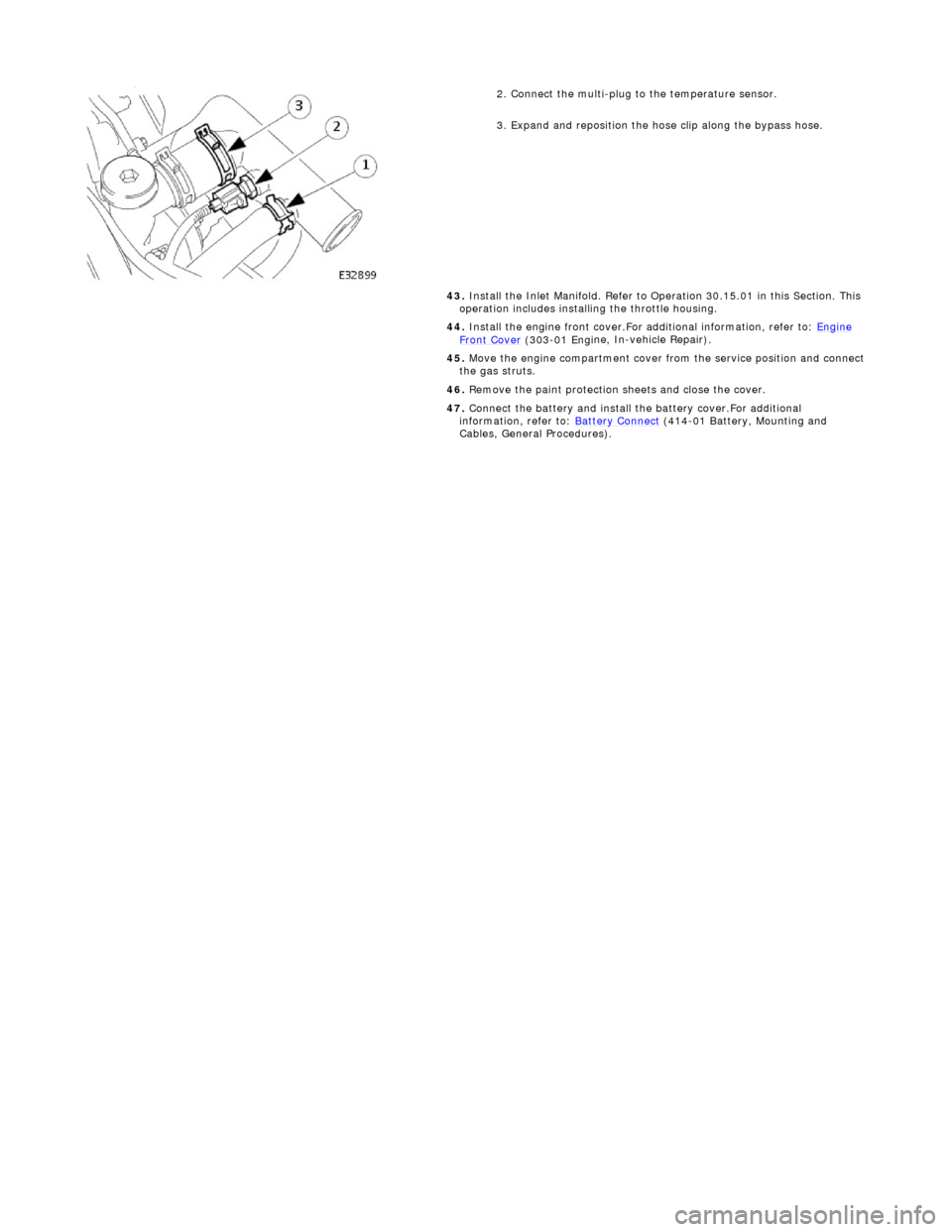
Connect the multi-plug to the temperature sensor.
3. Expand and reposition the hose clip along the bypass hose.
43. Install the Inlet Manifold. Refer to Operation 30.15.01 in this Section. This
operation includes installing the throttle housing.
44. Install the engine front cover.For additional information, refer to: Engine
Front Cover (303-01 Engi
ne, In-vehicle Repair).
45. Move the engine compartment cover from the service position and connect
the gas struts.
46. Remove the paint protection sheets and close the cover.
47. Connect the battery and install th e battery cover.For additional
information, refer to: Battery Connect
(414
-01 Battery, Mounting and
Cables, General Procedures).
Page 858 of 2490
23.
Install the supercharger driv e belt tensioner. Refer to
Operation 18.50.24.
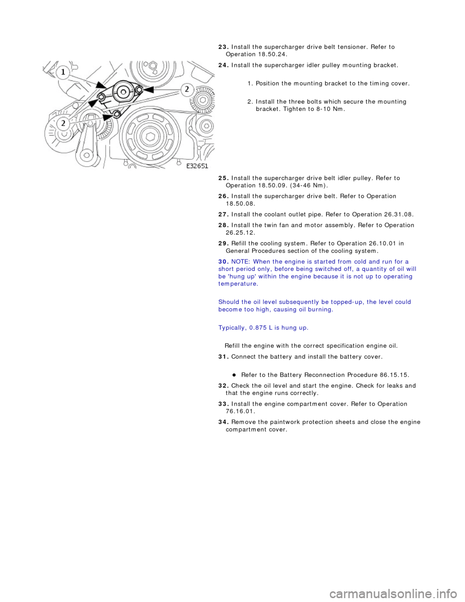
24. Install the supercharger idle r pulley mounting bracket.
1. Position the mounting bracket to the timing cover.
2. Install the three bolts which secure the mounting bracket. Tighten to 8-10 Nm.
25. Install the supercharger drive belt idler pulley. Refer to
Operation 18.50.09. (34-46 Nm).
26. Install the supercharger driv e belt. Refer to Operation
18.50.08.
27. Install the coolant outlet pipe. Refer to Operation 26.31.08.
28. Install the twin fan and motor assembly. Refer to Operation
26.25.12.
29. Refill the cooling system. Refer to Operation 26.10.01 in
General Procedures section of the cooling system.
30. NOTE: When the engine is star ted from cold and run for a
short period only, before being swit ched off, a quantity of oil will
be 'hung up' within the engine because it is not up to operating
temperature.
Should the oil level subsequently be topped-up, the level could
become too high, causing oil burning.
Typically, 0.875 L is hung up.
Refill the engine with the correct specification engine oil.
31. Connect the battery and in stall the battery cover.
пЃ¬Refer to the Battery Reconnection Procedure 86.15.15.
32. Check the oil level and start th e engine. Check for leaks and
that the engine runs correctly.
33. Install the engine compartmen t cover. Refer to Operation
76.16.01.
34. Remove the paintwork protection sheets and close the engine
compartment cover.
Page 923 of 2490
be 'hun
g up' within the engine because it is not up to operating
temperature.
Should the oil level subsequently be topped-up, the level could
become too high, causing oil burning.
Typically, 0.875L is hung up.
Refill the engine with the correct specification engine oil.
58. Refill the automatic transmission. Refer to Section 307-01A,
Operation 44.24. 02.
59. Refill and bleed the power stee ring system. Refer to Section
211-02 General Procedures.
60. Repressurise the air conditioni ng system. Refer to Operation
82.30.30 and note all Wa rnings and Cautions.
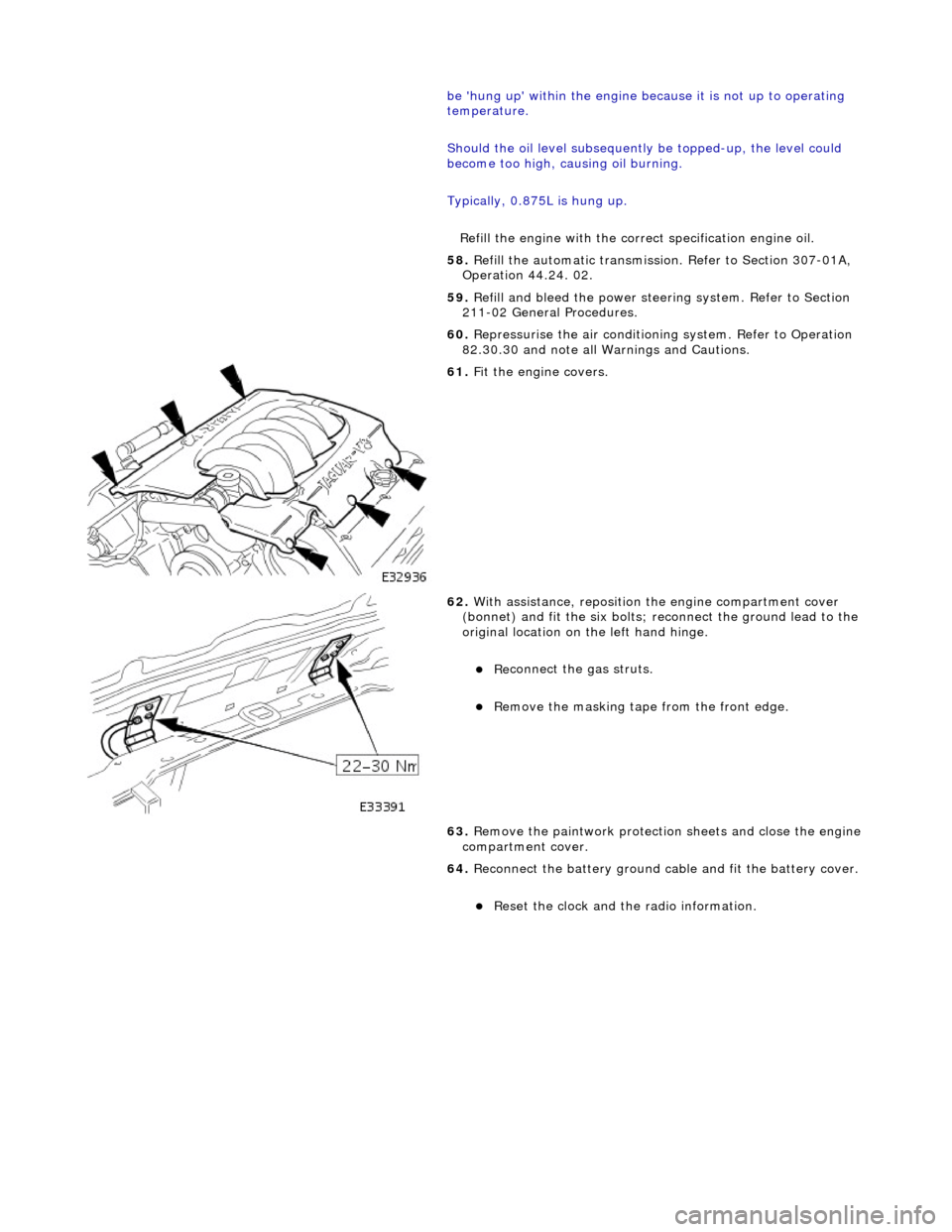
61
.
Fit the engine covers.
62
.
With assistance, reposition the engine compartment cover
(bonnet) and fit the si x bolts; reconnect the ground lead to the
original location on the left hand hinge.
пЃ¬Re
connect the gas struts.
пЃ¬R
emove the masking tape from the front edge.
63. Remove the paintwork protection sheets and close the engine
compartment cover.
64. Reconnect the battery ground cable and fit the battery cover.
пЃ¬Re
set the clock and the radio information.
Page 965 of 2490

Engine Cooling - Coolant Outlet Pipe
Re
moval and Installation
Remov
al
Installation
1.
O
pen the engine compartment and fit paintwork protection
sheets.
2. Drain the radiator. Refer to Ge neral Procedures. Retain the
coolant drain tray in position to catch any spillage when
removing the outlet pipe.
3. Di
sconnect the hoses and multi-plug from the coolant outlet
pipe.
1. Release and reposition th e hose clip, and disconnect
the top hose.
2. Release and reposition th e hose clip, and disconnect
the heater hose.
3. Disconnect the multi-plug from the temperature sensor and unscrew the sens or from the outlet pipe.
4. Release and reposition the hose clip along the bypass
hose.
4. R
emove the coolant outlet pipe.
1. Remove the four bolts which secure the outlet pipe.
2. Remove the outlet pipe from the bypass hose and
from the cylinder heads.
5. Remove and discard the sealing rings from the outlet pipe
grooves.
1. Installation is the reverse of the remova l procedure. Use new
sealing rings on the coolant outlet pipe.
2. Tighten the coolant outlet pipe bolts to 10-14 Nm If replacing
the coolant temperature sensor, tighten to 15-19 Nm.
3. Refill the cooling system as de scribed in General Procedures.
Page 979 of 2490
16
.
Refill the cooling system. Refer to the Refill procedure in
General Procedures.
17. Repressurise the climate cont rol system. Refer to Section
412-03 Observe all safety warnin gs and precautions stated in
that section.
18. Close the engine compartment cover.
19. Connect the battery and fit the battery cover. Reset the clock
and the radio.
Page 986 of 2490
16
. Re
fill the cooling system. Refer to the Refill procedure in
General Procedures.
17. Repressurise the climate cont rol system. Refer to Section
412-03 Observe all safety warnin gs and precautions stated in
that section.
18. Close the engine compartment cover.
19. Connect the battery and fit the battery cover. Reset the clock
and the radio.
Page 987 of 2490

Engine Cooling - Radiator Lo
wer Hose4.0L NA V8
- AJ27/3.2L NA V8 -
AJ26
Re
moval and Installation
Remov
al
Installation
1.
O
pen the engine compartment and fit paintwork protection
sheets.
2. Drain the radiator. Refer to Ge neral Procedures. Retain the
coolant drain tray in position to catch any spillage when
removing the thermostat cover.
3. Di
sconnect the radiator bott
om hose from the thermostat
cover.
1. Release and reposition th e hose clip, and disconnect
the bottom hose.
4. D
isconnect the bottom hose from the radiator.
1. Slacken the hose retaining clip and reposition the clip
along the hose.
2. Disconnect the hose from the radiator.
5. Remove the spring band clips from the hose.
1. Installation is th e reverse of the re moval procedure.
2. Refill the cooling system as de scribed in General Procedures.
Page 990 of 2490

Engine Cooling - Radiator Upper Hose4.0L NA V8 - AJ27/3.2L NA V8 -
AJ26
Re mo
val and Installation
Remova
l
Installation
1.
Op
en the engine compartment and fit paintwork protection
sheets.
2. Drain the radiator. Refer to Ge neral Procedures. Retain the
coolant drain tray in position to catch any spillage when
removing the hose.
3. Disc
onnect the top hose from the coolant outlet pipe.
1. Release and reposition th e hose clip, and disconnect
the top hose.
4. R
e
lease the top hose from the radiator.
1. Release the hose retaining clip and reposition the clip along the hose.
2. Disconnect the hose from the radiator.
пЃ¬Re move t
he hose clips from the top hose.
1. Installation is th e reverse of the re moval procedure.
2. Refill the cooling system as de scribed in General Procedures.
Page 991 of 2490

Engine Cooling - Radiator Upper Hose4.0L SC V8 - AJ26
Re
moval and Installation
Remov
al
Installation
1.
O
pen the engine compartment and fit paintwork protection
sheets.
2. Drain the radiator. Refer to Ge neral Procedures. Retain the
coolant drain tray in position to catch any spillage when
removing the hose.
3. Di
sconnect the top hose from the coolant outlet pipe.
1. Release and reposition th e hose clip, and disconnect
the top hose.
4. R
elease the top hose from the radiator.
1. Release the hose retaining clip and reposition the clip along the hose.
2. Disconnect the hose from the radiator.
пЃ¬Re
move the hose clips from the top hose.
1. Installation is th e reverse of the re moval procedure.
2. Refill the cooling system as de scribed in General Procedures.