Engine general JAGUAR X308 1998 2.G Repair Manual
[x] Cancel search | Manufacturer: JAGUAR, Model Year: 1998, Model line: X308, Model: JAGUAR X308 1998 2.GPages: 2490, PDF Size: 69.81 MB
Page 1546 of 2490
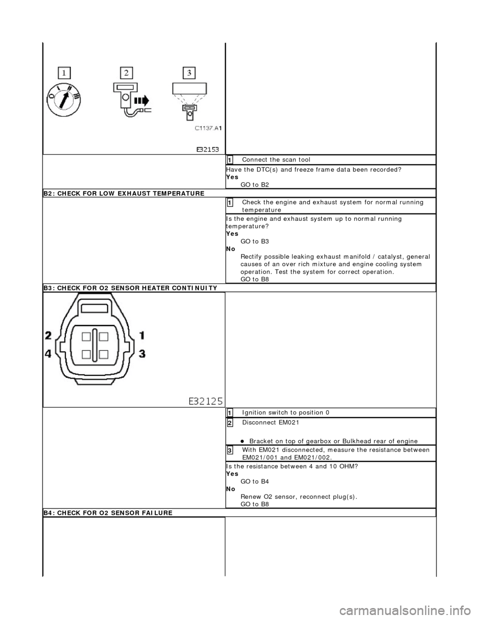
Connect the scan tool 1
Have the DTC(s) and freeze frame data been recorded?
Yes GO to B2
B2: CHECK FOR LOW EX HAUST TEMPERATURE
Check the engine and exhaust system for normal running
temperature 1
Is the engine and exhaust sy stem up to normal running
temperature?
Yes GO to B3
No Rectify possible leaking exhaust manifold / catalyst, general
causes of an over rich mixture and engine cooling system
operation. Test the system for correct operation.
GO to B8
B3: CHECK FOR O2 SENS OR HEATER CONTINUITY
Ignition switch to position 0 1
Disconnect EM021
пЃ¬Bracket on top of gearbox or Bulkhead rear of engine
2
With EM021 disconnected, measure the resistance between
EM021/001 and EM021/002. 3
Is the resistance between 4 and 10 OHM?
Yes
GO to B4
No Renew O2 sensor, reconnect plug(s).
GO to B8
B4: CHECK FOR O2 SENSOR FAILURE
Page 1570 of 2490
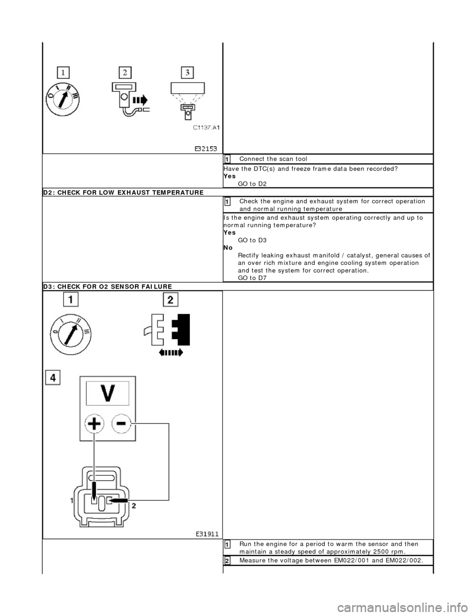
Connect the scan tool 1
Have the DTC(s) and freeze frame data been recorded?
Yes GO to D2
D2: CHECK FOR LOW EXHAUST TEMPERATURE
Check the engine and exhaust system for correct operation
and normal running temperature 1
Is the engine and exhaust system operating correctly and up to
normal running temperature?
Yes GO to D3
No Rectify leaking exhaust manifold / catalyst, general causes of
an over rich mixture and engine cooling system operation
and test the system for correct operation.
GO to D7
D3: CHECK FOR O2 SENSOR FAILURE
Run the engine for a period to warm the sensor and then
maintain a steady speed of approximately 2500 rpm. 1
Measure the voltage between EM022/001 and EM022/002. 2
Page 1598 of 2490
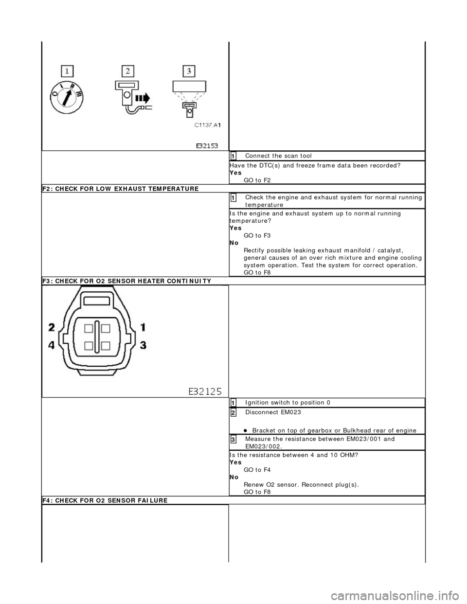
Connect the scan tool 1
Have the DTC(s) and freeze frame data been recorded?
Yes GO to F2
F2: CHECK FOR LOW EXHAUST TEMPERATURE
Check the engine and exhaust system for normal running
temperature 1
Is the engine and exhaust sy stem up to normal running
temperature?
Yes GO to F3
No Rectify possible leaking exhaust manifold / catalyst,
general causes of an over ri ch mixture and engine cooling
system operation. Test the sy stem for correct operation.
GO to F8
F3: CHECK FOR O2 SENSOR HEATER CONTINUITY
Ignition switch to position 0 1
Disconnect EM023
пЃ¬Bracket on top of gearbox or Bulkhead rear of engine
2
Measure the resistance between EM023/001 and
EM023/002. 3
Is the resistance between 4 and 10 OHM?
Yes
GO to F4
No Renew O2 sensor. Reconnect plug(s).
GO to F8
F4: CHECK FOR O2 SENSOR FAILURE
Page 1625 of 2490
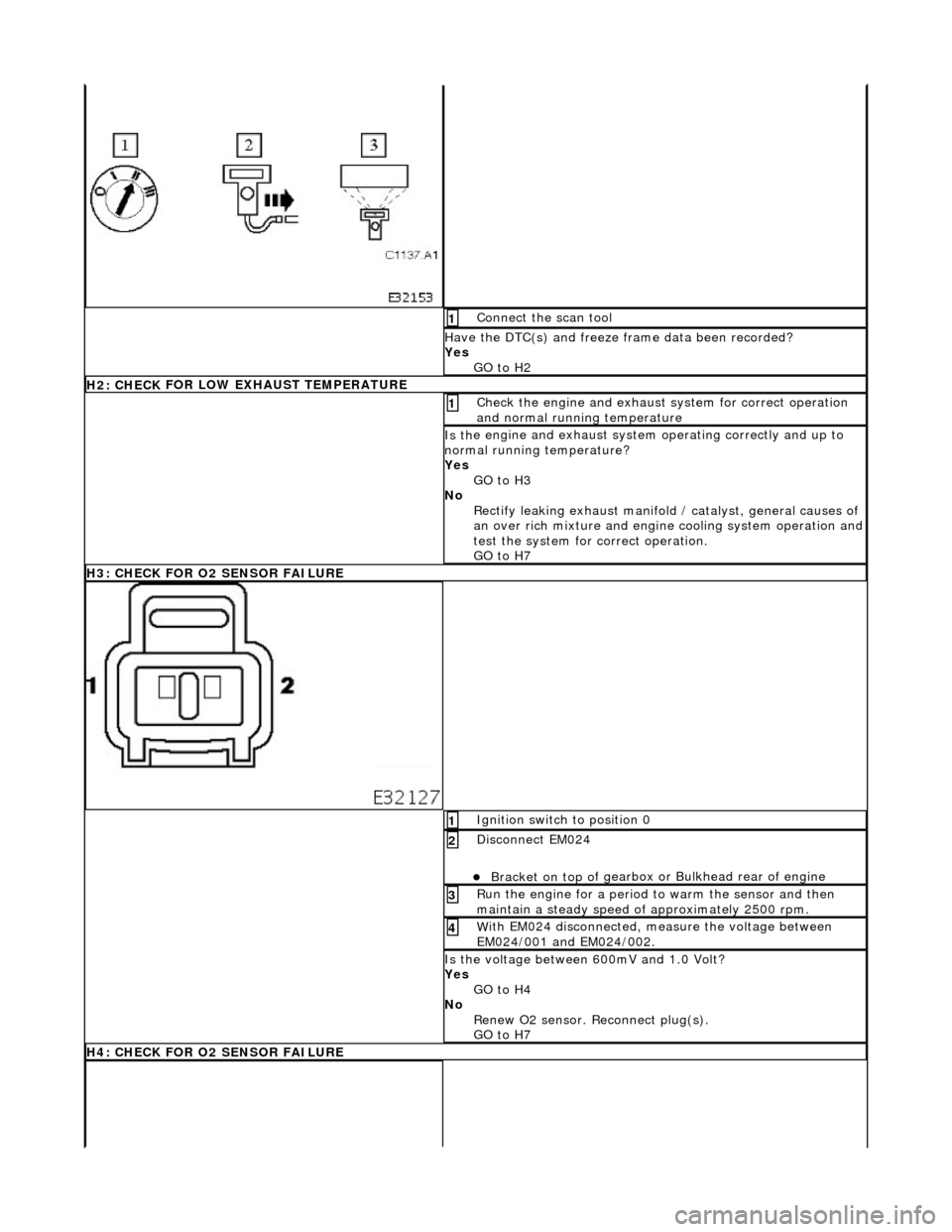
Conne
ct the scan tool
1
Have the DTC(s) and fr
eeze
frame data been recorded?
Yes GO to H2
H2: CHECK
FOR LOW EXHAUST TEMPERATURE
Chec
k the engine and exhaust
system for correct operation
and normal running temperature
1
Is th
e engine and exhaust system operating correctly and up to
normal running temperature?
Yes GO to H3
No Rectify leaking exhaust manifold / catalyst, general causes of
an over rich mixture and engine cooling system operation and
test the system for correct operation.
GO to H7
H
3: CHECK FOR O2 SENSOR FAILURE
I
gnition switch to position 0
1
Di
sconnect EM024
пЃ¬Bracket on top o
f gearbox or
Bulkhead rear of engine
2
R
un the engine for a period to
warm the sensor and then
maintain a steady speed of approximately 2500 rpm.
3
W
ith EM024 disconnected, measure the voltage between
EM024/001 and EM024/002.
4
Is
the voltage between 600mV and 1.0 Volt?
Yes GO to H4
No Renew O2 sensor. Reconnect plug(s).
GO to H7
H
4: CHECK FOR O2 SENSOR FAILURE
Page 1688 of 2490
Fuel System - General Inform
ation - Fuel System
Description an
d Operation
The fuel tank is mounted across the vehicle behind the passenger compartment bulkhead.
Fuel is drawn by the fuel pump from the tank and then supplied to the two fuel rails, via a filter.
Fuel injectors are installed in the fuel ra ils on each side of the intake manifold.
The amount of fuel injected into th e engine is controlled by the ECM.
A cross-over pipe connects the two fuel ra ils together at the front of the manifold.
A test valve in the cross-over pipe allo ws the fuel rail to be pressurized and de-pressurized during the servicing and
troubleshooting procedures.
A pressure regulator on the rear of the right fuel rail controls the pressure in the fuel rails.
A return line directs excess fuel from the pressure regulator back to the fuel tank.
Operation and service procedures
The fuel injector
s, rails, pres
sure regulator and, wher e fitted, supercharger are described in greater detail in Section 303-04
together with servicing procedures.
The fuel tank, pump, fuel level senders and fuel lines are similarly covered in Section 310-01.
Page 1689 of 2490
Fuel System - General Information - Fuel System Pre
ssure Check
Gen
eral Procedures
WARNING: Working on the fuel system re sults in fuel and fuel vapor being present in the atmosphere. Fuel vapor is
extremely flammable, hence great care must be taken whilst working on the fuel system. Adhere strictly to the following
precautions:
пЃ¬D
o not smoke in the work area
пЃ¬Di
splay
NO SMOKING signs around the work area
пЃ¬D
isconnect the battery before
working on the fuel system
пЃ¬Av
oid sparks
пЃ¬Make sure sui
table fire ex
tinguishers are at hand
пЃ¬Make sure absor
bent material is at
hand to soak up any spillage
пЃ¬Make sure the work area is
well ventilated
пЃ¬M
ake sure that the gauge is correctly conn
ected, and that all connections are secure BEFORE starting the engine
пЃ¬DO N
OT
disconnect the gauge from the schrader valve while the engine is running
пЃ¬Make su
re the schrader valve reseals once the gauge is disconnected
• NOTE: Depending on the design of the ga uge set, there may be a drain valve and tube. Make sure this valve is closed, and
the drain tube placed in a suitable container BEFORE connecting the gauge to the schrader valve.
1. Make sure the vehi
cle is in
Park for vehicles with automatic
transmission, Neutral for vehicles with manual transmission.
2. Apply the parking brake.
3. Place suitable absorbent material around the schrader valve to
absorb any spillage when connecting the gauge set.
4. Remove the protective cap from the schrader valve.
5. Connect the gauge, using adaptors if required.
6. Remove the absorbent material and dispose of safely.
7. Disconnect and plug the vacuum hose from the pressure
regulator.
8. Start the engine and record the fuel pressure reading.
пЃ¬As a gui
de, the fuel pressu
re should be approximately 3.0
bar (44.1 psi) with the regulator disconnected.
9. With the engine still running, reconnect the vacuum hose to
the pressure regulator an d record the reading.
пЃ¬Th
e pressure should dr
op to approximately 2.6 bar (38
psi) when the vacuum hose is reconnected.
10. Switch off the engine.
11. Place more absorbent material around the schrader valve.
12. Where fitted, open the drain valve and allow the fuel from the
gauge and line to flow into the container to depressurize the
system.
13. Disconnect and remove the gauge set and any adaptors.
14. Clean up any fuel which may have been spilt and remove the
absorbent material. Dispose of safely.
15. Refit and secure the protective cap to the schrader valve.
16. Reconnect the fuel pressure regulator vacuum hose.
17. Start the engine and make sure there are no leaks.
Page 1690 of 2490
Fuel System - General Information - Fuel System Pressure Rele
ase
Gen
e
ral Procedures
S p
ecial Tool(s)
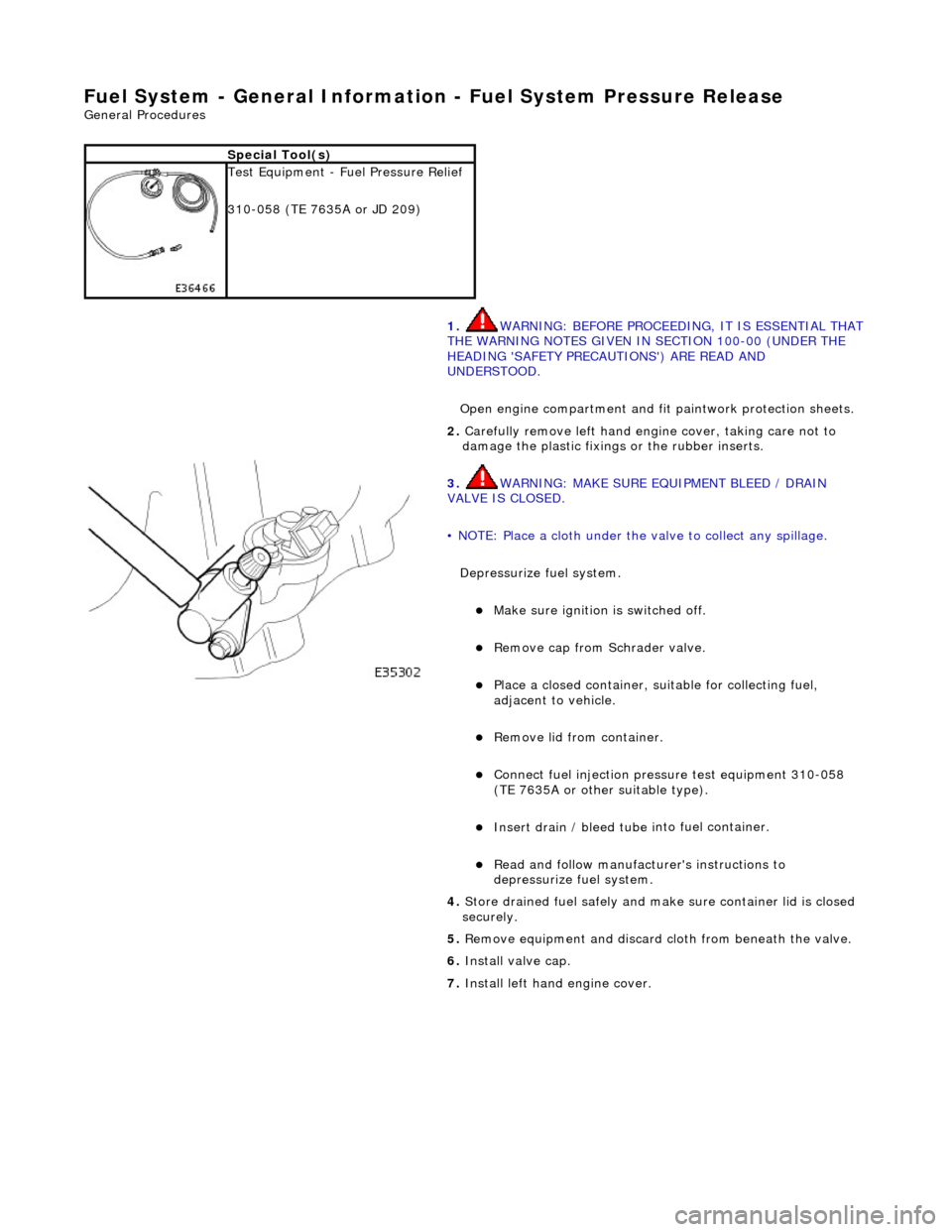
Tes
t
Equipment - Fuel Pressure Relief
310-058 (TE 7635A or JD 209)
1. WARNING: BEFORE PROCEEDING, IT IS ESSENTIAL THAT
THE WARNING NOTES GIVEN IN SECTION 100-00 (UNDER THE
HEADING 'SAFETY PRECAUTIONS') ARE READ AND
UNDERSTOOD.
Open engine compartment and fi t paintwork protection sheets.
2. Carefull
y remove left
hand engine cover, taking care not to
damage the plasti c fixings or the rubber inserts.
3. WA
RNING: MAKE SURE EQUIPMENT BLEED / DRAIN
VALVE IS CLOSED.
• NOTE: Place a cloth under the valve to collect any spillage.
Depressurize fuel system.
пЃ¬Make sure ignition i s
switched off.
пЃ¬R
e
move cap from Schrader valve.
пЃ¬Pla
c
e a closed container, su
itable for collecting fuel,
adjacent to vehicle.
пЃ¬R e
move lid from container.
пЃ¬Conne
ct
fuel injection pressu
re test equipment 310-058
(TE 7635A or other suitable type).
пЃ¬Insert drain / bleed tu be i
nto fuel container.
пЃ¬R
e
ad and follow manufacturer's instructions to
depressurize fuel system.
4. Store drained f u
el safely and make
sure container lid is closed
securely.
5. Remove equipment and discard cloth from beneath the valve.
6. Install valve cap.
7. Install left hand engine cover.
Page 1758 of 2490
Climate Control System - General Informatio
n - Climate Control System
D
iagn
osis and Testing
I
n
troduction
It is very i
m
portant to positive
ly identify the area of concern before starting a rectification procedure. A little time spent with
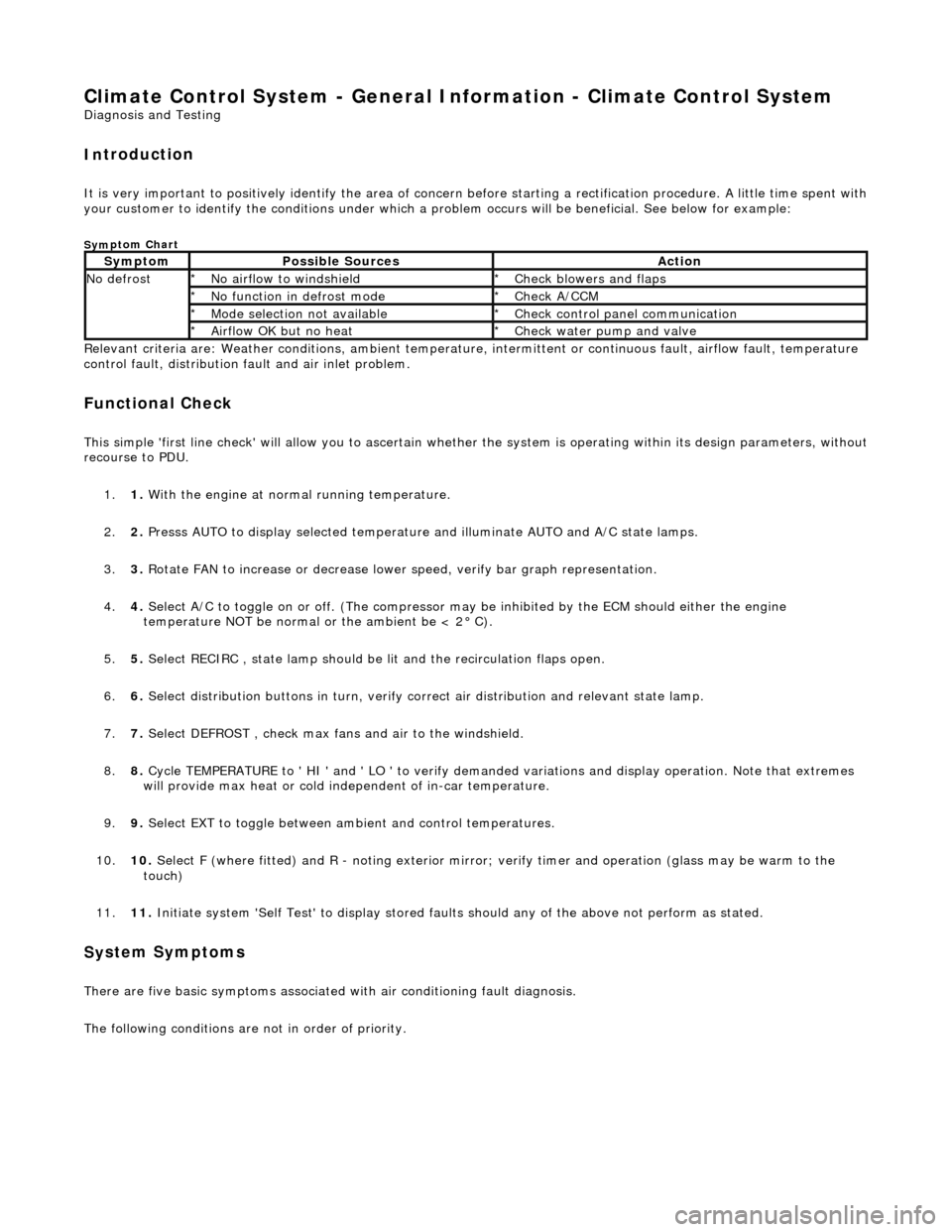
your customer to identify the conditions under which a pr oblem occurs will be beneficial. See below for example:
Sym
ptom Chart
Re
lev
ant criteria are: Weather conditions,
ambient temperature, intermittent or cont inuous fault, airflow fault, temperature
control fault, distribution fault and air inlet problem.
Functio n
al Check
This
s
imple 'first line check' will allo
w you to ascertain whether the system is operating within its design parameters, withou t
recourse to PDU.
1. 1. With the engine at normal running temperature.
2. 2. Presss AUTO to display selected temperature and illuminate AUTO and A/C state lamps.
3. 3. Rotate FAN to increase or decrease lowe r speed, verify bar graph representation.
4. 4. Select A/C to toggle on or off. (T he compressor may be inhibited by the ECM should either the engine
temperature NOT be normal or the ambient be < 2В° C).
5. 5. Select RECIRC , state lamp should be lit and the recirculation flaps open.
6. 6. Select distribution butt ons in turn, verify correct air distribution and relevant state lamp.
7. 7. Select DEFROST , check max fans and air to the windshield.
8. 8. Cycle TEMPERATURE to ' HI ' and ' LO ' to verify demanded variations and display operation. Note that extremes
will provide max heat or cold independent of in-car temperature.
9. 9. Select EXT to toggle between am bient and control temperatures.
10. 10. Select F (where fitted) and R - noting exterior mirror; verify timer and operation (glass may be warm to the
touch)
11. 11. Initiate system 'Self Test' to display stored faul ts should any of the above not perform as stated.
Sy
stem Symptoms
There
are five
basic symptoms associated
with air conditioning fault diagnosis.
The following conditions are not in order of priority.
Sy m
ptom
Possib
l
e Sources
Acti
o
n
N
o defrostN o
airflow to windshield
*
Check blower s and flaps
*
N o functi
on in defrost mode
*
Check A/CCM
*
Mo de s
election not available
*
Chec k
control panel communication
*
Ai rfl
ow OK but no heat
*
Check water pu
mp and valve
*
Page 1761 of 2490
Climate Co
ntrol System - General In
formation - Air Conditioning (A/C)
System Check - Re tail Procedure
Gen
eral Procedures
E
vacuating the Manifold Gauge Set
Connecting the Manifold Gauge Set
C
AUTION: Only use hoses with connectors wh
ich are dedicated to HFC 134A charge ports.
Stabilizing the System
1.
At
tach the center (service) hose to a vacuum pump and start
the pump. Open fully both high and low valves and allow the
vacuum to remove air and mois ture from the manifold set for
at least five minutes.
CAUTION: It is imperative th at the vacuum pump is not
subjected to a positi ve pressure of any degree. Therefore the
pump must be fitted wi th an isolation valve at the center (service
hose) connection and this valve mu st be closed before the pump
is switched off. This operation replaces the 'purge' procedure used
on previous systems. Observe the manufacturer's
recommendation with regard to vacuum pump oil changes.
Turn the vacuum pump off and isol ate it from the center service
hose but do not open the hose to atmosphere.
1. Att
achment of the hose quick release connectors to the high
and low side system ports is stra ightforward, provided that the
high and low valves are closed and the system is NOT
operational.
WARNING: UNDER NO CIRCUMSTANCES SHOULD THE
CONNECTIONS BE MADE WITH THE SYSTEM IN OPERATION OR
THE VALVES OPEN. SHOULD THE VALVES BE OPEN AND A
VACUUM PUMP OR REFRIGERANT CONTAINER ATTACHED, AN
EXPLOSION COULD OCCUR AS A RESULT OF HIGH PRESSURE
REFRIGERANT BEING FORCED BACK INTO THE VACUUM PUMP OR
CONTAINER.
Assessment of system operating efficiency and fault
classification may be achieved by using the facilities on your
Recovery / Recharging / Recycling station, follow the
manufacturer's instructions implicitly and observe all safety
considerations.
1. Accurate test gauge data wi
ll on
ly be attained if the system
temperatures and pressures are stabilized.
пЃ¬E
nsure that equipment and hoses cannot come into
contact with engine moving parts or sources of heat.
пЃ¬It is recommended th at a free standing air
mover is placed
in front of the vehicle to provide air flow through the
condenser / cooling system.
пЃ¬St
art the engine, allow it to attain normal working
temperature and set at fast idle (typically 1200 to 1500
rpm).
пЃ¬Select full
air condit
ioning performance.
пЃ¬With
all temperatures and pres
sures stable, or displaying
symptoms of faults; begin relevant test procedures.
Page 1762 of 2490
Climate Control System - General Infor
mation - Air Conditioning (A/C)
System Recovery, Evacuation and Charging
Gen e
ral Procedures
Recover / Reclaim
Ev
acuation
Charging
1.
CAUTIO
N: Read the procedures and instructions supplied
by the manufacturer of the air co nditioning service center before
commencing any process requiring the handling of refrigerant. In
addition to the manufacturer's in formation, observe all safety
precautions and advice deta iled in this section.
Disconnect battery ground lead; refer to 86.15.19.
2. Remove passenger side fi
rewall cover.
3. Remove driver side firewall cover.
4. Remove engine compar tment rear cover.
5. Re
move vehicle charge port
protective caps and connect
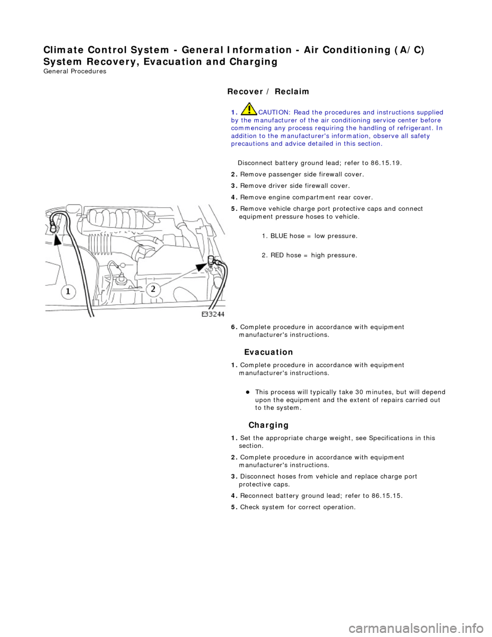
equipment pressure hoses to vehicle.
1. BLUE hose = low pressure.
2. RED hose = high pressure.
6. Complete procedure in ac cordance with equipment
manufacturer's instructions.
1. Complete procedure in ac cordance with equipment
manufacturer's instructions.
пЃ¬This proc
ess will typically ta
ke 30 minutes, but will depend
upon the equipment and the ex tent of repairs carried out
to the system.
1. Set the appropriate charge weight, see Specifications in this
section.
2. Complete procedure in ac cordance with equipment
manufacturer's instructions.
3. Disconnect hoses from vehicle and replace charge port
protective caps.
4. Reconnect battery ground lead; refer to 86.15.15.
5. Check system for correct operation.