Windshield JAGUAR X308 1998 2.G Owner's Manual
[x] Cancel search | Manufacturer: JAGUAR, Model Year: 1998, Model line: X308, Model: JAGUAR X308 1998 2.GPages: 2490, PDF Size: 69.81 MB
Page 2179 of 2490
Glass, Frames and Mechanisms - Glass, Frames and Mechanisms
Description and Operation
Fixed Glass
The 5 mm thick laminated and tinted glas s windshield is supplied with a moulded rubber seal and stainless trim.The inner
face of the glass adjacent to the seal is directly bonded to the windshield aperture flange, to form a stressed member of the
bodyshell. The 4 mm thick toughened and tinted glass backlight which is similarly bonded to the BIW, incorporates a
heating element and a mounting for the high level stop lamp. The 5 mm tempered and tinted glass quarter light which is
supplied as a complete assembly with stainless trim and seals, is directly bonded to the BIW aperture flanges.
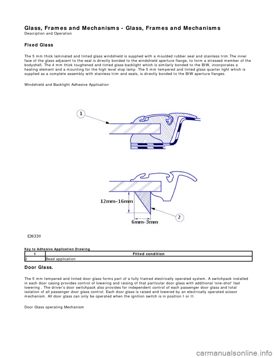
Windshield and Backlight Adhesive Application
Key to Adhesive Application Drawing
Door Glass.
The 5 mm tempered and tinted door glass forms part of a fully framed electrically operated system. A switchpack installed
in each door casing provides control of lowering and raising of that particular d oor glass with additional 'one-shot' fast
lowering . The driver's door switchpack also provides for independent control of each passenger door glass and total
isolation of all passenger door glass control. Each door glas s is raised and lowered by an electrically operated scissor
mechanism. All door glass can only be operated wh en the ignition switch is in position I or II.
Door Glass operating Mechanism
1Fitted condition
2Bead application
Page 2201 of 2490
Installation
the spray bottle with water and mix.
5. Apply cutting lubricant to the rear quarter window glass
adhesive.
6. Install the cutting tool blade BTB-WK4ZS to the cutting tool
BTB-WK10HD.
7. WARNING: When removing the rear quarter window
glass, personal protec tion must be worn. Failure to follow this
instruction may result in personal injury.
• NOTE: Apply cutting lubricant to the cutting tool frequently
through out the cutting process.
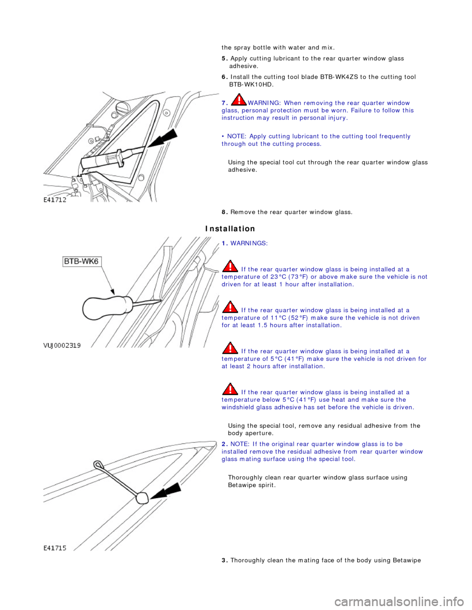
Using the special tool cut throug h the rear quarter window glass
adhesive.
8. Remove the rear quarter window glass.
1. WARNINGS:
If the rear quarter window glass is being installed at a
temperature of 23°C (73°F) or abov e make sure the vehicle is not
driven for at least 1 hour after installation.
If the rear quarter window glass is being installed at a
temperature of 11°C (52°F) make sure the vehicle is not driven
for at least 1.5 hours after installation.
If the rear quarter window glass is being installed at a
temperature of 5°C (41°F) make su re the vehicle is not driven for
at least 2 hours after installation.
If the rear quarter window glass is being installed at a
temperature below 5°C (41°F) use heat and make sure the
windshield glass adhesive has set before the vehicle is driven.
Using the special tool, remove any residual adhe sive from the
body aperture.
2. NOTE: If the original rear qu arter window glass is to be
installed remove the residual ad hesive from rear quarter window
glass mating surface using the special tool.
Thoroughly clean rear quarte r window glass surface using
Betawipe spirit.
3. Thoroughly clean the mating face of the body using Betawipe
Page 2207 of 2490

12. Pass free end of cheese wire through penetration and install
second cutting handle.
13. WARNING: When removing the rear window glass,
personal protection must be worn. Failure to follow this
instruction may result in personal injury.
• CAUTIONS:
Make sure the ch eese wire cannot contact the paintwork
while the the rear window glass ad hesive is being cut. Failure to
follow this instruction may result in damage to the vehicle.
When cutting, do not allow ch eese wire to contact edge of
window glass as this will crack the window glass.
• NOTE: Apply cutting lubricant to the cheese wire frequently
through out the cutting process.
With assistance and exercising care to avoid damaging the
paintwork, cut around the re ar window glass commencing
upwards and along the top.
14. Install the lifting handles to the windshield glass, and with
assistance carefully remove th e rear window glass from the
vehicle.
Page 2212 of 2490
Glass, Frames and Mechanisms - Windshield Glass
Removal and Installation
Removal
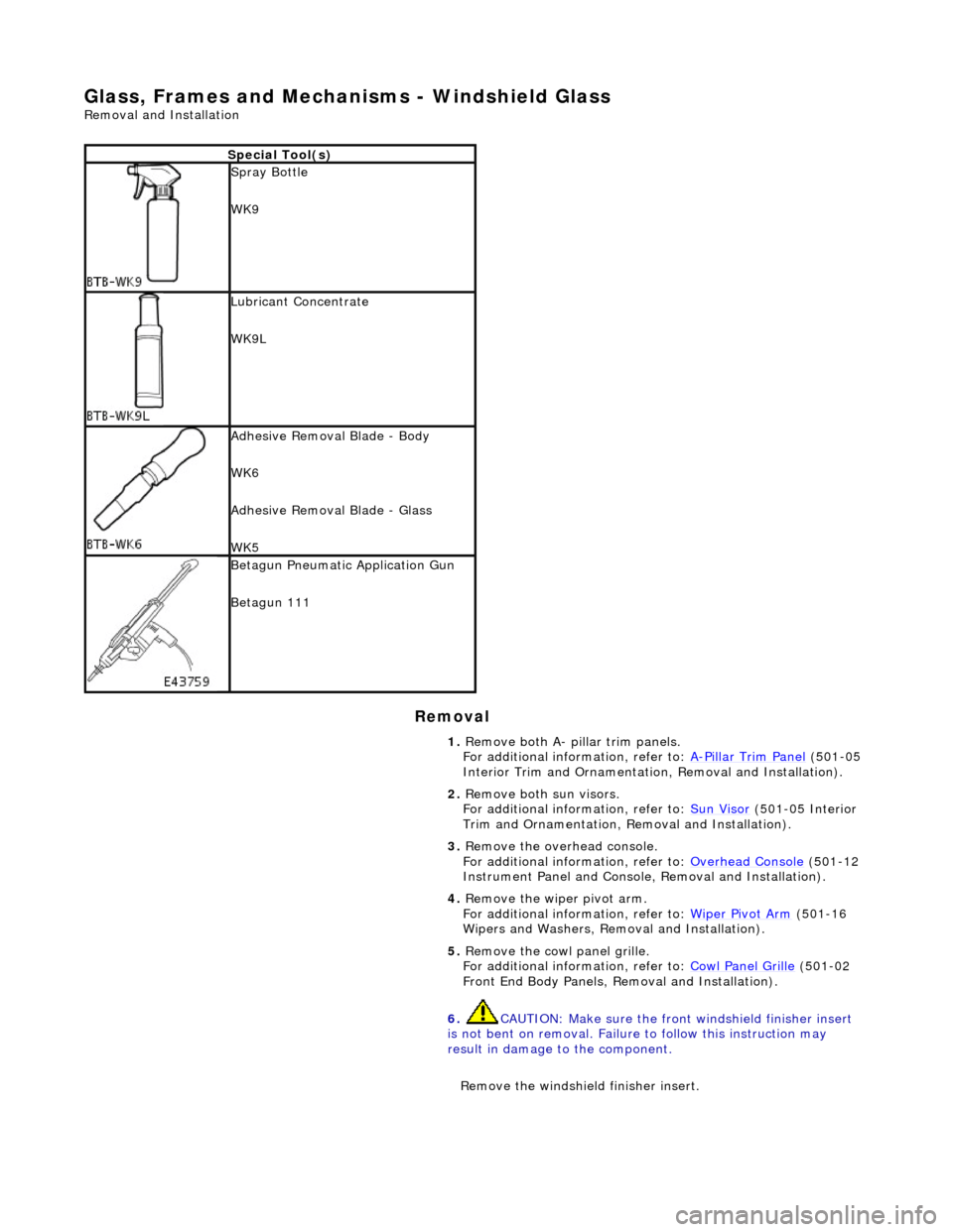
Special Tool(s)
Spray Bottle
WK9
Lubricant Concentrate
WK9L
Adhesive Removal Blade - Body
WK6
Adhesive Removal Blade - Glass
WK5
Betagun Pneumatic Application Gun
Betagun 111
1. Remove both A- pill ar trim panels.
For additional information, refer to: A
-Pillar Trim Panel (501-05
Interior Trim and Ornamentatio n, Removal and Installation).
2. Remove both sun visors.
For additional information, refer to: Sun Visor
(501-05 Interior
Trim and Ornamentation, Re moval and Installation).
3. Remove the overhead console.
For additional information, refer to: Overhead Console
(501-12
Instrument Panel and Console, Removal and Installation).
4. Remove the wiper pivot arm.
For additional information, refer to: Wiper Pivot Arm
(501-16
Wipers and Washers, Remo val and Installation).
5. Remove the cowl panel grille.
For additional information, refer to: Cowl Panel Grille
(501-02
Front End Body Panels, Removal and Installation).
6. CAUTION: Make sure the front windshield finisher insert
is not bent on removal. Failure to follow this instruction may
result in damage to the component.
Remove the windshield finisher insert.
Page 2213 of 2490

7. Remove the windshield finisher.
8. Apply a suitable protective ta pe around windshield glass
aperture to protect paintwork.
9. NOTE: Left-hand shown, right-hand similar
Apply a suitable protec tive tape to leading edge of headlining.
10. Place a suitable prot ective sheet over fascia and place a
protecting boar d over sheet
11. Prepare the cheese wire and cutting handle.
Position cutting handle cent ral tube fully upwards in
handle.
Page 2214 of 2490

Cut a suitable length of cheese wire and pass one end
through handle tube and locating aperture.
Move cutting handle central tube downwards to secure
cheese wire.
12. Using a suitable long bladed tool, penetrate Betaseal
approximately 150mm from the top of one A pillar.
13. Pass free end of cheese wire through penetration and install
second cutting handle.
14. WARNING: When removing the windshield glass,
personal protection must be worn. Failure to follow this
instruction may result in personal injury.
• CAUTIONS:
Make sure the ch eese wire cannot contact the paintwork
while the the windshield adhesive is being cut. Failure to follow
this instruction may result in damage to the vehicle.
Make sure the cheese wire cannot contact the instrument
panel while the the windshield adhesive is being cut. Failure to
follow this instruction may result in damage to the vehicle.
Make sure the cheese wire passes the Vehicle Identification
Number (VIN) plate on the correct side. Failure to follow this
instruction may result in damage to the component.
When cutting, do not allow ch eese wire to contact edge of
windshield glass as this will crack the windshield glass.
• NOTE: Apply cutting lubricant to the cheese wire frequently
through out the cutting process.
With assistance and exercising care at the corners to avoid
damaging paintwork, cut around the windshield glass
Page 2215 of 2490

Installation
commencing downwards and along the bottom.
15. With assistance and exercising care, remove the windshield
glass.
1. Attach lifting handles to windshield glass.
2. Remove the windshield glass.
16. Remove lifting handles from windshield glass.
17. Remove cheese wire cutter fro m windshield glass aperture,
remove cutting handles and discard cheese wire.
1. WARNINGS:
If the windshield glass is being installed at a temperature of 23°C (73°F) or above make sure the vehicle is not driven for at
least 1 hour after installation.
If the windshield glass is being installed at a temperature of
11°C (52°F) make sure the vehicl e is not driven for at least 1.5
hours after installation.
If the windshield glass is being installed at a temperature of 5°C (41°F) make sure the vehicle is not driven for at least 2
hours after installation.
If the windshield glass is being installed at a temperature
below 5°C (41°F) use heat and ma ke sure the windshield glass
adhesive has set before the vehicle is driven.
• NOTE: If the original windshield glass is to be installed remove
the residual adhesive from windsh ield glass mating surface using
the special tool.
Using the special tool, remove any residual adhe sive from the
body.
2. Remove the protective tape from around windshield glass
aperture.
3. Apply glass primer to the mating face of the body flange.
Page 2216 of 2490
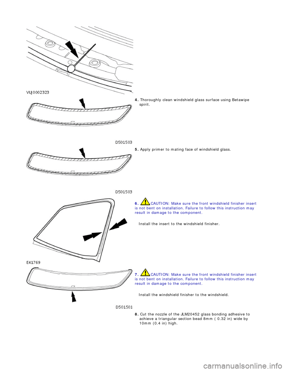
4. Thoroughly clean windshield glass surface using Betawipe
spirit.
5. Apply primer to mating fa ce of windshield glass.
6. CAUTION: Make sure the front windshield finisher insert
is not bent on installation. Failure to follow this instruction may
result in damage to the component.
Install the insert to the windshield finisher.
7. CAUTION: Make sure the front windshield finisher insert
is not bent on installation. Failure to follow this instruction may
result in damage to the component.
Install the windshield finisher to the windshield.
8. Cut the nozzle of the JLM20452 glass bonding adhesive to
achieve a triangular section bead 8mm ( 0.32 in) wide by
10mm (0.4 in) high.
Page 2217 of 2490
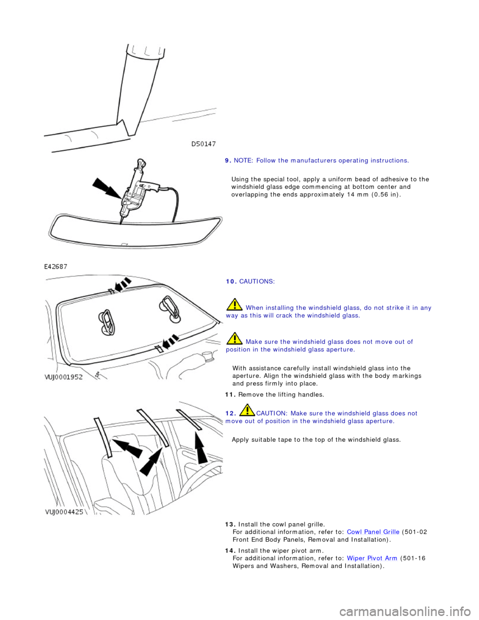
9. NOTE: Follow the manufacturers operating instructions.
Using the special tool, apply a uni form bead of adhesive to the
windshield glass edge commenc ing at bottom center and
overlapping the ends approximately 14 mm (0.56 in).
10. CAUTIONS:
When installing the windshield glass, do not strike it in any
way as this will crack the windshield glass.
Make sure the windshield glass does not move out of
position in the windshield glass aperture.
With assistance carefully install windshield glass into the
aperture. Align the windshield glass with the body markings
and press firmly into place.
11. Remove the lifting handles.
12. CAUTION: Make sure the windshield glass does not
move out of position in the windshield glass aperture.
Apply suitable tape to the to p of the windshield glass.
13. Install the cowl panel grille.
For additional information, refer to: Cowl Panel Grille (501-02
Front End Body Panels, Removal and Installation).
14. Install the wiper pivot arm.
For additional information, refer to: Wiper Pivot Arm
(501-16
Wipers and Washers, Remo val and Installation).
Page 2242 of 2490

Instrument Panel and Console - Instrument Panel
Removal and Installation
Removal
1. Turn ignition switch to position II.
2. Motor driver and front passenger seats rearward.
3. Position steering wheel in stra ight ahead position and fully
lower and extend steering column.
4. Turn ignition switch to position O.
5. Remove battery cover and disc onnect ground cable from
battery terminal. Refer to 86.15.19.
6. Remove 'J' gate finish er. Refer to 76.25.24.
7. Remove 'J' gate finisher retain ing panel. Refer to 76.25.26.
8. Remove centre console veneer panel. Refer to 76.47.26.
9. Disconnect and remove radio.
10. Remove centre console switch module. Refer to 86.80.32.
11. Remove centre console. Refer to 76.25.01.
12. Slacken and remove centre cons ole vent duct rear securing
screw and withdraw duct assemb ly from air conditioning unit
manifold.
13. WARNING: BEFORE ANY AIRBAG/SRS SERVICE IS
PERFORMED, AT LEAST ONE MINUTE MUST ELAPSE AFTER
DISCONNECTION OF THE BATTERY CABLE, TO ALLOW
DISSIPATION OF BACK-UP POWER SUPPLY ENERGY.
Remove driver airbag. Refer to 76.73.39.
14. Remove steering wheel. Refer to Section 211-04.
15. Remove steering column lo wer cowl. Refer to 76.46.03.
16. Remove steering column u pper cowl. Refer to 76.46.02.
17. Remove driver side unders cuttle. Refer to 76.46.11.
18. Remove combined windshield wiper/washer switch and
audible warning speaker assembly. Refer to 86.65.42.
19. Remove glovebox. Refer to 76.52.03.
20. Remove 'A' post lower trim pads. refer to 76.13.30.
21. Carefully withdraw driver stowage bin trim, remove bin
securing screw and remove bin from facia.