mirror JAGUAR X308 1998 2.G Workshop Manual
[x] Cancel search | Manufacturer: JAGUAR, Model Year: 1998, Model line: X308, Model: JAGUAR X308 1998 2.GPages: 2490, PDF Size: 69.81 MB
Page 26 of 2490

Side Turn Signal Lamp (86.41.41)
Side Turn Signal Lamp Bulb (86. 41.42)
417‐02
:
Interior Lighting
Specification
Description and Operation
Interior Lighting
Diagnosis and Testing
Interior Lighting
Removal and Installation
Door Courtesy Lamp (86.40.38)
Door Courtesy Lamp Bulb (86.40.47)
Door Courtesy Lamp Lens (86.40.35)
Glove Co
mpartment Lamp (86.45.08)
Luggage Compartment Lamp (86.45.16)
Vanity Mirror Lamp (76.10.50)
417‐04: Daytime Running Lamps (DRL)
Description and Operation
Daytime Running Lamps (DRL)
Diagnosis and Testing
Daytime Running Lamps (DRL)
418: Electrical Distribution
418‐00: Module Communications Network
Description and Operation
Communications Ne
twork
Removal
and Installation
Battery
Junction Box (BJB) (86.70.69)
Central
Junction Box (CJB) (86.70.72)
Front
Auxiliary Junction Box (86.70.73)
Rear
Auxiliary Junction Box (86.70.74)
418 ‐02: Wiring Harnesses
Description and Operati
on
Wiring Harness
General Procedures
Wiring Harness Repair
Page 29 of 2490

Parcel Shelf (76.67. 06)
Parcel Shelf
Support (76.67.09)
Passenger Assist Handle (76.58.30)
Rear Door Armrest (76.34.23)
Rear Door Trim Panel Finish Panel (76.47.12)
Rear Door Trim Panel (76.34.04)
Rear Window Blind (76.14.04)
Rear Door Window Control Switch Finish Panel (76.47.34)
Scuff Plate Trim Panel (76.13.81)
Sun Visor (76.10.48)
501‐08: Exterior Trim and Or
namentation
Description and Operation
Exterior Trim
Removal and Installation
A‐Pillar Moulding LH (76.13.19)
A‐Pillar Moulding RH (76.13.20)
Coachlines
Door Moulding (76.43.72)
Front Fender Moulding (76.10.48) (76.43.73)
Luggage Compartment Lid Badges (76.44.03)
Luggage Compartment Lid Moulding (76.43.79)
Radiator Grille (76.
55.03)
Radiator Grille Bezel (76.55.15)
501‐09: Rear View Mirrors
Description and Operation
Rear View Mirrors
Removal and Installation
Auto‐Dimming Interior Mirror (76.10.56)
Exterior Mirror (76.10.52)
Exterior Mirror Cover (76.10.55)
Exterior Mirror Glass (76.10.53)
Exterior Mirror Motor (76.10.57) (76.11.09)
Interior Mirror (76.10.51)
Interior Mirro
r Mounting Block (76.10.62)
Page 43 of 2490
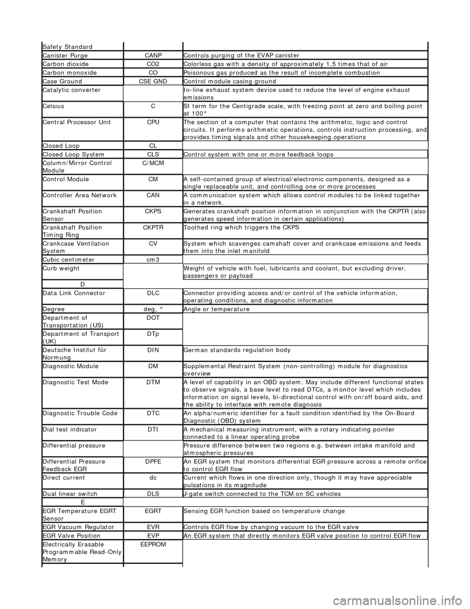
Safety Standard
Canister PurgeCANPControls pu
rging of the EVAP canister
Carbon dioxideCO2Colorless gas with
a density of a
pproximately 1.5 ti mes that of air
Carbon mon
oxide
COPoi
sonous gas produced as the re
sult of incomplete combustion
Case G
round
CSE GNDControl modu
le casing ground
Catal
ytic converter
In
-line exhaust system device used to reduce the level of engine exhaust
emissions
Ce
lsius
CSI ter
m for the Centigrade scale, with
freezing point at zero and boiling point
at 100°
Central
Processor Unit
CPUTh
e section of a computer that contai
ns the arithmetic, logic and control
circuits. It performs arithm etic operations, controls instruction processing, and
provides timing signals and other housekeeping operations
Cl
osed Loop
CL
Cl
osed Loop System
CLSControl
system with one
or more feedback loops
Col
umn/Mirror Control
Module
C/MC
M
Control ModuleCMA
self-contained group of electrical/electronic components, designed as a
single replaceable un it, and controlling one or more processes
Controll
er Area Network
CANA
communication system which allows control modules to be linked together
in a network.
Crankshaft Posi
tion
Sensor
CKPSGenerates crankshaft positi on informa
tion in conjunct
ion with the CKPTR (also
generates speed information in certain applications)
Crankshaft Posi
tion
Timing Ring
CKPT
R
Toothe
d ring which
triggers the CKPS
Crankcase Ventila
tion
System
CVSys
tem which scavenges camshaft cover and crankcase emissions and feeds
them into the inlet manifold
Cubic ce nt
imeter
cm
3
Curb weightWe
ight of vehicle with fuel, lubrican
ts and coolant, but excluding driver,
passengers or payload
D
Dat
a Link Connector
DLCConne
ctor providing access and/or control of the vehicle information,
operating conditions, and diagnostic information
De
gree
deg, °Angle or tempe
rature
D
epartment of
Transportation (US)
DO
T
D
epartment of Transport
(UK)
DTp
De
utsche In
stitut für
Normung
DINGerman stand
ards regulation body
Di
agnostic Module
DMSuppl
emental Restraint System (non-c
ontrolling) module for diagnostics
overview
Di
agnostic Test Mode
DTMA le
vel of capability in an OBD system.
May include different functional states
to observe signals, a base level to re ad DTCs, a monitor level which includes
information on signal levels, bi-directional control with on /off board aids, and
the ability to interface with remote diagnosis
Diagnostic Trouble CodeDTCAn al
pha/numeric identifier for a fault
condition identified by the On-Board
Diagnostic (OBD) system
D
ial test indicator
DTIA mechan
ical measuring
instrument, with a rotary indicating pointer
connected to a linear operating probe
D
ifferential pressure
Pressure di
fference betwee
n two regions e.g. between intake manifold and
atmospheric pressures
D
ifferential Pressure
Feedback EGR
DP
FE
An
EGR system that monito
rs differential EGR pressure across a remote orifice
to control EGR flow
D
irect current
dcCurrent which f
lows in on
e direction only, though it may have appreciable
pulsations in its magnitude
Du
al linear switch
DLSJ
-gate switch connected to the TCM on SC vehicles
E
EGR
Temperature EGRT
Sensor
EGRTSens
ing EGR function based on temperature change
EGR Vacu
um Regulator
EVRControls EGR
flow by changi
ng vacuum to the EGR valve
EGR Valve
Position
EVPAn EGR
system that direct
ly monitors EGR valve position to control EGR flow
Electrically E
rasable
Programmable Read-Only
Memory
EEP
ROM
Page 517 of 2490
o
perating. If an indicator bulb fails, the warning
lamp and ticking operate at twice the normal rate.
Sidelam
ps and Headlamps
Thes
e are controlled by rotating the end of the column switch as follows.
In the OFF position:
All
exterior lamps are switched OFF.
In the sidelamp position:
The front
sidelamps, tail, license plate and any other la
mps required by local legislation are switched ON.
The
sidelamps tell-tale lamp illuminates.
In the headlamp position, with the ignition switch in position II:
The h
eadlamps are switched ON in addition to the lamps switched on in the sidelamp position.
If the ignition is switched to the OFF position with the column switch in the headlamp position, the sidelamps, tail and
license plate lamps will stay ON, but the headlamps will switch OFF.
In the AUTO position (where fitted), with the ignition switch in position II:
Th
e sensor mounted on the back of the interior rear view
mirror monitors exterior light levels and automatically
switches the sidelamps and di pped headlamps ON and OFF.
The sensitivity level can be adjusted by turn ing the sensor control knob on the back of the interior mirror, left to decrease or
right to increase. The sensor must not be covered and the windscreen must be kept clean.
Headlamp Main Bea
m Position
Wi
th the column switch in
the headlamp position:
Movin
g the switch stalk away fro
m the steering wheel switches the headlamps to main beam.
Movin
g the switch stalk towards the steering wheel switches the headlamps to dipped beam.
The main beam tell-tale lamp illuminates when the headlamps are switched to main beam.
Ma
in Beam Flash
Wi
th the ignition switch and column switch in any position:
Pulling the
switch stalk agains
t spring pressure towards th e steering wheel illuminates the headlamps on main beam
for as long as the switch is held.
The main beam tell-tale lamp illuminates while the headlamps are illuminated.
M
essage Center Functions
T
he message center functions:
Are se
lected by the button located at the end of the lighting switch stalk.
Are se
lected in turn, by repeatedly pressing the button,
from the odometer reading, through the trip computer data
in sequence, and back to th e odometer reading again.
Page 549 of 2490
5.
Repeat steps 2 to 4 three
more times until all sixteen
valves on the first cylinder head have been adjusted.
6. Repeat steps 1 to 5 for the other cylinder head.
7. Remove all equipment and reassemble the engine.
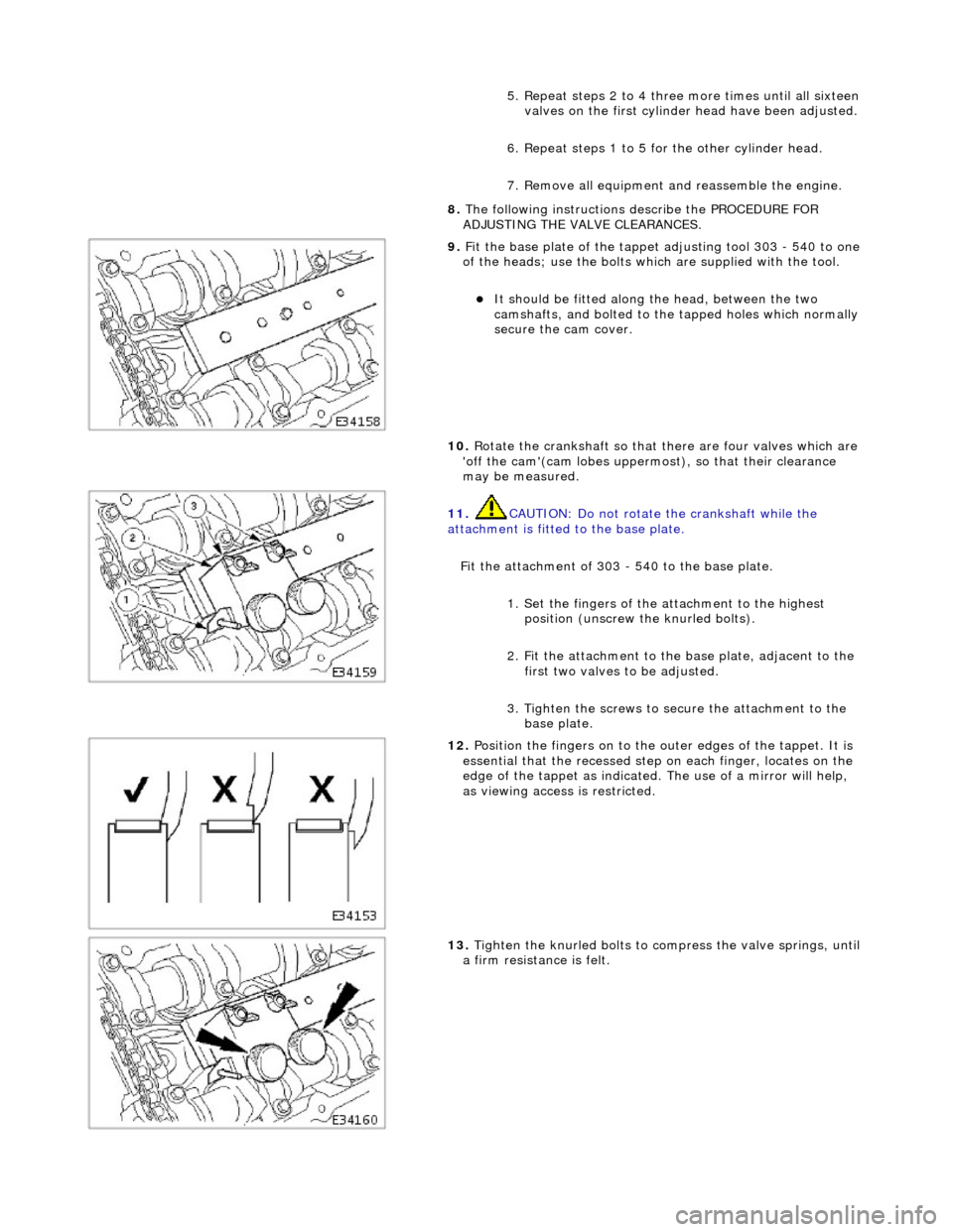
8. The following instructions describe the PROCEDURE FOR
ADJUSTING THE VALVE CLEARANCES.
9. F
it the base plate of the tappet
adjusting tool 303 - 540 to one
of the heads; use the bolts which are supplied with the tool.
It
should be fitted along the head, between the two
camshafts, and bolted to the tapped holes which normally
secure the cam cover.
10. Rotate the crankshaft so that there are four valves which are
'off the cam'(cam lobes uppermos t), so that their clearance
may be measured.
11
.
CAUTION: Do not rotate the crankshaft while the
attachment is fitted to the base plate.
Fit the attachment of 303 - 540 to the base plate. 1. Set the fingers of the attachment to the highest position (unscrew the knurled bolts).
2. Fit the attachment to the base plate, adjacent to the first two valves to be adjusted.
3. Tighten the screws to secure the attachment to the base plate.
12
.
Position the fingers on to the outer edges of the tappet. It is
essential that the recessed step on each finger, locates on the
edge of the tappet as indicated. The use of a mirror will help,
as viewing access is restricted.
13
.
Tighten the knurled bolts to compress the valve springs, until
a firm resistan ce is felt.
Page 1737 of 2490

I
nstallation
18
.
On non-ORVR vehicles, disconnect the trunk lid lefthand strut
rear pivot.
Pl
ace a suitable support under
trunk lid or tie to exterior
mirror.
1. Using a screwdriver, release clip at rear end of strut,
withdraw end from trunk lid pivot and lower strut.
19
.
Disconnect the tank ground cable from the vehicle body.
20. Remove the tank from the vehicle.
21. Drain any remaining fuel from the tank.
1. Fit the fuel tank assembly.
2. Re
-connect the tank ground cable to the vehicle.
Tigh
ten to 12 Nm.
3. On non-ORVR fuel tanks, positi on the trunk lid lefthand strut
between the filler tube and the breather pipe.
Page 1758 of 2490
Climate Control System - General Informatio
n - Climate Control System
D
iagn
osis and Testing
I
n
troduction
It is very i
m
portant to positive
ly identify the area of concern before starting a rectification procedure. A little time spent with
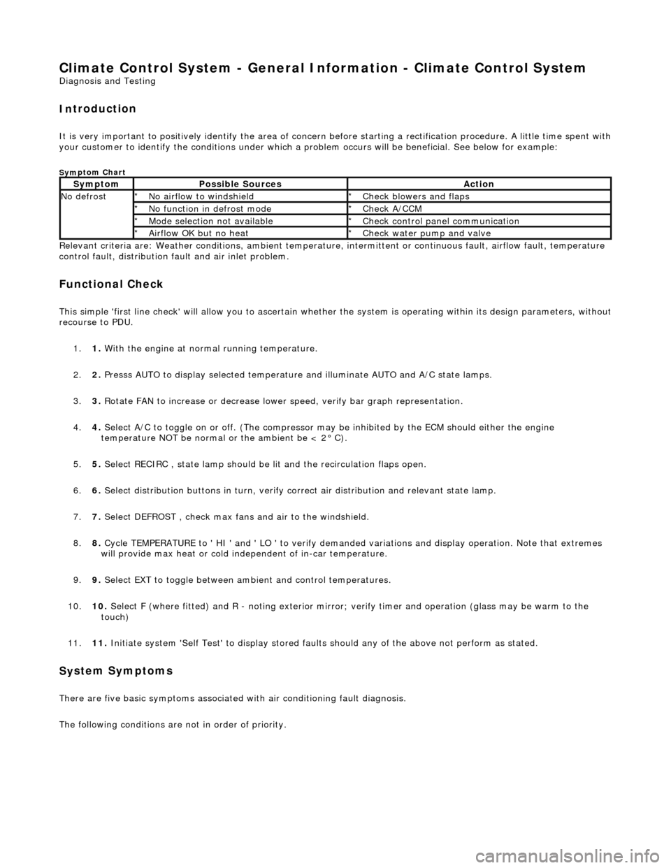
your customer to identify the conditions under which a pr oblem occurs will be beneficial. See below for example:
Sym
ptom Chart
Re
lev
ant criteria are: Weather conditions,
ambient temperature, intermittent or cont inuous fault, airflow fault, temperature
control fault, distribution fault and air inlet problem.
Functio n
al Check
This
s
imple 'first line check' will allo
w you to ascertain whether the system is operating within its design parameters, withou t
recourse to PDU.
1. 1. With the engine at normal running temperature.
2. 2. Presss AUTO to display selected temperature and illuminate AUTO and A/C state lamps.
3. 3. Rotate FAN to increase or decrease lowe r speed, verify bar graph representation.
4. 4. Select A/C to toggle on or off. (T he compressor may be inhibited by the ECM should either the engine
temperature NOT be normal or the ambient be < 2° C).
5. 5. Select RECIRC , state lamp should be lit and the recirculation flaps open.
6. 6. Select distribution butt ons in turn, verify correct air distribution and relevant state lamp.
7. 7. Select DEFROST , check max fans and air to the windshield.
8. 8. Cycle TEMPERATURE to ' HI ' and ' LO ' to verify demanded variations and display operation. Note that extremes
will provide max heat or cold independent of in-car temperature.
9. 9. Select EXT to toggle between am bient and control temperatures.
10. 10. Select F (where fitted) and R - noting exterior mirror; verify timer and operation (glass may be warm to the
touch)
11. 11. Initiate system 'Self Test' to display stored faul ts should any of the above not perform as stated.
Sy
stem Symptoms
There
are five
basic symptoms associated
with air conditioning fault diagnosis.
The following conditions are not in order of priority.
Sy m
ptom
Possib
l
e Sources
Acti
o
n
N
o defrostN o
airflow to windshield
*
Check blower s and flaps
*
N o functi
on in defrost mode
*
Check A/CCM
*
Mo de s
election not available
*
Chec k
control panel communication
*
Ai rfl
ow OK but no heat
*
Check water pu
mp and valve
*
Page 1824 of 2490
External temperature < -10 °C Vehicle speed > 65 km / h The first two conditions exist > 2 minutes. Engine speed > 50 revs / min
14. 14. Heated Backlight (R)
Pressing the heated backlight button will simultaneously energize the heater elements for timed cycles of;
21 minutes backlight 11 minutes exterior mirrors
Pressing the button again within the 21 minute timer will cancel the request.
If the engine is stalled, or the ignition switched OFF, the backlight and door mirror timers will be cleared, resulting in both
functions being switched off.
• NOTE: Both the backlight and door mirrors may be activated with the climate control system OFF, but the engine must be
running.
15. 15. Temperature Decrease
Pressing this button (BLUE symbol) decreases the interior temperature setting in 1° increments. Should the button be
pressed when the setting temperature is below the lower automatic control temperature limit, the display will indicate 'LO'.
16. 16. Temperature Increase
Pressing this button (RED symbol) will raise the temperature setting in 1° increments Should the button be pressed when
the setting temperature is above the upper automatic control temperature limit, the display will indicate 'HI'.
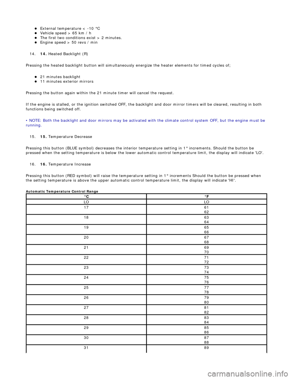
Automatic Temperature Control Range
°C°F
LOLO
1761
62
1863
64
1965
66
2067
68
2169
70
2271
72
2373
74
2475
76
2577
78
2679
80
2781
82
2883
84
2985
86
3087
88
3189
Page 1826 of 2490
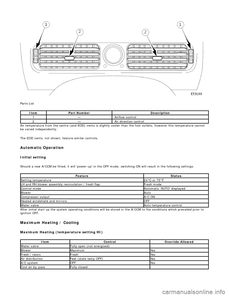
Parts List
Air temperature from the centre (and EOD) vents is slightly cooler than the foot outlets; however this temperature cannot
be varied independently.
The EOD vents, not shown, feature similar controls.
Automatic Operation
Initial setting
Should a new A/CCM be fitted, it will 'power-up' in the OFF mode; switching ON will result in the following settings:
After initial start up the system operating conditions will be st ored in the A/CCM to the conditions which prevailed prior to
ignition OFF.
Maximum Heating / Cooling
Maximum Heating (temperature setting HI)
ItemPart NumberDescription
1—Airflow control
2—Air direction control
FeatureStatus
Setting temperature24°C or 75°F
LH and RH blower assembly recirculation / fresh flapFresh mode
Control modeAutomatic 'AUTO' displayed
BlowerAuto
Compressor outputA/C ON
Heated windshield and mirrorsOFF
Water valveAuto temperature control
ItemControlOverride Allowed
Water valveFully open (not energised)-
BlowerMaximumYes
Fresh / recircFreshYes
Air distributionFeet (state lamp OFF)Yes
A/C systemOFFYes
Cool air by-passFully closed-
Page 1833 of 2490

Control Components - Control Components
Diagnosis and Testing
Connector Pin Identity Chart for AC001
Connector Pin Identity Chart for AC002
Pin NumberCircuitCircuit Function
001Compressor ON signal
002Coolant valve
003RH Blower motor relay
004Heated windshield relays (where fitted)
005Heated door mirror relay
006Defrost servomotor (positive)
007Center vent servomotor (positive)
008LH air intake servomotor fre sh / recirculation (positive)
009RH air intake servomotor fresh / recirculation (positive)
010Not used
011Not used
012Foot servomotor (positive)
013Cool air bypass servomotor (positive)
014Not used
015Not used
016LH Blower motor relay
017Coolant pump motor relay
018Heated backlight relay
019Defrost servomotor (negative)
020Center vent servomotor (negative)
021LH air intake servomotor fresh / recirculation (negative)
022RH air intake servomotor fresh / recirculation (negative)
023Not used
024Not used
025Foot servomotor (negative)
026Cool air bypass servomotor (negative)