check engine JAGUAR X308 1998 2.G Owner's Manual
[x] Cancel search | Manufacturer: JAGUAR, Model Year: 1998, Model line: X308, Model: JAGUAR X308 1998 2.GPages: 2490, PDF Size: 69.81 MB
Page 490 of 2490
Power Steering - Power Steering
Diagn
osis and Testing
Refer to the Description and Operation sub-section for details of the power operated steering system and Servotronic control
system.
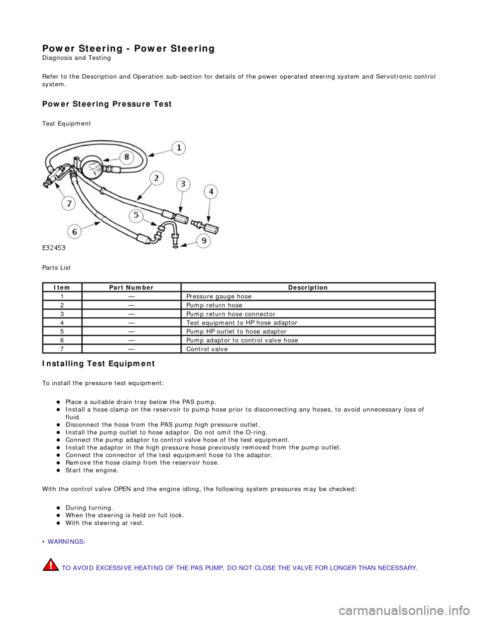
Power Steer ing Pressure Test
Test Equ
i
pment
Parts List
In
stalling Test Equipment
To
in
stall the pressure test equipment:
Pla
c
e a suitable drain tray below the PAS pump.
Install a hose clamp
on
the re
servoir to pump hose prior to disconnecting any hoses, to avoid unnecessary loss of
fluid.
Di sc
onnect the hose from the PAS pump high pres
sure outlet.
Ins
tall the pump outlet to hose ad
aptor. Do not omit the O-ring.
Conn
ect the pump adaptor to control valve hose of the test equipment.
Install th
e adaptor in the high pressure hose previ
ously re
moved from the pump outlet.
Conne
ct the connector of the test equipment hose to the adaptor.
R
e
move the hose clamp fro
m the reservoir hose.
Start th
e engine.
With the control valve OPEN and the engine idling , the following system pressures may be checked:
Du
ring turning.
W
h
en the steering is
held on full lock.
With
the steeri
ng at rest.
• WARNINGS:
TO AVOID EXCESSIVE HEATING OF THE PAS PUMP, DO NOT CLOSE THE VALVE FOR LONGER THAN NECESSARY.
Ite
m
Par
t
Number
De
scr
iption
1—Pressure
gauge hose
2—Pump return hose
3—Pump return hose connector
4—Test equi
pment to
HP hose adaptor
5—Pump HP outlet to hose adaptor
6—Pump adaptor
to control valve hose
7—Control valve
Page 548 of 2490
En
gine - Valve Clea
rance Adjustment
Gene
ral Procedures
S
p
ecial Tool(s)
Tappet adjustment
3
03-
540
Ai
r gun, fan nozzl
e
303-590
1. Open the engine compartment and fit paintwork protection
sheets. Open to the service position.
2. Carefully remove both engine covers, taking care not to
damage the plasti c fixings or the rubber inserts.
3. Disc
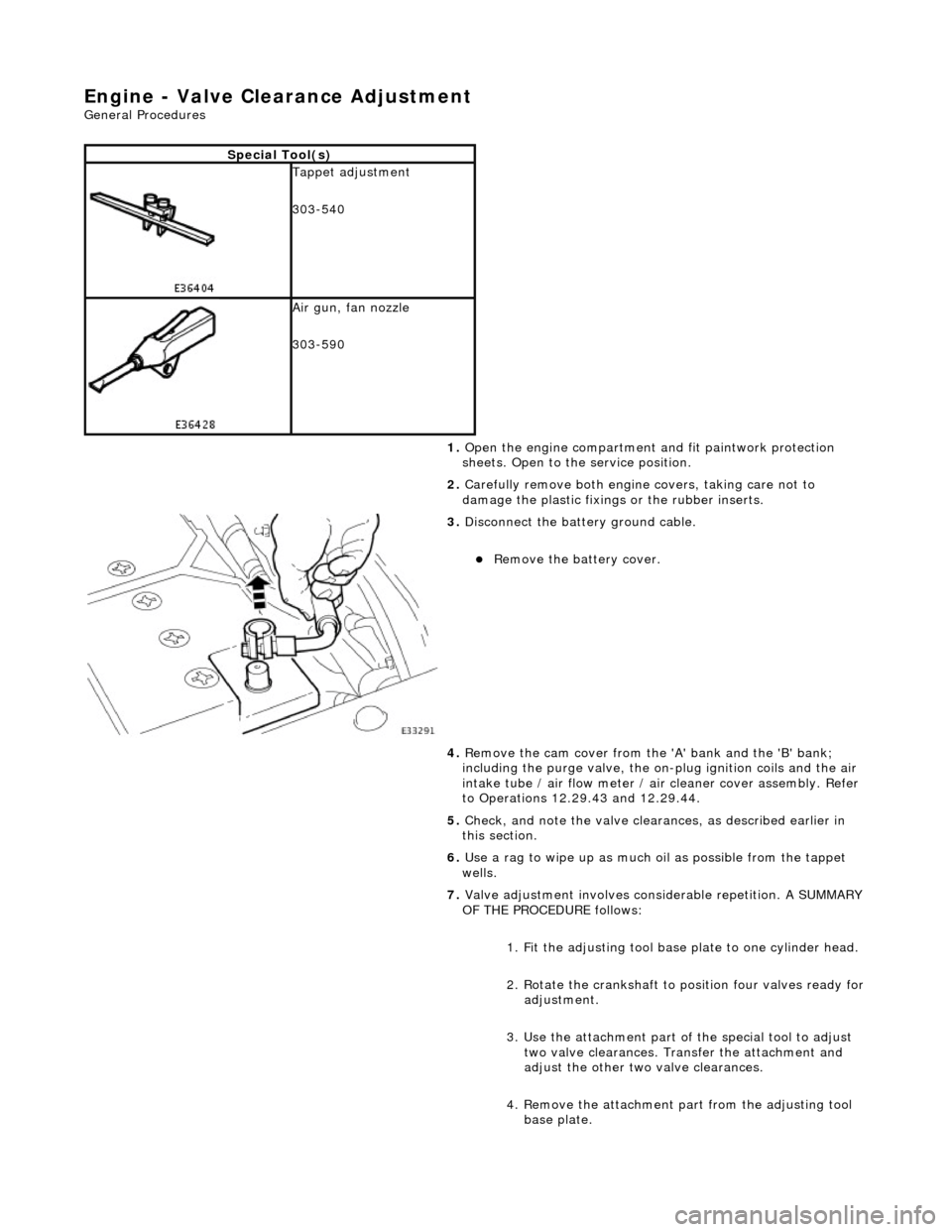
onnect the batt
ery ground cable.
Re
move the battery cover.
4. Remove the cam cover from the 'A' bank and the 'B' bank;
including the purge valve, the on-plug ignition coils and the air
intake tube / air flow meter / air cleaner cover assembly. Refer
to Operations 12.29.43 and 12.29.44.
5. Check, and note the valve cleara nces, as described earlier in
this section.
6. Use a rag to wipe up as much oil as possible from the tappet
wells.
7. Valve adjustment involves considerable repetition. A SUMMARY
OF THE PROCEDURE follows:
1. Fit the adjusting tool base plate to one cylinder head.
2. Rotate the crankshaft to position four valves ready for
adjustment.
3. Use the attachment part of the special tool to adjust two valve clearances. Transfer the attachment and
adjust the other two valve clearances.
4. Remove the attachment pa rt from the adjusting tool
base plate.
Page 550 of 2490
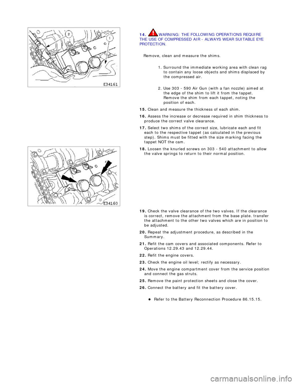
14
. WARNING: TH
E FOLLOWING OPERATIONS REQUIRE
THE USE OF COMPRESSED AIR - ALWAYS WEAR SUITABLE EYE
PROTECTION.
Remove, clean and measure the shims.
1. Surround the immediate wo rking area with clean rag
to contain any loose objects and shims displaced by
the compressed air.
2. Use 303 - 590 Air Gun (with a fan nozzle) aimed at the edge of the shim to lift it from the tappet.
Remove the shim from each tappet, noting the
position of each.
15 . Cl
ean and measure the thickness of each shim.
16. Assess the increase or decrease required in shim thickness to
produce the correct valve clearance.
17. Select two shims of the correct size, lubricate each and fit
each to the respective tappet (as calculated in the previous
step). Shims must be fitted with the size marking facing the
tappet NOT the cam.
18 . Loos
en the knurled screws on 303 - 540 attachment to allow
the valve springs to return to their normal position.
19. Check the valve clearance of the two valves. If the clearance
is correct, remove the attachment from the base plate. transfer
the attachment to the other two valves which are in position to
be adjusted.
20. Repeat the adjustment procedure, as described in the
Summary.
21. Refit the cam covers and associated components. Refer to
Operations 12.29.43 and 12.29.44.
22. Refit the engine covers.
23. Check the engine oil level; rectify as necessary.
24. Move the engine compartment cover from the service position
and connect the gas struts.
25. Remove the paint protection sheets and close the cover.
26. Connect the battery and fit the battery cover.
Refe
r to the Battery Reconnection Procedure 86.15.15.
Page 551 of 2490
E
ngine - Valve Clearance Check
Gen
eral Procedures
1.
Open the engine compartment and fit paintwork protection
sheets. Open to the service position.
2. Carefully remove both engine covers, taking care not to
damage the plasti c fixings or the rubber inserts.
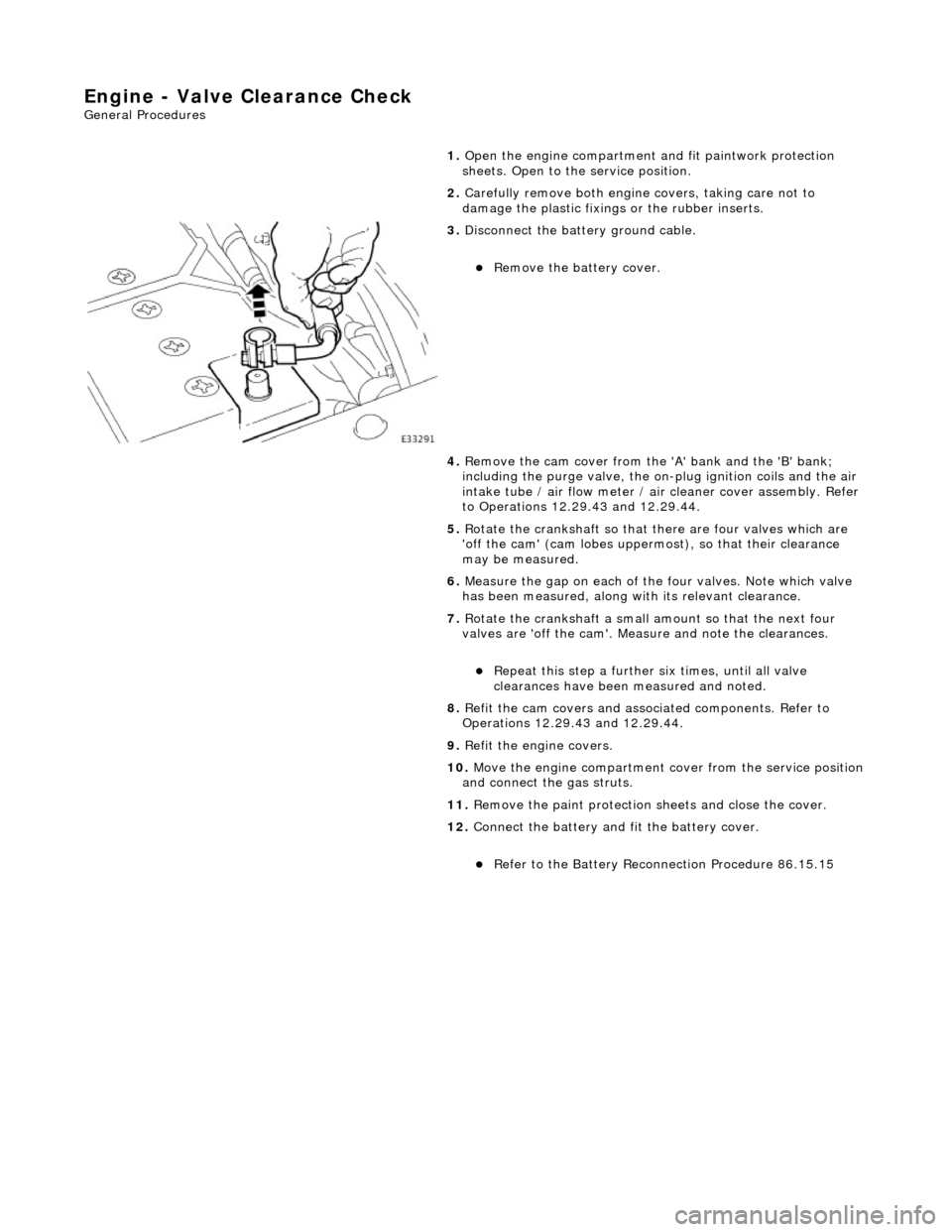
3. Di
sconnect the batt
ery ground cable.
R
emove the battery cover.
4. Remove the cam cover from the 'A' bank and the 'B' bank;
including the purge valve, the on-plug ignition coils and the air
intake tube / air flow meter / air cleaner cover assembly. Refer
to Operations 12.29.43 and 12.29.44.
5. Rotate the crankshaft so that there are four valves which are
'off the cam' (cam lobes upperm ost), so that their clearance
may be measured.
6. Measure the gap on each of the four valves. Note which valve
has been measured, along with its relevant clearance.
7. Rotate the crankshaft a small am ount so that the next four
valves are 'off the cam'. Measure and note the clearances.
Re
peat this step
a further six times, until all valve
clearances have been measured and noted.
8. Refit the cam covers and associated components. Refer to
Operations 12.29.43 and 12.29.44.
9. Refit the engine covers.
10. Move the engine compartment cover from the service position
and connect the gas struts.
11. Remove the paint protection sheets and close the cover.
12. Connect the battery and fit the battery cover.
Re
fer to the Battery Reconnection Procedure 86.15.15
Page 556 of 2490
5.
Install the front cros smember. Refer to Operat
ion 76.10.05.
6. Install the undert ray. Refer to Operation 76.22.90.
7. Install both front wheel and tyre assemblies. Refer to
Operation 74.20.05.
8. Install the timing cover and al l associated components, as
detailed in Operation 12.65.01.
9. Install the twin fan and motor assembly. Refer to Operation
26.25.12.
10. NOTE: When the engine is star ted from cold and run for a
short period only, before being swit ched off, a quantity of oil will
be 'hung up' within the engine because it is not up to operating
temperature.
Should the oil level subsequently be topped-up, the level could
become too high, causing oil burning.
Typically, 0.875 L is hung up.
Refill the engine with the correct specification engine oil.
11. Connect the battery and in stall the battery cover.
Refe
r to the Battery Reconnection Procedure 86.15.15.
12. Check the oil level and start th e engine. Check for leaks and
that the engine runs correctly.
13. Install the engine compartmen t cover. Refer to operation
76.16.01.
14. Remove the paintwork protection sheets and close the engine
compartment cover.
Page 584 of 2490
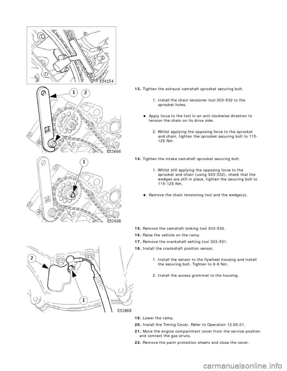
13. Tigh
ten the exhaust camshaft
sprocket securing bolt.
1. Install the chain tensioner tool 303-532 to the sprocket holes.
Appl y force
to the tool in an
anti-clockwise direction to
tension the chain on its drive side.
2. Whilst applying the opposing force to the sprocket and chain, tighten the sprock et securing bolt to 115-
125 Nm.
14 .
Tigh
ten the intake camshaft
sprocket securing bolt.
1. Whilst still applying the opposing force to the
sprocket and chain (using 303-532), check that the
wedges are still in place, ti ghten the securing bolt to
115-125 Nm.
R e
move the chain tensioning
tool and the wedge(s).
15. Remove the camshaft locking tool 303-530.
16. Raise the vehicle on the ramp.
17. Remove the crankshaft setting tool 303-531.
18 . Inst
all the crankshaft position sensor.
1. Install the sensor to the flywheel housing and install
the securing bolt. Tighten to 6-8 Nm.
2. Install the access grommet to the housing.
19. Lower the ramp.
20. Install the Timing Cover. Refer to Operation 12.65.01.
21. Move the engine compartment cover from the service position
and connect the gas struts.
22. Remove the paint protection sheets and close the cover.
Page 592 of 2490

2.
Fit a new O-ring to the carrier oil-way.
14. F
it the VVT bush carrier to the cylinder block.
Lubric
ate the seal (scarf
jointed) and the bush.
1. Fit the bush carrier assembly.
Check that th e seals are in pl ace an
d that the ring dowels
are engaged squarely. Fully locate the assembly as much
as possible by hand pressure.
2. Fit the three securing bolts. Tighten to 19-23 Nm.
15. Refit the Timing Cover. Refer to Operation 12.65.01 in this
Section.
16. Move the engine compartment cover from the service position
and connect the gas struts.
17. Remove the paint protection sheets and close the cover.
18. Connect the battery and fit the battery cover.
Refe
r to the Battery Reconnection Procedure in Section
414-01.
Page 607 of 2490
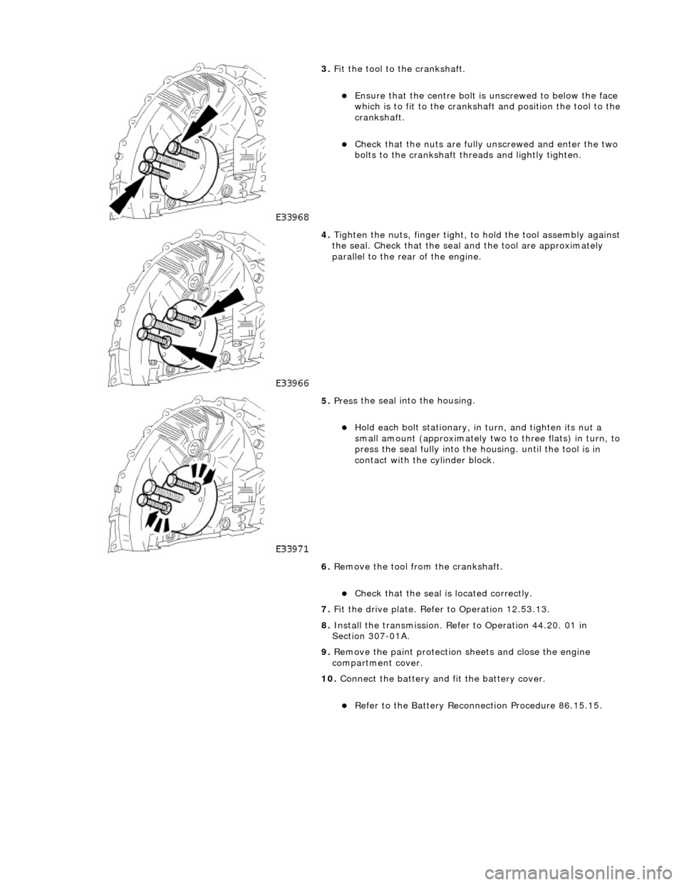
3.
F
it the tool to the crankshaft.
E
nsure that the cent
re bolt is unscrewed to below the face
which is to fit to the crankshaft and position the tool to the
crankshaft.
Chec
k that the nuts are fully unscrewed and enter the two
bolts to the crankshaft thre ads and lightly tighten.
4. Tigh
ten the nuts, finger tight, to hold the tool assembly against
the seal. Check that the seal and the tool are approximately
parallel to the rear of the engine.
5. Pres
s the seal into the housing.
Ho
ld each bolt stationary, in
turn, and tighten its nut a
small amount (approximately two to three flats) in turn, to
press the seal fully into the housing. until the tool is in
contact with the cylinder block.
6. Remove the tool from the crankshaft.
Chec
k that the seal is located correctly.
7. Fit the drive plate. Refer to Operation 12.53.13.
8. Install the transmission. Refer to Operation 44.20. 01 in
Section 307-01A.
9. Remove the paint protection sheets and close the engine
compartment cover.
10. Connect the battery and fit the battery cover.
Re
fer to the Battery Reconnection Procedure 86.15.15.
Page 610 of 2490
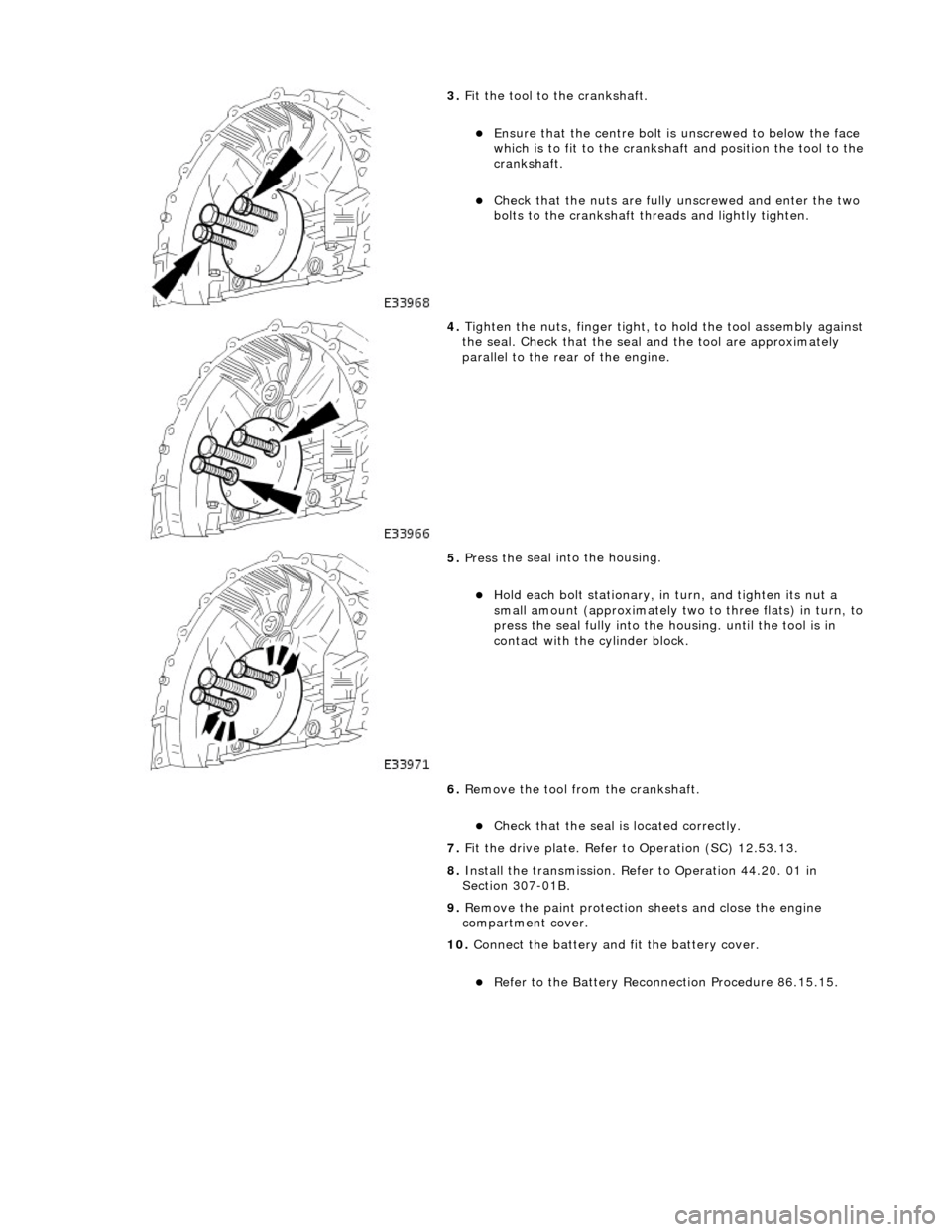
3.
Fit
the tool to the crankshaft.
En
sure that the cent
re bolt is unscrewe d to below the face
which is to fit to the crankshaft and position the tool to the
crankshaft.
Chec k that
the nuts are fully unscrewed and enter the two
bolts to the crankshaft thre ads and lightly tighten.
4. Tight
en the nuts, finger tight, to hold the tool assembly against
the seal. Check that the seal and the tool are approximately
parallel to the rear of the engine.
5. Pres s th
e seal into the housing.
Ho
ld e
ach bolt stationary, in
turn, and tighten its nut a
small amount (approximately two to three flats) in turn, to
press the seal fully into the housing. until the tool is in
contact with the cylinder block.
6. Remove the tool from the crankshaft.
Chec k that
the seal is located correctly.
7. Fit the drive plate. Refer to Operation (SC) 12.53.13.
8. Install the transmission. Refer to Operation 44.20. 01 in
Section 307-01B.
9. Remove the paint protection sheets and close the engine
compartment cover.
10. Connect the battery and fit the battery cover.
Re
fe
r to the Battery Reconnection Procedure 86.15.15.
Page 633 of 2490

I
dentify the VCT oil supply gallery and the 8 mm blind rivet.
U
sing a suitable 3 mm punch release the centre of the blind rivet until
it is released from the outer part of the blind rivet.
U
sing a suitable extraction tool, remo
ve the remaining part of the blind
rivet.
2. Clean the component mating faces.
3.
Check cylinder head face for distortio
n, across the center and from corner
to corner.
4. For cylinder head face distortion data, refer to specifications.For additional
information, refer to: Specifications
(303
-00 Engine System - General
Information, Specifications).
5.
NOTE: For
cylinder head with
distortion above the
maximum allowance,
the cylinder head
material must be
measured.
Measure the
cylinder head
material.
Che
ck
measurement
from the
centre of the
exhaust
dowel to the
cylinder head
face as
shown.
If the
measurement
is less than
51.88 mm
the cylinder
head requires
replacement.
6.
Install a new gasket to the downpipe catalyst flange.
7. Install and align a new cylinder head gasket to the cylinder block face.