replace battery JAGUAR X308 1998 2.G Owner's Manual
[x] Cancel search | Manufacturer: JAGUAR, Model Year: 1998, Model line: X308, Model: JAGUAR X308 1998 2.GPages: 2490, PDF Size: 69.81 MB
Page 1433 of 2490

Automatic Transmission/Transaxle - 4.0L SC V8 - AJ26 - Extension
Housing Seal
In-vehicle Repair
Removal
Special Tool(s)
Oil seal replacer
307-378
Driveshaft wrench
205-053
1. Disconnect the battery ground lead.
2. Select N and choc the road wheels.
3. Remove the front muffler, re fer to Operation 30.10.18.
4. Remove the engine rear mounting bracket.
1. Support the transmission.
2. Remove the bolt, engine rear mounting to transmission.
3. Remove the four bolts which secure the mounting
cross member to the body.
5. Detach the driveshaft from th e transmission drive flange.
1. If the transmission is to be refitted, mark the position of the coupling relative to the drive flange.
5. CAUTION: Under no circ umstances remove the
driveshaft to flexible coupling fixings.
2. Remove the three bolts, tr ansmission drive flange to
flexible coupling.
6. Secure the driveshaft wrench 205 - 053 to the output shaft
flange.
Page 1456 of 2490

Automatic Transmission/Transaxle - 4.0L SC V8 - AJ26 - Input Shaft Seal
Disassembly and Assembly of Subassemblies
Special Tool(s)
Oil seal replacer
307-378
1. Disconnect the battery ground lead.
2. Remove the air intake / MAFM assembly, refer to Operation
19.10.30.
3. Raise the vehicle for access.
4. Remove the front muffler, 30.10.18
5. Remove the RH and LH catalytic converters, refer to Operation
17.50.09 and 17.50.10.
6. Drain the transmission fluid, refer to Operation 44.24.02.
7. Remove the transmission unit, refer to Operation 44.20.01.
8. Remove the torque converter fro m the transmission unit, refer
to Operation 44.17.07.
9. Remove the front oil seal.
Using a proprietary tool remove the seal, taking care not
to damage the shaft or bore diameters.
10. Installation is the reverse of the removal procedure noting
that:
11. Fit the oil seal.
1. Lubricate the housing seal bore.
2. Lubricate the outside diameter of the seal.
3. Using seal replacer 307 - 379, drive the seal squarely into place.
Page 1700 of 2490

Wi
th EM013 disconnected, check for battery voltage
between EM013/001 and ground BT020L.
1
B+ ?
Yes
GO t
o A13
No GO to A4
A4: CHECK
SUPPLY VOLTAGE
•
NOTE: Do not replace relay.
Page 1701 of 2490

W
ith relay 4 removed, check for battery voltage at relay
socket between pins 3 and 5.
1
B+
Yes GO to A5
No GO to A11
A5
: CHECK CIRCUIT CONTINUITY
•
NOTE: Do not replace relay.
Page 1712 of 2490
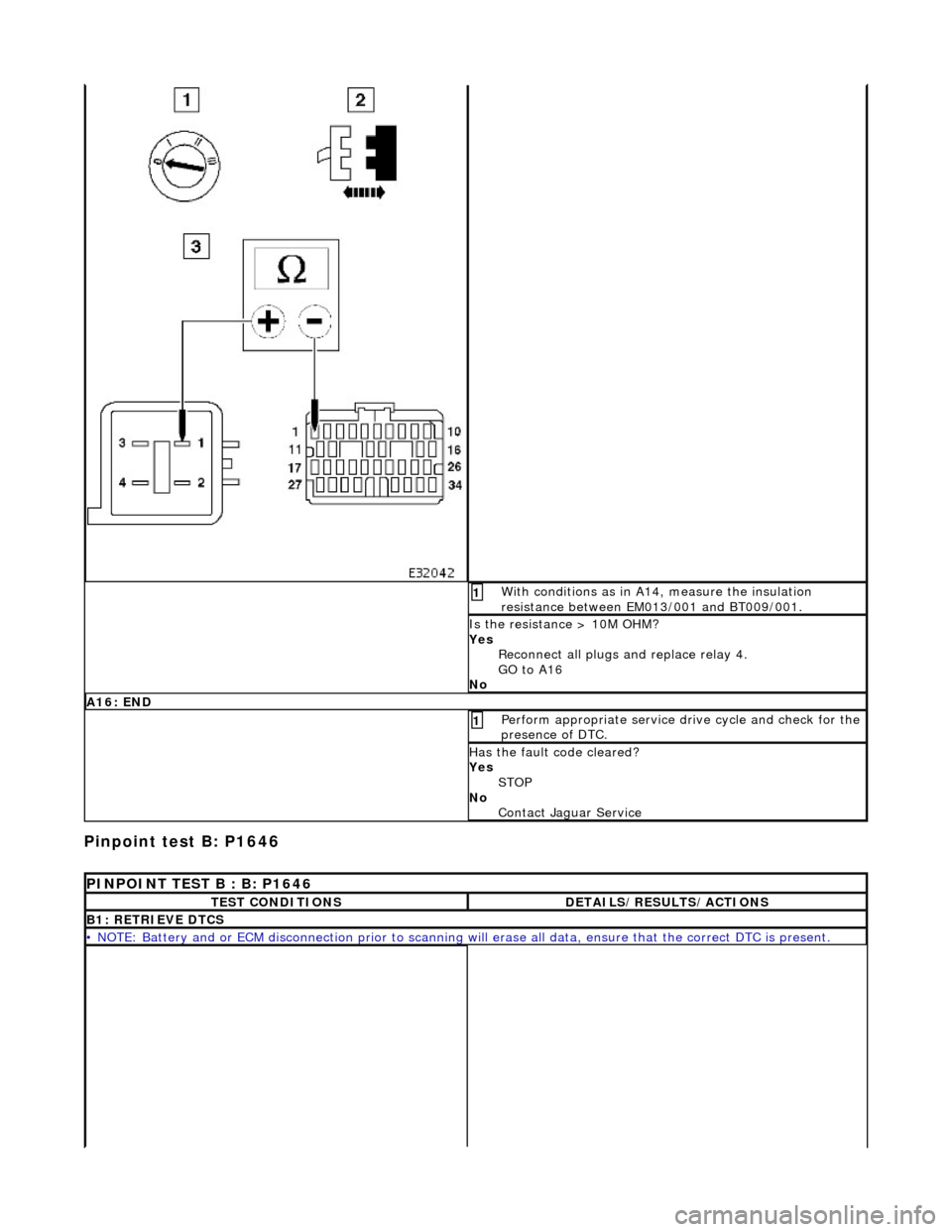
Pinpoint test B:
P1646
W
i
th conditions as in A14, measure the insulation
resistance between EM013/001 and BT009/001.
1
I s
the resistance > 10M OHM?
Yes Reconnect all plugs and replace relay 4.
GO to A16
No
A 16:
END
Perform
a
ppropriate service drive cycle and check for the
presence of DTC.
1
Has th
e fault code cleared?
Yes STOP
No Contact Ja
guar Serv ice
PINPOINT TEST B : B: P1646
TE
ST CONDITIONS
D
E
TAILS/RESULTS/ACTIONS
B1
: RETRI
EVE DTCS
•
NOTE
: Battery and or ECM disconnection prior to scanning wi
ll erase all data, ensure that the correct DTC is present.
Page 1714 of 2490
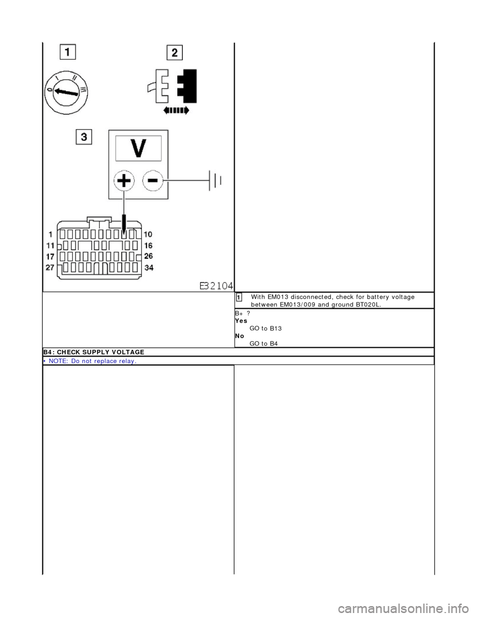
Wi
th EM013 disconnected, check for battery voltage
between EM013/009 and ground BT020L.
1
B+ ?
Yes
GO t
o B13
No GO to B4
B4: CHECK
SUPPLY VOLTAGE
•
NOTE: Do not replace relay.
Page 1715 of 2490

W
ith relay 1 removed, check for battery voltage at relay
socket between pins 3 and 5.
1
B+
Yes GO to B5
No GO to B11
B5
: CHECK CIRCUIT CONTINUITY
•
NOTE: Do not replace relay.
Page 1726 of 2490
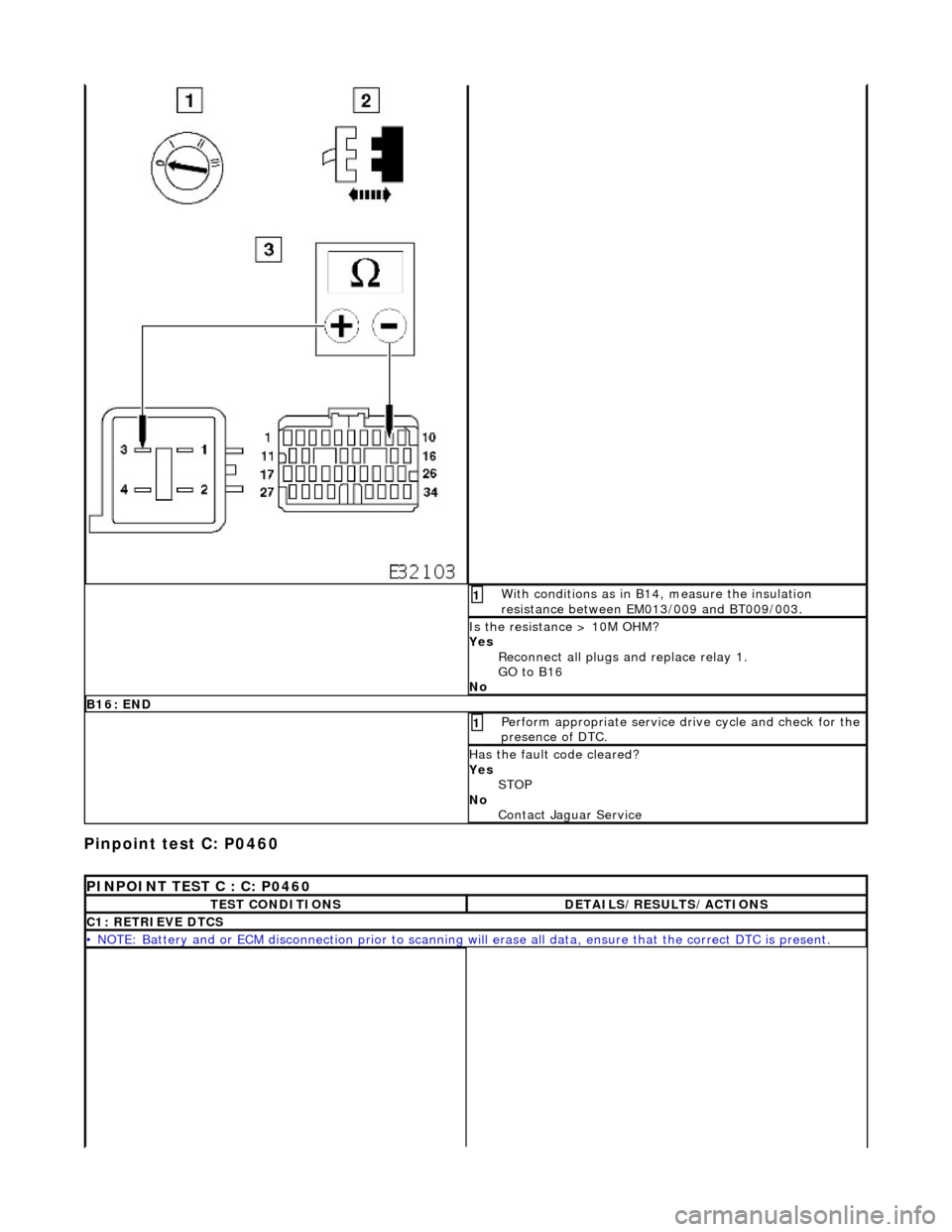
Pinpoint test C: P0460
Wi
th conditions as in B14, measure the insulation
resistance between EM013/009 and BT009/003.
1
I s
the resistance > 10M OHM?
Yes Reconnect all plugs and replace relay 1.
GO to B16
No
B 16:
END
Perform
a
ppropriate service drive cycle and check for the
presence of DTC.
1
Has th
e fault code cleared?
Yes STOP
No Contact Jaguar Service
PI
NPOINT TEST C : C: P0460
T
E
ST CONDITIONS
D
E
TAILS/RESULTS/ACTIONS
C1
: RETRIEVE DTC
S
•
NOTE
: Battery and or ECM disconnection prior to scanning wi
ll erase all data, ensure that the correct DTC is present.
Page 1762 of 2490
Climate Control System - General Infor
mation - Air Conditioning (A/C)
System Recovery, Evacuation and Charging
Gen e
ral Procedures
Recover / Reclaim
Ev
acuation
Charging
1.
CAUTIO
N: Read the procedures and instructions supplied
by the manufacturer of the air co nditioning service center before
commencing any process requiring the handling of refrigerant. In
addition to the manufacturer's in formation, observe all safety
precautions and advice deta iled in this section.
Disconnect battery ground lead; refer to 86.15.19.
2. Remove passenger side fi
rewall cover.
3. Remove driver side firewall cover.
4. Remove engine compar tment rear cover.
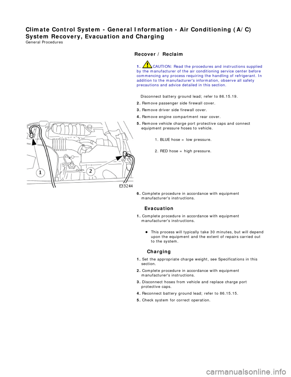
5. Re
move vehicle charge port
protective caps and connect
equipment pressure hoses to vehicle.
1. BLUE hose = low pressure.
2. RED hose = high pressure.
6. Complete procedure in ac cordance with equipment
manufacturer's instructions.
1. Complete procedure in ac cordance with equipment
manufacturer's instructions.
This proc
ess will typically ta
ke 30 minutes, but will depend
upon the equipment and the ex tent of repairs carried out
to the system.
1. Set the appropriate charge weight, see Specifications in this
section.
2. Complete procedure in ac cordance with equipment
manufacturer's instructions.
3. Disconnect hoses from vehicle and replace charge port
protective caps.
4. Reconnect battery ground lead; refer to 86.15.15.
5. Check system for correct operation.
Page 1973 of 2490
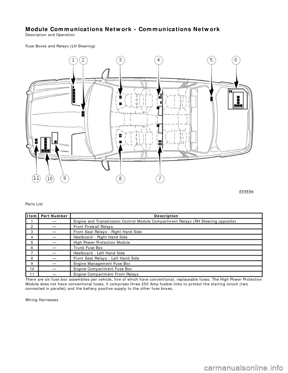
Module Communications Network - Communications Network
Description and Operation
Fuse Boxes and Relays (LH Steering)
Parts List
There are six fuse box assemblies per vehicle, five of which have conventional, replaceable fuses. The High Power Protection
Module does not have conventional fuses, it comprises three 250 Amp fusible links to protect the starting circuit (two
connected in parallel) and the battery positive supply to the other fuse boxes.
Wiring Harnesses
ItemPart NumberDescription
1—Engine and Transmission Cont rol Module Compartment Relays (RH Steering opposite)
2—Front Firewall Relays
3—Front Seat Relays - Right Hand Side
4—Heelboard - Right Hand Side
5—High Power Protection Module
6—Trunk Fuse Box
7—Heelboard - Left Hand Side
8—Front Seat Relays - Left Hand Side
9—Engine Management Fuse Box
10—Engine Compartment Fuse Box
11—Engine Compartment Front Relays