replace battery JAGUAR X308 1998 2.G User Guide
[x] Cancel search | Manufacturer: JAGUAR, Model Year: 1998, Model line: X308, Model: JAGUAR X308 1998 2.GPages: 2490, PDF Size: 69.81 MB
Page 445 of 2490
Anti-Lock Control - Hydraulic Contro
l Unit (HCU)
Re
moval and Installation
Remov
al
• C
AUTIONS:
Replacement of nuts and bolts: Various thread-locking de vices are used on nuts and bolts throughout the vehicle.
These devices restrict the number of times a nut or bolt can be used. See section 100-00 for information.
Remove brake fluid spilla ge immediately from paint work, with clean water.
S
pecial Tool(s)
Brake Pedal
Hold Tool
JDS 9013
1. Disc
onnect battery ground cable (IMPORTANT, see operation
86.15.19 for further information).
2. Position vehicle on a four-post lift.
3. Open engine compartment and fit paint work protection covers
to fenders.
4. NOTE
: The following three pictorial procedures must be
carried-out to minimize brake fl uid loss when disconnecting the
brake tubes.
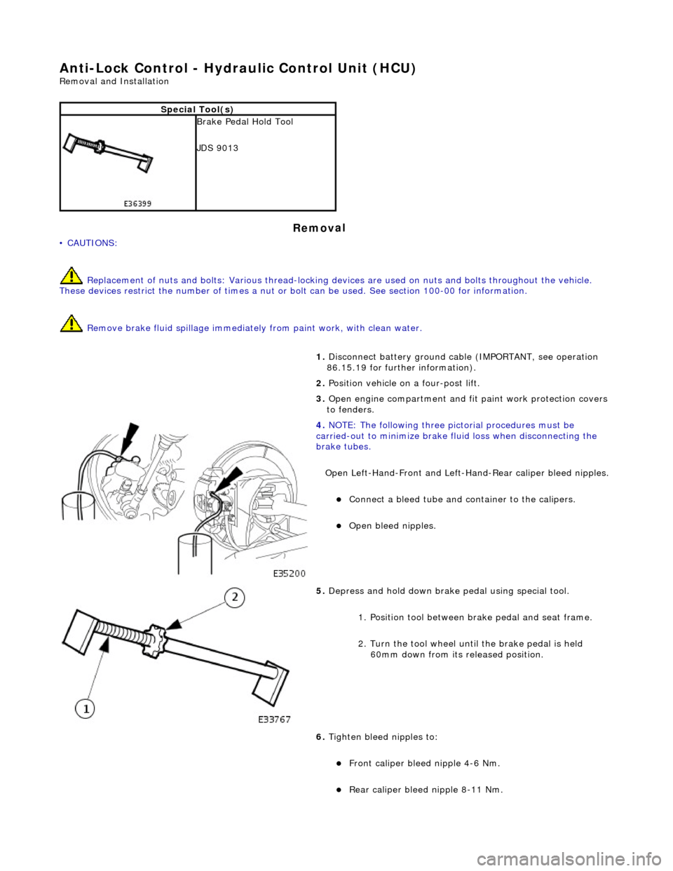
Open Left-Hand-Front and Left-H and-Rear caliper bleed nipples.
Connect
a bleed tube and co
ntainer to the calipers.
O
pen bleed nipples.
5. Depress and hold down brake pedal u
sing special tool.
1. Position tool between brake pedal and seat frame.
2. Turn the tool wheel unti l the brake pedal is held
60mm down from its released position.
6. Tighten bleed nipples to:
Front caliper blee d nipple 4-6
Nm.
Rear
caliper bleed nipple 8-11 Nm.
Page 605 of 2490

Engine - Crankshaft
Rear Seal4.0L
NA V8 - AJ27/3.2 L NA V8 - AJ26
In-v
ehicle Repair
Remov
al
S
pecial Tool(s)
Crankshaft Rear Oi
l Seal Remover /
Replacer.
303 - 538
1. Open the engine compartment and fit paint protection sheets.
2. Di
sconnect the batt
ery ground cable.
R
emove the battery cover.
3. Remove the transmission. Refer to Operation 44.20. 01 in
Section 307-01A.
4. Remove the drive plate. Refer to Operation 12.53.13.
5. F
it and align the seal removal tool 303 - 538 to the crankshaft.
1. Unscrew the two nuts towards the head of each bolt to allow the bolts to fit fully into the crankshaft.
2. Unscrew the center bolt until it is below the face of the main tool and position the tool to the rear of the
crankshaft.
3. Lightly tighten the two bolts so that they fully locate in the crankshaft.
6. Hold the tool against th
e cran
kshaft and lightly and evenly
tighten the two nuts to the face of the tool; to secure the tool
and to hold it parallel to the face of the crankshaft.
7. Secure the oil seal to the tool using the three self-tapping
Page 608 of 2490

Engine - Crankshaft Rear Seal4.0L SC V8 - AJ26
In-vehic
le Repair
Remov
a
l
S
p
ecial Tool(s)
Crankshaft Rear Oi
l Seal R
emover /
Replacer.
303 - 538
1. Open the engine compartment and fit paint protection sheets.
2. Disc
onnect the batt
ery ground cable.
Re
move the battery cover.
3. Remove the transmission. Refer to Operation 44.20. 01 in
Section 307-01B.
4. Remove the drive plat e. Refer to Operation (SC) 12.53.13.
5. Fi
t and align the seal removal tool 303 - 538 to the crankshaft.
1. Unscrew the two nuts towards the head of each bolt to allow the bolts to fit fully into the crankshaft.
2. Unscrew the center bolt until it is below the face of the main tool and position the tool to the rear of the
crankshaft.
3. Lightly tighten the two scre ws so that they fully locate
in the crankshaft.
6. Hold the tool against th e cr
an
kshaft and lightly and evenly
tighten the two nuts to the face of the tool; to secure the tool
and to hold it parallel to the face of the crankshaft.
7. Secure the oil seal to the tool using the three self-tapping
Page 611 of 2490
E
ngine - Cylinder Head LH
In-ve
hicle Repair
Remova
l
CAU
TION: If a replacement cylinder head is to be installed to a
vehicle with variable camshaft timing (VCT) the cylinder head m ust have the
oil gallery blind rivet removed before installation.
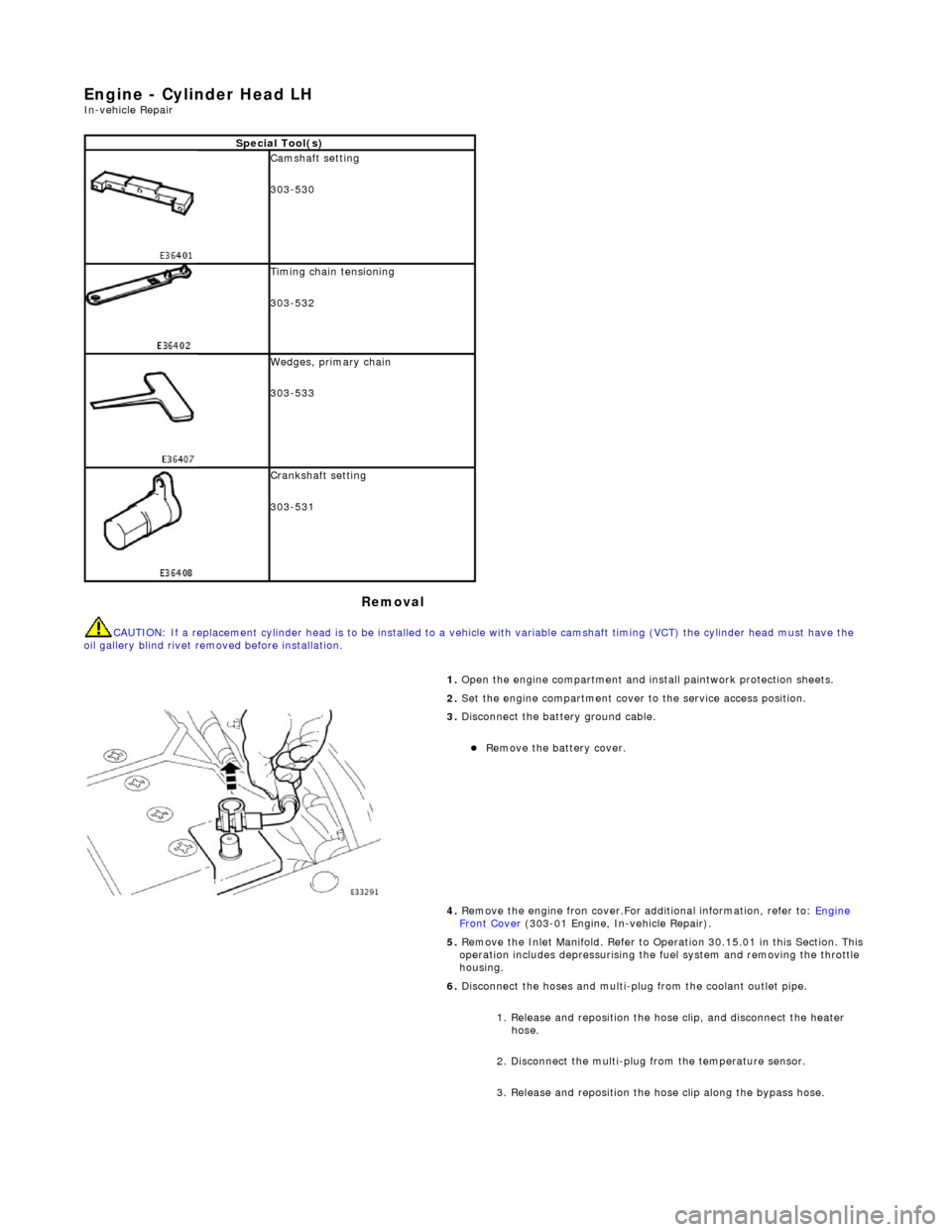
Spe
cial Tool(s)
Cams
haft setting
303-530
Ti
ming chain tensioning
303-532
Wedges, prim
ary chain
303-533
Cr
ankshaft setting
303-531
1.
Open the engine compartment and install paintwork protection sheets.
2. Set the engine compartment cover to the service access position.
3.
Disconnect the battery ground cable.
Re
move the battery cover.
4. Remove the engine fron cover.For additional information, refer to: Engine
Front Cover (303-01 Engi
ne, In-vehicle Repair).
5. Remove the Inlet Manifold. Refer to Operation 30.15.01 in this Section. This operation includes depressurising the fuel system and removing the throttle
housing.
6. Disconnect the hoses and multi-plug from the coolant outlet pipe.
1. Release and reposition the hose clip, and disconnect the heater hose.
2. Disconnect the multi-plug from the temperature sensor.
3. Release and reposition the hose clip along the bypass hose.
Page 627 of 2490
E
ngine - Cylinder Head RH
In-ve
hicle Repair
Remova
l
CAU
TION: If a replacement cylinder head is to be installed to a
vehicle with variable camshaft timing (VCT) the cylinder head m ust have the
oil gallery blind rivet removed before installation.
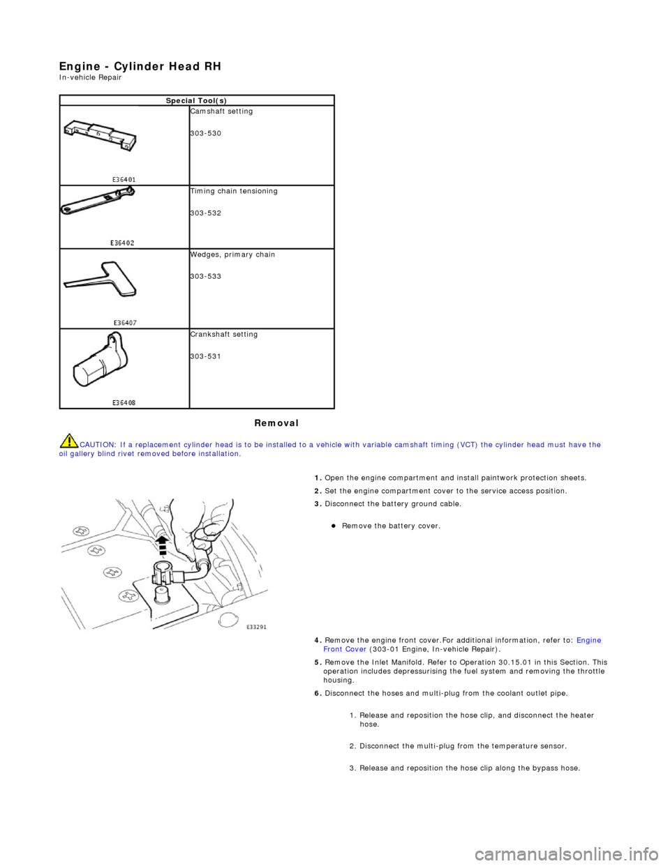
Spe
cial Tool(s)
Cams
haft setting
303-530
Ti
ming chain tensioning
303-532
Wedges, prim
ary chain
303-533
Cr
ankshaft setting
303-531
1.
Open the engine compartment and install paintwork protection sheets.
2. Set the engine compartment cover to the service access position.
3.
Disconnect the battery ground cable.
Re
move the battery cover.
4. Remove the engine front cover.For additional information, refer to: Engine
Front Cover (303-01 Engi
ne, In-vehicle Repair).
5. Remove the Inlet Manifold. Refer to Operation 30.15.01 in this Section. This operation includes depressurising the fuel system and removing the throttle
housing.
6. Disconnect the hoses and multi-plug from the coolant outlet pipe.
1. Release and reposition the hose clip, and disconnect the heater hose.
2. Disconnect the multi-plug from the temperature sensor.
3. Release and reposition the hose clip along the bypass hose.
Page 948 of 2490
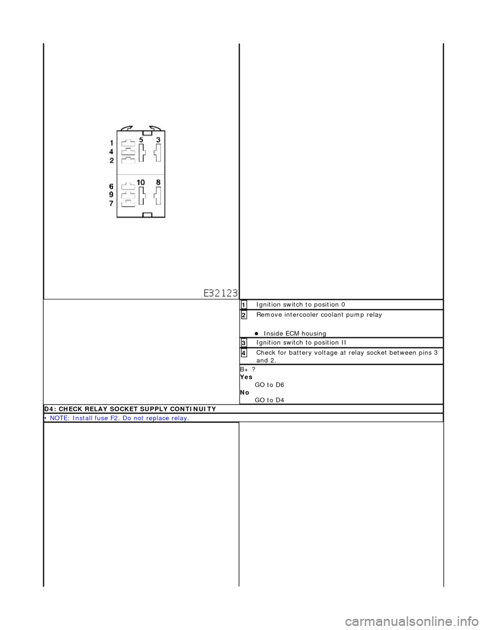
Ig
nition switch to position 0
1
R
e
move intercooler
coolant pump relay
Inside EC
M housing
2
Ignition switc
h
to position II
3
Ch
e
ck for battery voltage at relay socket between pins 3
and 2.
4
B+ ?
Yes
GO to D6
No GO to D4
D4: C H
ECK RELAY SOCKET SUPPLY CONTINUITY
•
NOTE: Install fuse F2.
Do not replace relay.
Page 1042 of 2490
Fuel Char
ging and Controls - Throttle Body
Re
mo
val and Installation
Remov
a
l
• C
A
UTIONS:
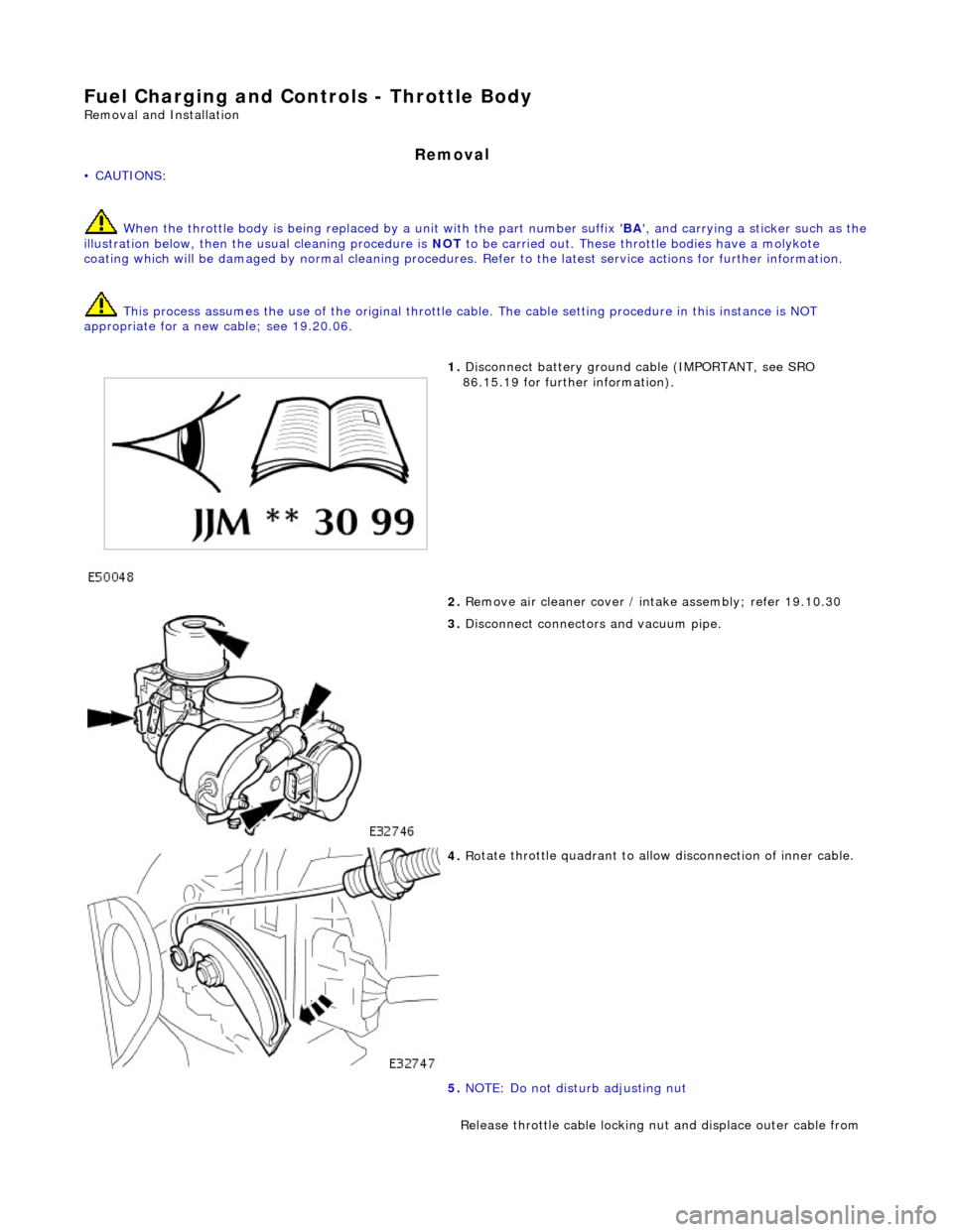
When the throttle body is being replaced by a unit with the part number suffix ' BA', and carrying a sticker such as the
illustration below, then the usual cleaning procedure is NOT to be carried out. These thro ttle bodies have a molykote
coating which will be damaged by normal cleaning procedures. Refer to the latest service action s for further information.
This process assumes the use of the original throttle ca ble. The cable setting procedure in this instance is NOT
appropriate for a new cable; see 19.20.06.
1. Disc onne
ct battery ground cable (IMPORTANT, see SRO
86.15.19 for further information).
2. Remove air cleaner cover / in take assembly; refer 19.10.30
3. Disc
onnect connectors and vacuum pipe.
4. Ro
tate throttle quadrant to allow disconnection of inner cable.
5. NOTE: Do not disturb adjusting nut
Release throttle cable locking nut and displace outer cable from
Page 1163 of 2490
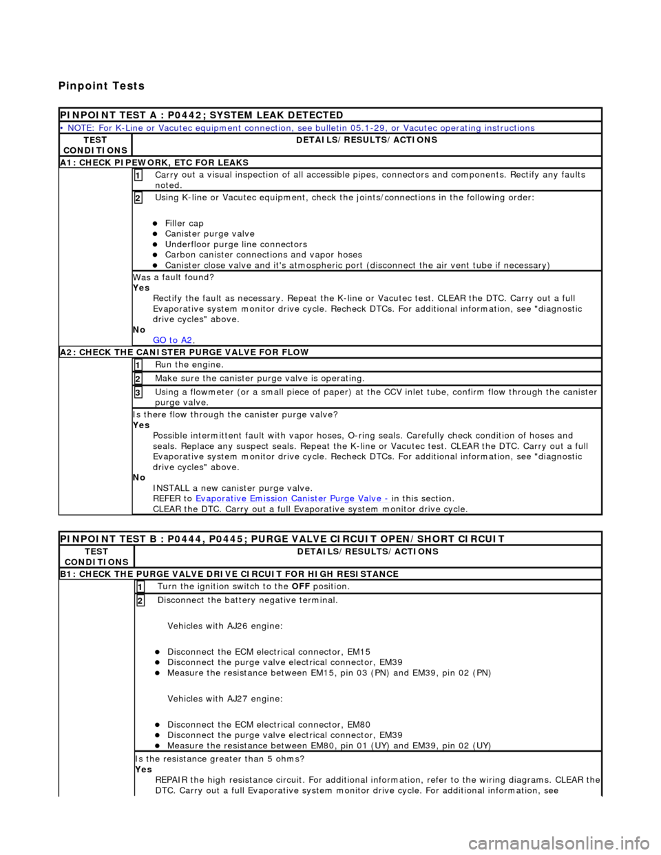
Pinpoint Tests
P
INPOINT TEST A : P0442; SYSTEM LEAK DETECTED
•
NOTE: For K-Line or Vacutec equipment connection, see bulletin 05.1-29, or Vacutec operating instructions
TE
ST
CONDITIONS
D
ETAILS/RESULTS/ACTIONS
A
1: CHECK PIPEWORK, ETC FOR LEAKS
Carr
y out a visual inspection of all accessible pipes, connectors and components. Rectify any faults
noted.
1
U
sing K-line or Vacutec equipment, check the
joints/connections in the following order:
Fi
ller cap
Cani
ster purge valve
Underfl
oor purge line connectors
Carbon
canister connections and vapor hoses
Cani
ster close valve and it's atmospheric port (disconnect the air vent tube if necessary)
2
Was
a fault found?
Yes Rectify the fault as necessary. Re peat the K-line or Vacutec test. CLEAR the DTC. Carry out a full
Evaporative system monitor drive cycle. Recheck DT Cs. For additional information, see "diagnostic
drive cycles" above.
No GO to A2
.
A2: CHECK
THE CA
NISTER PURGE VALVE FOR FLOW
Ru
n the engine.
1
Make sure the canister purge
valve is operating.
2
Using a flowmeter
(or a small piece
of paper) at the CCV inlet tube, confirm flow through the canister
purge valve.
3
Is th
ere flow through the canister purge valve?
Yes Possible intermittent faul t with vapor hoses, O-ring seals. Carefully check condition of hoses and
seals. Replace any suspect seals. Repeat the K-line or Vacutec test. CLEAR the DTC. Carry out a full
Evaporative system monitor drive cycle. Recheck DT Cs. For additional information, see "diagnostic
drive cycles" above.
No INSTALL a new canister purge valve.
REFER to Evaporative Emission Canister Purge Valve
- in t
his section.
CLEAR the DTC. Carry out a full Evap orative system monitor drive cycle.
P
INPOINT TEST B : P0444, P0445; PURGE VALVE CIRCUIT OPEN/SHORT CIRCUIT
TE
ST
CONDITIONS
D
ETAILS/RESULTS/ACTIONS
B1: CHECK
THE PURGE VALVE DRIV
E CIRCUIT FOR HIGH RESISTANCE
Turn the ignition swi
tch to the OFF
position.
1
Di
sconnect the battery negative terminal.
Vehicles with AJ26 engine:
Disc
onnect the ECM electrical connector, EM15
Di
sconnect the purge valve electrical connector, EM39
Meas
ure the resistance between EM15,
pin 03 (PN) and EM39, pin 02 (PN)
Vehicles with AJ27 engine:
Disc
onnect the ECM electrical connector, EM80
Di
sconnect the purge valve electrical connector, EM39
Meas
ure the resistance between EM80, pin 01 (UY) and EM39, pin 02 (UY)
2
Is th
e resistance greater than 5 ohms?
Yes REPAIR the high resistance circuit. For additional information, refer to the wiring diagrams. CLEAR the
DTC. Carry out a full Evaporative system monitor drive cycle. For additional information, see
Page 1245 of 2490
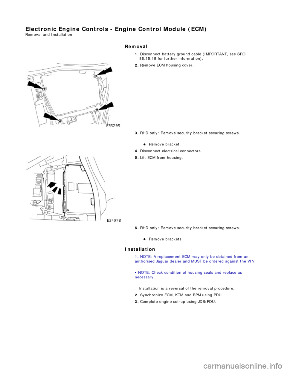
E
lectronic Engine Controls - Engine Control Module (ECM)
Re
moval and Installation
Remov
al
Installation
1.
Disc
onnect battery ground cable (IMPORTANT, see SRO
86.15.19 for further information).
2. R
emove ECM housing cover.
3. RHD only: Remove security bracket securing screws.
R
emove bracket.
4. Disconnect electrical connectors.
5. Li
ft ECM from housing.
6. RHD only: Remove security bracket securing screws.
R
emove brackets.
1. NOTE: A replacement ECM may only be obtained from an
authorised Jaguar dealer and MU ST be ordered against the VIN.
• NOTE: Check condition of ho using seals and replace as
necessary.
Installation is a reversal of the removal procedure.
2. Synchronize ECM, KTM and BPM using PDU.
3. Complete engine set- up using JDS/PDU.
Page 1358 of 2490
Installation
1.
NOTE: A replacement TCM may only be obtained from an
authorized Jaguar dealer and MU ST be ordered against the VIN.
Fitting a new TCM is the revers e of the removal procedure.
At this point ensure that the ECM is correctly located and
pushed fully rearward against the housing.
2. Connect the battery and fit the battery cover..
Reset the radio and the clock.