temperature sensor JAGUAR X308 1998 2.G Owner's Manual
[x] Cancel search | Manufacturer: JAGUAR, Model Year: 1998, Model line: X308, Model: JAGUAR X308 1998 2.GPages: 2490, PDF Size: 69.81 MB
Page 930 of 2490
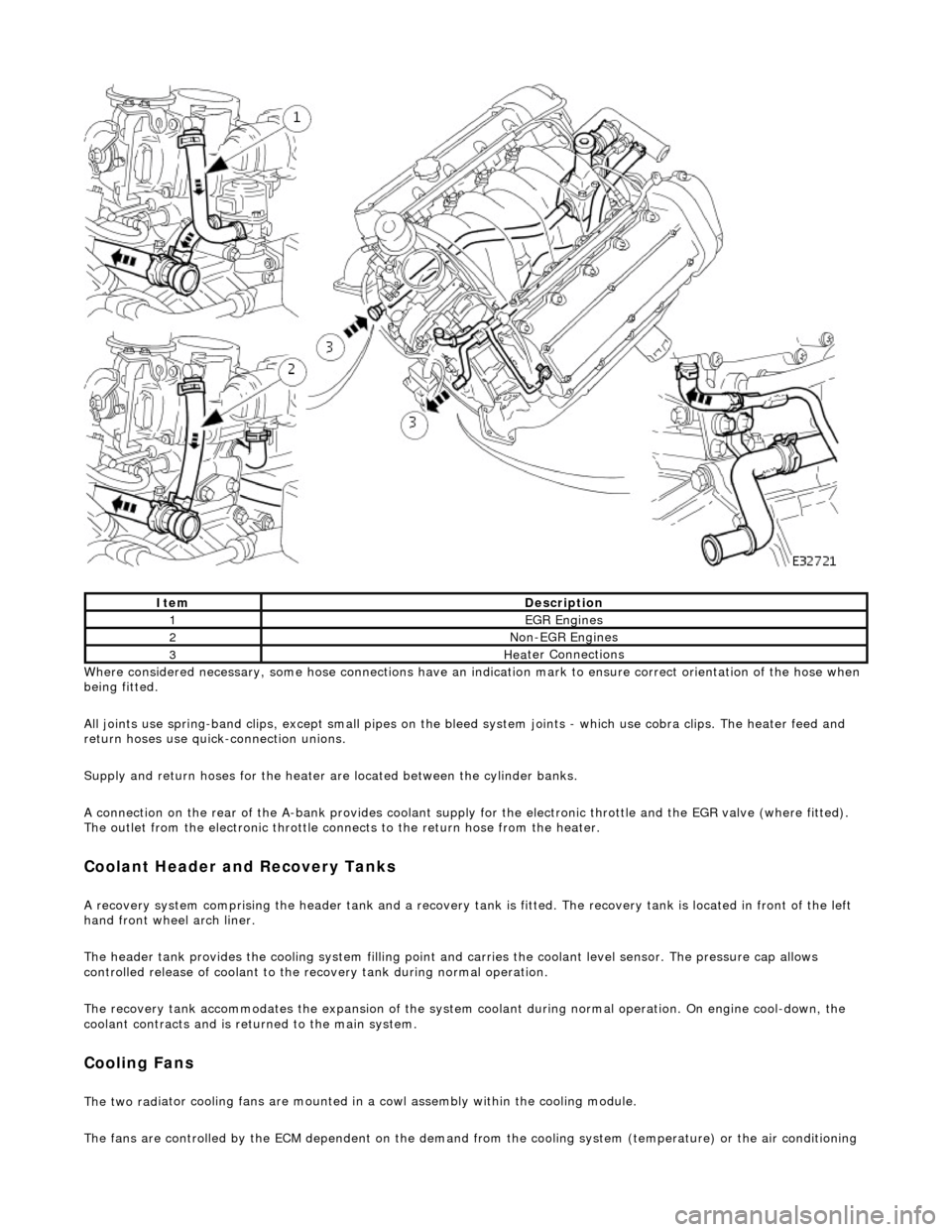
Whe r
e considered necessary, some hose conn
ections have an indication mark to ensure correct orientation of the hose when
being fitted.
All joints use spring-band clips, except small pipes on the bleed system joints - which use cobra clips. The heater feed and
return hoses use quick-connection unions.
Supply and return hoses for the heater are located between the cylinder banks.
A connection on the rear of the A-bank provides coolant supply for the electronic throttle and the EGR valve (where fitted).
The outlet from the electronic throttle connects to the return hose from the heater.
Cool
ant Header and Recovery Tanks
A recovery system comp
rising the header tank
and a recovery tank is fitted. The recove ry tank is located in front of the left
hand front wheel arch liner.
The header tank provides the cooling system filling point and carries the coolant level sensor. The pressure cap allows
controlled release of coolant to the re covery tank during normal operation.
The recovery tank accommodates the expansion of the system coolant during normal operation. On engine cool-down, the
coolant contracts and is returned to the main system.
Coo lin
g Fans
The two
rad
iator cooling fans are mounted in
a cowl assembly within the cooling module.
The fans are controlled by the ECM dependent on the demand fr om the cooling system (temperature) or the air conditioning
ItemDescrip
tion
1EGR
E
ngines
2Non
-
EGR Engines
3Hea
ter Connections
Page 931 of 2490
s
ystem (pressure).
Outputs from the ECM control the radiator fans control module, located behind the left hand side of the bumper, to operate
the fans in the series mode (slow), paralle l mode (Fast) or Off modes. Hysteresis in the temperature and pressure switching
values prevents 'hun ting' between modes.
Under hot operating conditions, the fans may continue to operat e for some time after the engine has been switched off, but
will stop automatically when the coolant te mperature has been sufficiently reduced.
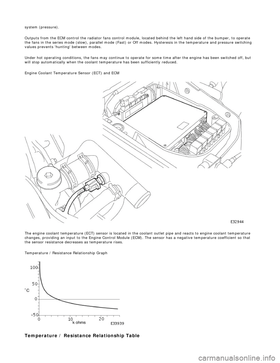
Engine Coolant Temperature Sensor (ECT) and ECM
The engine coolant temperature (ECT) sensor is located in the coolant outlet pipe and reacts to engine coolant temperature
changes, providing an input to the Engine Control Module (ECM). The sensor has a negative te mperature coefficient so that
the sensor resistance decrea ses as temperature rises.
Temperature / Resistance Relationship Graph
T
emperature / Resistance
Relationship Table
Page 932 of 2490
Engi
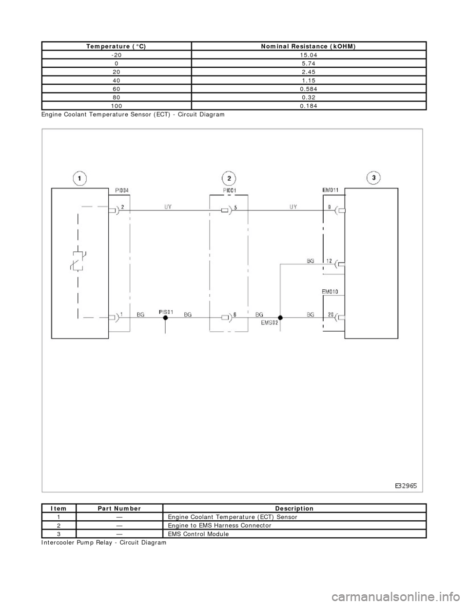
ne Coolant Temperature Sensor (ECT) - Circuit Diagram
Intercooler Pump Relay - Circuit Diagram
T emper
ature (°C)
No
mi
nal Resistance (kOHM)
-2
015 .0
4
05.7
4
202.45
401.15
600.
584
800.3
2
1000.
184
ItemPar
t
Number
De
scrip
tion
1—Eng
i
ne Coolant Temperature (ECT) Sensor
2—Eng
i
ne to EMS Harness Connector
3—EMS Con
trol Modu
le
Page 934 of 2490
Engine Cooling - Engine Cooling
Diagn
osis and Testing
Related Faults / Codes
Adaptive
Fue
ling
Sym
p
tom Chart
Sy
m
ptom Chart
S
p
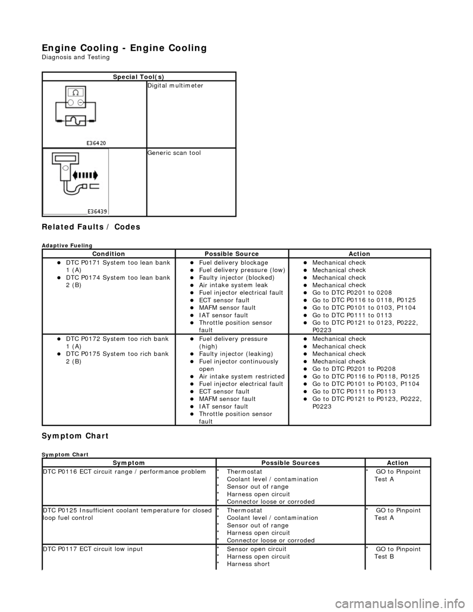
ecial Tool(s)
D
i
gital multimeter
Generi
c scan tool
Conditi
on
Possib
l
e Source
Acti
o
n
D
T
C P0171 System too lean bank
1 (A)
D T
C P0174 System too lean bank
2 (B)
Fuel delivery blockage Fu
el delivery pressure (low)
F
a
ulty injector (blocked)
Ai
r i
ntake system leak
F
u
el injector electrical fault
ECT sensor
faul
t
MAFM sensor fault IAT se
nsor fault
Thro
tt
le position sensor
fault
Mec hanica
l check
Mec
hanica
l check
Mec
hanica
l check
Mec
hanica
l check
Go t
o DTC P020
1 to 0208
Go t
o
DTC P0116 to 0118, P0125
Go t
o
DTC P0101 to 0103, P1104
Go t
o DTC P011
1 to 0113
Go t
o
DTC P0121 to 0123, P0222,
P0223
D T
C P0172 System too rich bank
1 (A)
D T
C P0175 System too rich bank
2 (B)
F u
el delivery pressure
(high)
F a
ulty injector (leaking)
F
u
el injector continuously
open
Ai r i
ntake system restricted
Fu
el injector electrical fault
ECT sensor
faul
t
MAFM sensor fault IAT sensor fault
Thrott
le position sensor
fault
Mec hanica
l check
Mec
hanica
l check
Mec
hanica
l check
Mec
hanica
l check
Go t
o DTC P020
1 to P0208
Go t
o
DTC P0116 to P0118, P0125
Go t
o
DTC P0101 to P0103, P1104
Go t
o DTC P011
1 to P0113
Go t
o
DTC P0121 to P0123, P0222,
P0223
Sy m
ptom
Possib
l
e Sources
Acti
o
n
D
T
C P0116 ECT circuit range / performance problem
Thermostat
Coo
l
ant level / contamination
Sensor out of range
Harness open circuit
Connector loose or corroded
*
*
*
*
*
GO to Pinpoint
Test A
*
D
T
C P0125 Insufficient coolant temperature for closed
loop fuel control
Thermostat
Coo l
ant level / contamination
Sensor out of range
Harness open circuit
Connector loose or corroded
*
*
*
*
*
GO to Pinpoint
Test A
*
D
T
C P0117 ECT circuit low input
Sensor o
p
en circuit
Harness open circuit
Harness short
*
*
*
GO to Pinpoint
Test B
*
Page 935 of 2490
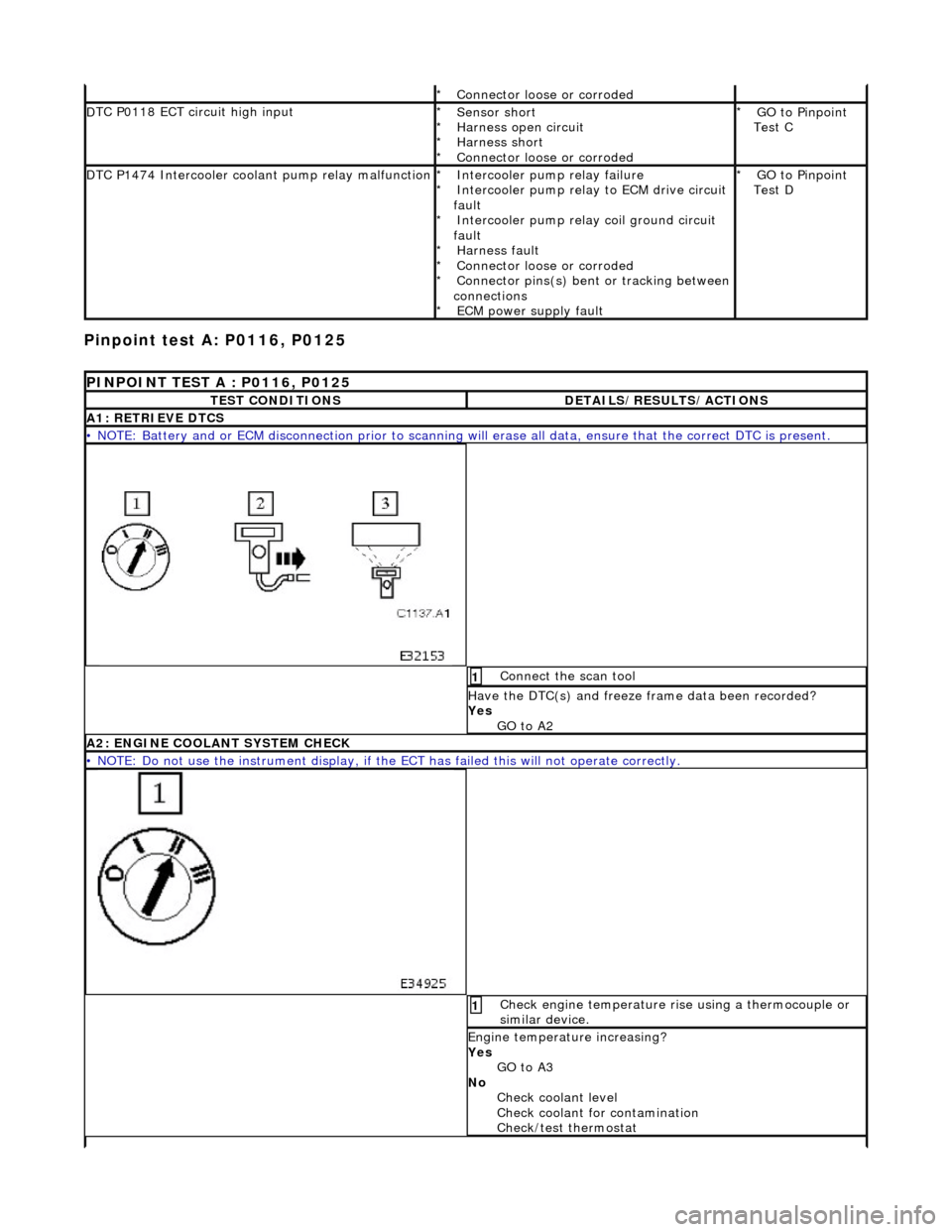
Pinpoint test
A: P0116, P0125
Connector
loose or corroded
*
D
TC P0118 ECT circuit high input
Sensor short
Harness open circui
t
Harness short
Connector loose or corroded
*
*
*
*
GO to Pinpoint
Test C
*
D
TC P1474 Intercooler coolant pump relay malfunction
Intercooler pump relay
failure
Intercooler pump relay to ECM drive circuit
fault Intercooler pump relay coil ground circuit
fault Harness fault
Connector loose or corroded
Connector pins(s) bent or tracking between
connections ECM power supply fault
*
*
*
*
*
*
*
GO to Pinpoint
Test D
*
P
INPOINT TEST A : P0116, P0125
T
EST CONDITIONS
D
ETAILS/RESULTS/ACTIONS
A1
: RETRIEVE DTCS
•
NOTE: Battery and or ECM disconnection prior to scanning wi
ll erase all data, ensure that the correct DTC is present.
Conne
ct the scan tool
1
Have the DTC(s) and fr
eeze
frame data been recorded?
Yes GO to A2
A2: ENGINE
COOLANT SYSTEM CHECK
•
NOTE: Do not use the instrument display, if th
e ECT has failed this will not operate correctly.
Chec
k engine temperature rise using a thermocouple or
similar device.
1
Engine
temperature increasing?
Yes GO to A3
No Check coolant level
Check coolant for contamination
Check/test thermostat
Page 936 of 2490

A3: CHECK ECT SE
NSOR RANGE
All
o
w the engine to achieve any noted temperature within
the specified range, refer to temperature / resistance
relationship table or graph
1
I g
nition switch to position 0
2
D
i
sconnect PI004
Re
ar
of top hose
3
Meas
ure t
he resistance between sensor pins 1 and 2.
4
Tem
p
erature / resistance relationship OK?
Yes GO to A4
No Remove sensor and check temperature / resistance
relationship for 3 different temperatures. Renew as
required and test the syst em for normal operation.
A4: CHECK
HARNESS
CONTINUITY
Page 965 of 2490

Engine Cooling - Coolant Outlet Pipe
Re
moval and Installation
Remov
al
Installation
1.
O
pen the engine compartment and fit paintwork protection
sheets.
2. Drain the radiator. Refer to Ge neral Procedures. Retain the
coolant drain tray in position to catch any spillage when
removing the outlet pipe.
3. Di
sconnect the hoses and multi-plug from the coolant outlet
pipe.
1. Release and reposition th e hose clip, and disconnect
the top hose.
2. Release and reposition th e hose clip, and disconnect
the heater hose.
3. Disconnect the multi-plug from the temperature sensor and unscrew the sens or from the outlet pipe.
4. Release and reposition the hose clip along the bypass
hose.
4. R
emove the coolant outlet pipe.
1. Remove the four bolts which secure the outlet pipe.
2. Remove the outlet pipe from the bypass hose and
from the cylinder heads.
5. Remove and discard the sealing rings from the outlet pipe
grooves.
1. Installation is the reverse of the remova l procedure. Use new
sealing rings on the coolant outlet pipe.
2. Tighten the coolant outlet pipe bolts to 10-14 Nm If replacing
the coolant temperature sensor, tighten to 15-19 Nm.
3. Refill the cooling system as de scribed in General Procedures.
Page 966 of 2490

Engine Cooling - Coolant Outlet Pipe
Remo
val and Installation
Remov
a
l
1.
Op
en the engine compartment and fit paintwork protection
sheets.
2. Drain the radiator. Refer to Ge neral Procedures. Retain the
coolant drain tray in position to catch any spillage when
removing the outlet pipe.
3. Disc onne
ct the top hose and br
eather pipe from the coolant
outlet pipe.
1. Release and reposition th e hose clip, and disconnect
the top hose.
2. Release and disconnect the breather pipe quick fit connector.
3. Disconnect the multi-plug from the temperature sensor and unscrew the sens or from the outlet pipe.
4. Release and reposition the hose clip along the bypass
hose.
4. Disc
onnect the bottom hose
from the thermostat housing.
1. Release and reposition th e hose clip along the hose.
2. Disconnect the bottom hose.
5. Disc
onnect the coolant outlet pipe from the cylinder heads.
1. Remove the four bolts which secure the outlet pipe.
2. Remove the outlet pipe from the bypass hose and
from the cylinder heads (still connected to the
heater hose).
6. Release and reposition the clip which secures the heater hose
to the outlet pipe and disconnect the hose. Remove the outlet
pipe.
7. Remove the thermostat from the outlet pipe.
1. Remove the three bolts which secure the thermostat cover to the outlet pipe.
2. Remove the thermostat cover, the thermostat and
the seal from the outlet pipe. Discard the seal.
Page 967 of 2490

I
nstallation
8.
Remove an
d discard the sealing
rings from the outlet pipe
grooves.
1. Installation is th e reverse of the re moval procedure.
Use new
sealing rings on th
e coolant outlet pipe and
thermostat housing.
The t
hermostat ball valve must
locate in the recess in the
cover.
2. Tighten the coolant outlet pipe bolts to 8-12 Nm. If replacing
the coolant temperature sensor, tighten to 15-19 Nm.
3. Refill the cooling system as de scribed in General Procedures.
Page 1021 of 2490
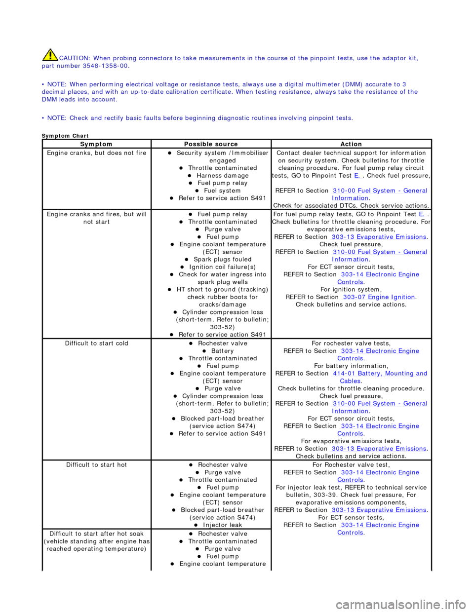
CAUTI
ON: When probing connectors to take
measurements in the course of the pinpoint tests, use the adaptor kit,
part number 3548-1358-00.
• NOTE: When performing electrical voltag e or resistance tests, always use a digital multimeter (DMM) accurate to 3
decimal places, and with an up-t o-date calibration certificate. When testing resistance, always take the resistance of the
DMM leads into account.
• NOTE: Check and rectify basic faults before beginning diagnostic ro utines involving pinpoint tests.
Sy
mptom Chart
Sy
mptom
Possib
le source
Acti
on
Engine
cranks, but does not fire
Secu
rity system /Immobiliser
engaged
Thr
ottle contaminated
Harness damage
F
uel pump relay
Fue
l system
R
efer to service action S491
Contact dealer techn
ical
support for information
on security system. Chec k bulletins for throttle
cleaning procedure. For fuel pump relay circuit
tests, GO to Pinpoint Test E.
.
Check fuel pressure,
REFER to Section 310
-00
Fuel System
- Gen
eral
Informati
on
.
Chec
k for associated DTCs
. Check service actions.
Engine
cranks and fires, but will
not start
F
uel pump relay
Thr
ottle contaminated
Purge
valve
Fue
l pump
Engine coolan
t temperature
(ECT) sensor
Spark plugs
fouled
Ignition coil
failure(s)
Check f
or water ingress into
spark plug wells
HT sho
rt to ground (tracking)
check rubber boots for cracks/damage
Cyl
inder compression loss
(short-term. Refer to bulletin;
303-52)
R
efer to service action S491
F
or fuel pump relay tests,
GO to Pinpoint Test E.
.
Check bull
etins for throttle cleaning procedure. For
evaporative emissions tests,
REFER to Section 303
-1
3 Evaporative Emissions
. Chec
k fuel pressure,
REFER to Section 310
-00
Fuel System
- Ge
neral
Informati
on
.
F
or ECT sensor circuit tests,
REFER to Section 303
-14 Elec
tronic Engine
Controls.
For ign
ition system,
REFER to Section 303
-07
Engine Ignition
.
Check bulletins an d service
actions.
D
ifficult to start cold
Roc
hester valve
Batt
ery
Thr
ottle contaminated
Fue
l pump
Engine coolan
t temperature
(ECT) sensor
Purge
valve
Cyl
inder compression loss
(short-term. Refer to bulletin;
303-52)
Blocked part-load breather (
service action S474)
R
efer to service action S491
F
or rochester valve tests,
REFER to Section 303
-14 Elec
tronic Engine
Controls.
F
or battery information,
REFER to Section 414
-0
1 Battery, Mounting and
Cables.
Check bull
etins for throttle cleaning procedure.
Check fuel pressure,
REFER to Section 310
-00
Fuel System
- Ge
neral
Informati
on
.
F
or ECT sensor circuit tests,
REFER to Section 303
-14 Elec
tronic Engine
Controls.
For evaporat
ive emissions tests,
REFER to Section 303
-1
3 Evaporative Emissions
. Check bulletins an
d
service actions.
D
ifficult to start hot
Roc
hester valve
Purge
valve
Thr
ottle contaminated
Fue
l pump
Engine coolan
t temperature
(ECT) sensor
Blocked part-load breather (
service action S474)
Injec
tor leak
F
or Rochester
valve test,
REFER to Section 303
-14 Elec
tronic Engine
Controls.
Fo
r injector leak test, REFER to technical service
bulletin, 303-39. Check fuel pressure, For evaporative emissions components,
REFER to Section 303
-1
3 Evaporative Emissions
. F
or ECT sensor tests,
REFER to Section 303
-14 Elec
tronic Engine
Controls. D
ifficult to start after hot soak
(vehicle standing after engine has
reached operating temperature)
Roc
hester valve
Thr
ottle contaminated
Purge
valve
Fue
l pump
Engine coolan
t temperature