auxiliary battery JAGUAR X308 1998 2.G Workshop Manual
[x] Cancel search | Manufacturer: JAGUAR, Model Year: 1998, Model line: X308, Model: JAGUAR X308 1998 2.GPages: 2490, PDF Size: 69.81 MB
Page 26 of 2490

Side Turn Signal Lamp (86.41.41)
Side Turn Signal Lamp Bulb (86. 41.42)
417‐02
:
Interior Lighting
Specification
Description and Operation
Interior Lighting
Diagnosis and Testing
Interior Lighting
Removal and Installation
Door Courtesy Lamp (86.40.38)
Door Courtesy Lamp Bulb (86.40.47)
Door Courtesy Lamp Lens (86.40.35)
Glove Co
mpartment Lamp (86.45.08)
Luggage Compartment Lamp (86.45.16)
Vanity Mirror Lamp (76.10.50)
417‐04: Daytime Running Lamps (DRL)
Description and Operation
Daytime Running Lamps (DRL)
Diagnosis and Testing
Daytime Running Lamps (DRL)
418: Electrical Distribution
418‐00: Module Communications Network
Description and Operation
Communications Ne
twork
Removal
and Installation
Battery
Junction Box (BJB) (86.70.69)
Central
Junction Box (CJB) (86.70.72)
Front
Auxiliary Junction Box (86.70.73)
Rear
Auxiliary Junction Box (86.70.74)
418 ‐02: Wiring Harnesses
Description and Operati
on
Wiring Harness
General Procedures
Wiring Harness Repair
Page 1835 of 2490

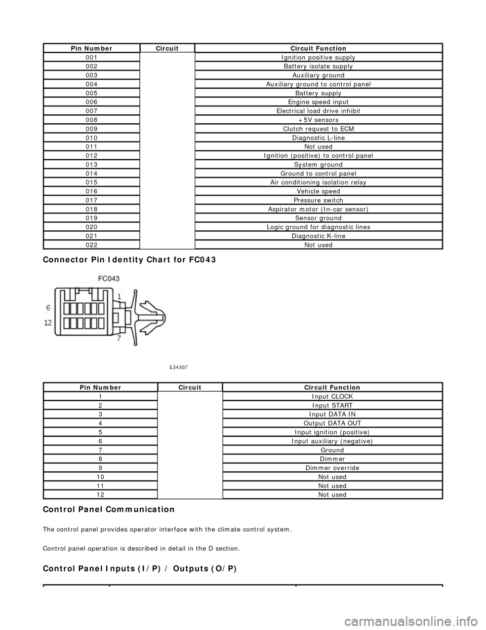
Connector Pin Identity Chart for FC043
Control Panel Communication
The control panel provides operator interface with the climate control system.
Control panel operation is described in detail in the D section.
Control Panel Inputs (I/P) / Outputs (O/P)
Pin NumberCircuitCircuit Function
001Ignition positive supply
002Battery isolate supply
003Auxiliary ground
004Auxiliary ground to control panel
005Battery supply
006Engine speed input
007Electrical load drive inhibit
008+5V sensors
009Clutch request to ECM
010Diagnostic L-line
011Not used
012Ignition (positive) to control panel
013System ground
014Ground to control panel
015Air conditioning isolation relay
016Vehicle speed
017Pressure switch
018Aspirator motor (In-car sensor)
019Sensor ground
020Logic ground for diagnostic lines
021Diagnostic K-line
022Not used
Pin NumberCircuitCircuit Function
1Input CLOCK
2Input START
3Input DATA IN
4Output DATA OUT
5Input ignition (positive)
6Input auxiliary (negative)
7Ground
8Dimmer
9Dimmer override
10Not used
11Not used
12Not used
Page 1985 of 2490

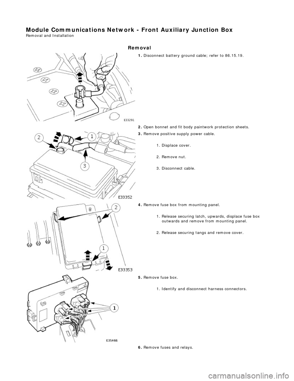
Module Communications Network - Front Auxiliary Junction Box
Removal and Installation
Removal
1. Disconnect battery ground cable; refer to 86.15.19.
2. Open bonnet and fit body pa intwork protection sheets.
3. Remove positive supply power cable.
1. Displace cover.
2. Remove nut.
3. Disconnect cable.
4. Remove fuse box fro m mounting panel.
1. Release securing latch, upwards, displace fuse box
outwards and remove from mounting panel.
2. Release securing tangs and remove cover.
5. Remove fuse box.
1. Identify and disconne ct harness connectors.
6. Remove fuses and relays.
Page 1987 of 2490

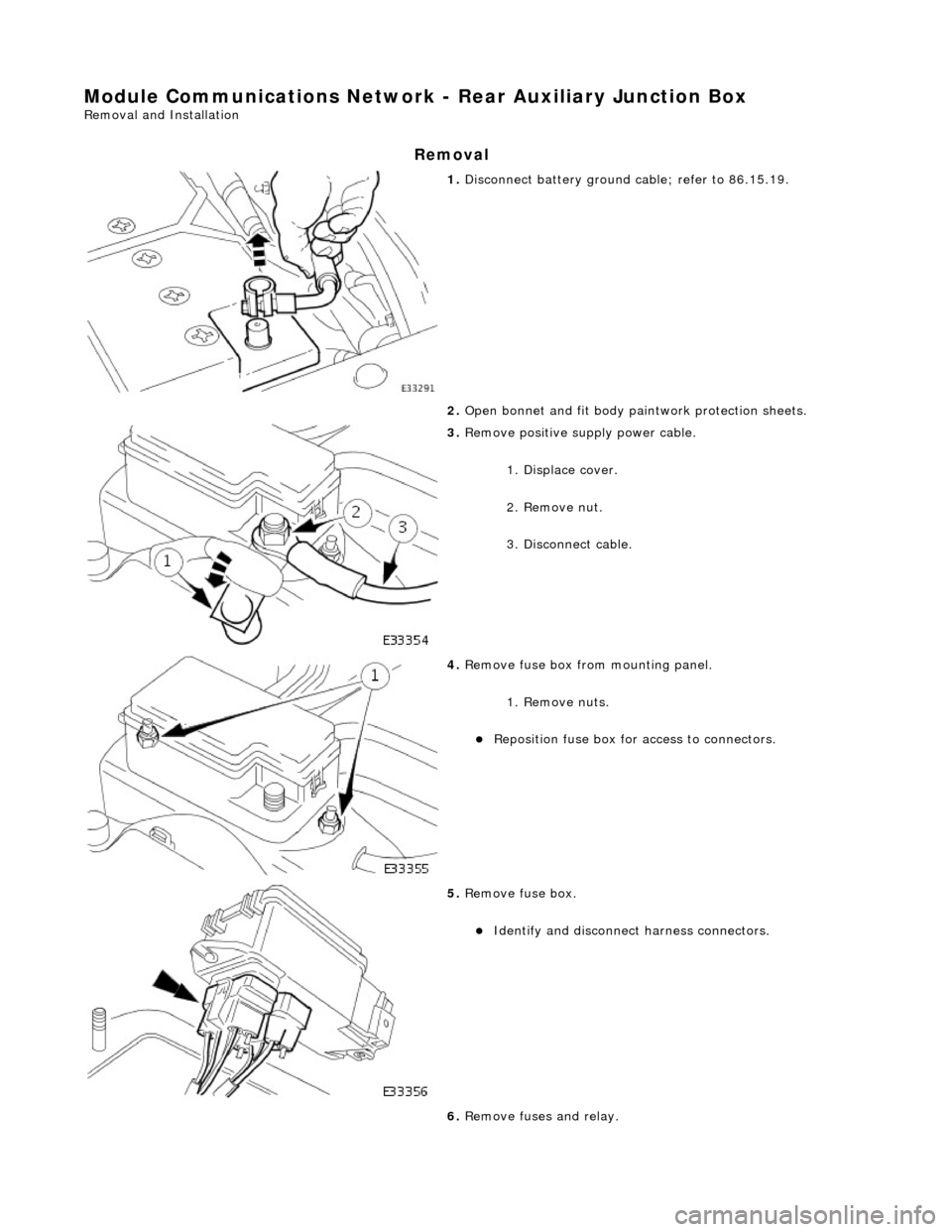
Module Communications Network - Rear Auxiliary Junction Box
Removal and Installation
Removal
1. Disconnect battery ground cable; refer to 86.15.19.
2. Open bonnet and fit body pa intwork protection sheets.
3. Remove positive supply power cable.
1. Displace cover.
2. Remove nut.
3. Disconnect cable.
4. Remove fuse box fro m mounting panel.
1. Remove nuts.
Reposition fuse box for access to connectors.
5. Remove fuse box.
Identify and disconnect harness connectors.
6. Remove fuses and relay.