temperature sensor JAGUAR X308 1998 2.G Repair Manual
[x] Cancel search | Manufacturer: JAGUAR, Model Year: 1998, Model line: X308, Model: JAGUAR X308 1998 2.GPages: 2490, PDF Size: 69.81 MB
Page 1209 of 2490

Is th
e voltage greater than 3 volts?
Yes REPAIR the short circuit. For addi tional information, refer to the wiring diagrams. CLEAR the DTC.
TEST the system for normal operation.
No GO to B3
.
B3: CHECK
THE IAT SENSOR SENS
E CIRCUIT FOR SHORT TO GROUND
Turn the ignition swi
tch to the OFF
position.
1
Meas
ure the resistance between PI35, pin 03 (UP) and GROUND.
2
Is
the resistance less than 10,000 ohms?
Yes
REPAIR the short circuit. For addi tional information, refer to the wiring diagrams. CLEAR the DTC.
TEST the system for normal operation.
No INSTALL a new MAF sensor.
REFER to Mass Air Flow (MAF) Sensor
in this section.
CLEAR the DTC. TEST the system for normal operation.
PI
NPOINT TEST C : DTC P0116, P0117, P0118
; ENGINE COOLANT TEMPERATURE (ECT) SENSOR
RANGE/PERFORMANCE, HIGH/LOW VOLTAGE
•
NOTE: Before commencing this
test, check the coolant level and condition, check the operation of the thermostat, rectify
as necessary.
TE
ST
CONDITIONS
D
ETAILS/RESULTS/ACTIONS
C1: CHECK THE ECT SEN
SOR SENS
E CIRCUIT FOR HIGH RESISTANCE
Di
sconnect the battery negative terminal.
1
D
isconnect the ECM electrical connector, EM11.
2
D
isconnect the ECT sensor electrical connector, PI04.
3
Meas
ure the resistance between EM11, pin 09 (UY) and PI04, pin 02 (UY).
4
Is th
e resistance greater than 5 ohms?
Yes
REPAIR the high resistance circui t. For additional information, refer to the wiring diagrams. CLEAR
the DTC. TEST the system for normal operation.
No GO to C2
.
C2: CHECK THE ECT SEN
SOR SENSE CI
RCUIT FOR SHORT TO HIGH VOLTAGE
R
econnect the battery negative terminal.
1
Turn the ignition swi
tch to the ON
position.
2
Meas
ure the voltage between PI04, pin 02 (UY) and GROUND.
3
Is th
e voltage greater than 3 volts?
Yes REPAIR the short circuit. For addi tional information, refer to the wiring diagrams. CLEAR the DTC.
TEST the system for normal operation.
No GO to C3
.
C3: CHECK THE ECT SEN
SOR SENSE CIRCUIT FOR SHORT TO GROUND
Turn the ignition swi
tch to the OFF
position.
1
Meas
ure the resistance between PI04, pin 02 (UY) and GROUND.
2
Is
the resistance less than 10,000 ohms?
Yes REPAIR the short circuit. For addi tional information, refer to the wiring diagrams. CLEAR the DTC.
TEST the system for normal operation.
No INSTALL a new ECT sensor. REFER to Section 303
-0
3A Engine Cooling
/
30
3
-0
3B Supercharger
Coo
ling
. CLEA
R the DTC. TEST the sy
stem for normal operation.
P
INPOINT TEST D : DTC P0121, P0122,
P0123; THROTTLE POSITION (TP) SENSOR
RANGE/PERFORMANCE, HIGH/LOW VOLTAGE
TE
ST
CONDITIONS
D
ETAILS/RESULTS/ACTIONS
D1: CHECK
THE TP SENSOR SENS
E CIRCUIT FOR HIGH RESISTANCE
Di
sconnect the battery negative terminal.
1
Page 1219 of 2490
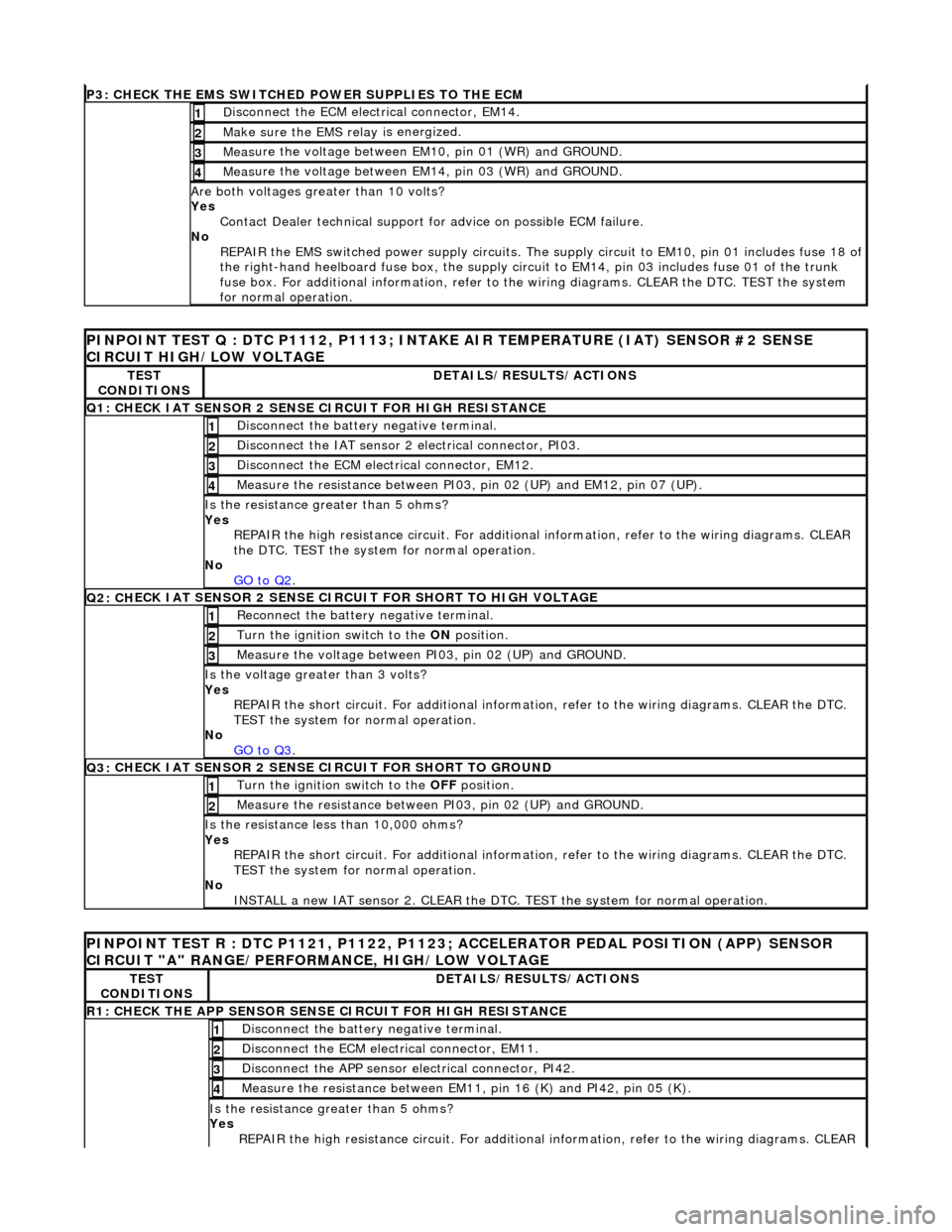
P3: CHECK
THE EMS SWITCHED
POWER SUPPLIES TO THE ECM
D
isconnect the ECM electrical connector, EM14.
1
Make sure the EMS re
lay i
s energized.
2
Meas
ure the voltage between EM10, pin 01 (WR) and GROUND.
3
Meas
ure the voltage between EM14, pin 03 (WR) and GROUND.
4
Are both
voltages greater than 10 volts?
Yes Contact Dealer technical support for advice on possible ECM failure.
No REPAIR the EMS switched power supply circuits. The su pply circuit to EM10, pin 01 includes fuse 18 of
the right-hand heelboard fuse box, the supply circuit to EM14, pin 03 includes fuse 01 of the trunk
fuse box. For additional information, refer to th e wiring diagrams. CLEAR the DTC. TEST the system
for normal operation.
PI
NPOINT TEST Q : DTC P1112, P1113; INTAKE
AIR TEMPERATURE (IAT) SENSOR #2 SENSE
CIRCUIT HIGH/LOW VOLTAGE
TE
ST
CONDITIONS
D
ETAILS/RESULTS/ACTIONS
Q1:
CHECK IAT SENSOR 2 SENSE CIRCUIT FOR HIGH RESISTANCE
Di
sconnect the battery negative terminal.
1
Di
sconnect the IAT sensor 2 electrical connector, PI03.
2
D
isconnect the ECM electrical connector, EM12.
3
Me
asure the resistance between PI03, pin 02 (UP) and EM12, pin 07 (UP).
4
Is th
e resistance greater than 5 ohms?
Yes REPAIR the high resistance circui t. For additional information, refer to the wiring diagrams. CLEAR
the DTC. TEST the system for normal operation.
No GO to Q2
.
Q2: CH
ECK IAT SENSOR 2 SENSE CIRC
UIT FOR SHORT TO HIGH VOLTAGE
R
econnect the battery negative terminal.
1
Turn the ignition swi
tch to the ON
position.
2
Measure the
voltage between PI
03, pin 02 (UP) and GROUND.
3
Is th
e voltage greater than 3 volts?
Yes REPAIR the short circuit. For addi tional information, refer to the wiring diagrams. CLEAR the DTC.
TEST the system for normal operation.
No GO to Q3
.
Q3:
CHECK IAT SENSOR 2 SENSE CIRCUIT FOR SHORT TO GROUND
Turn the ignition swi
tch to the OFF
position.
1
Meas
ure the resistance between PI03, pin 02 (UP) and GROUND.
2
Is
the resistance less than 10,000 ohms?
Yes REPAIR the short circuit. For addi tional information, refer to the wiring diagrams. CLEAR the DTC.
TEST the system for normal operation.
No INSTALL a new IAT sensor 2. CLEAR the DTC. TEST the system for normal operation.
P
INPOINT TEST R : DTC P1121, P1122, P1123;
ACCELERATOR PEDAL POSITION (APP) SENSOR
CIRCUIT "A" RANGE/PERFORMANCE, HIGH/LOW VOLTAGE
TE
ST
CONDITIONS
D
ETAILS/RESULTS/ACTIONS
R1: CHECK THE APP
SENSOR SENSE CIRCUIT FOR HIGH RESISTANCE
Di
sconnect the battery negative terminal.
1
D
isconnect the ECM electrical connector, EM11.
2
Di
sconnect the APP sensor electrical connector, PI42.
3
Meas
ure the resistance between EM11, pin 16 (K) and PI42, pin 05 (K).
4
Is th
e resistance greater than 5 ohms?
Yes REPAIR the high resistance circui t. For additional information, refer to the wiring diagrams. CLEAR
Page 1246 of 2490

El
ectronic Engine Controls - En
gine Coolant Temperature (ECT)
Sensor4.0L NA V8 - AJ 27/3.2L NA V8 - AJ26
Remo
val and Installation
Remova
l
Installation
1. Op
en the engine compartment and fit paintwork protection
sheets.
2. Re
move the engine covers.
3. WA
RNING: ENSURE THAT THE ENGINE IS COLD BEFORE
COMMENCING WORK.
Slacken the coolant reservoir ca p to relieve coolant pressure
and re-tighten.
4. Remove t
he engine coolant temperature sensor.
1. Disconnect the harness plug from the sensor.
2. Remove the sensor and sealing washer.
1. Fitting is the reverse of the removal procedure, noting that a
new sealing washer should be us ed and tighten the sensor as
specified
Page 1248 of 2490

El
ectronic Engine Controls - En
gine Coolant Temperature (ECT)
Sensor4.0L SC V8 - AJ26
Re mo
val and Installation
Remova
l
Installation
1.
Op
en the engine compartment and fit paintwork protection
sheets.
2. WA
RNING: ENSURE THAT THE ENGINE IS COLD BEFORE
COMMENCING WORK.
Slacken the coolant reservoir ca p to relieve coolant pressure
and re-tighten.
3. Remove t
he engine coolant temperature sensor.
1. Disconnect the harness plug from the sensor.
2. Remove the sensor and sealing washer.
1. Fi
tting is the reverse of the removal procedure, noting that a
new sealing washer should be us ed and tighten the sensor as
specified
2. Check and adjust the cool ant level as required.
Page 1251 of 2490

E
lectronic Engine Controls - Inta
ke Air Temperature (IAT) Sensor
Re
moval and Installation
Remov
al
Installation
1.
Di
sconnect sensor connector at
rear of bank 1 charge air
cooler.
2. Re
move sensor.
Re
move sensor using a deep socket.
Discard sealin
g washer.
1. Installation is a reversal of the removal procedure.
Page 1262 of 2490
Contains th
e hydraulic system pump.
Contains
th
e fluid temperature sensor.
The epicyclic geartrain:
Provi des fi
ve forward gears and Reverse.
Has
h
ydraulically actuated, multi-disk clutches, to select the required gear ratios.
Feature
s clutch-to-clutch operation to permit
gear shifts for uninterrupted power flow.
The electro-hydraulic control unit:
Is lo c
ated in the lower part of
the unit, within the fluid pan.
Is controlled
by the TCM (transmissio
n control module), and the manual selector valve which is cable operated.
Re
gulates the flow of fluid to the ge
artrain clutches via three solenoid-operated valv es and the manual selector
valve.
Has fi ve pressure
regulators for controll
ing fluid pressures within the system.
Is con
nected to the TCM via a 16-way connector mounted on
the left-hand side of the transmission casing. Refer to
Connector Pins Identification, Section 307-01A.
The hydraulic system pump:
Is l o
cated at the front of the transmission casing.
Is dri
v
en from the impeller hub,
pressurising the fluid whenever the engine is running.
Supplie
s fluid under pressure to the torq
ue converter, geartrain, electro-hydr aulic control unit and the lubrication
circuit.
D r
aws fluid from the fluid pa
n below the transmission casing, through a filter.
The rear extension housing:
Is bolt
ed to the rear of the transmission casing.
Provides the rear engine / transmi
ssion mo
unting point; refer to section 303-01.
Carrie
s the transmission output shaft oil seal.
Filled-for-l
i
fe Fluid System
The
transm
ission is 'filled for life' and
does not require fluid changes, except where extreme driving conditions prevail.
Routine level checking is not required and a dipstick is not pr ovided. A level / filler plug is fitted for level checking and
replenishment, following service actions; see 303-01 General Procedures.
Transmission Torque Converter
Page 1265 of 2490
Voltage is monitored at the regulators and solenoids for continuity and shorts. For example, when a solenoid is ON the
voltage on the TCM side should be ground , when OFF the voltage should be +12.
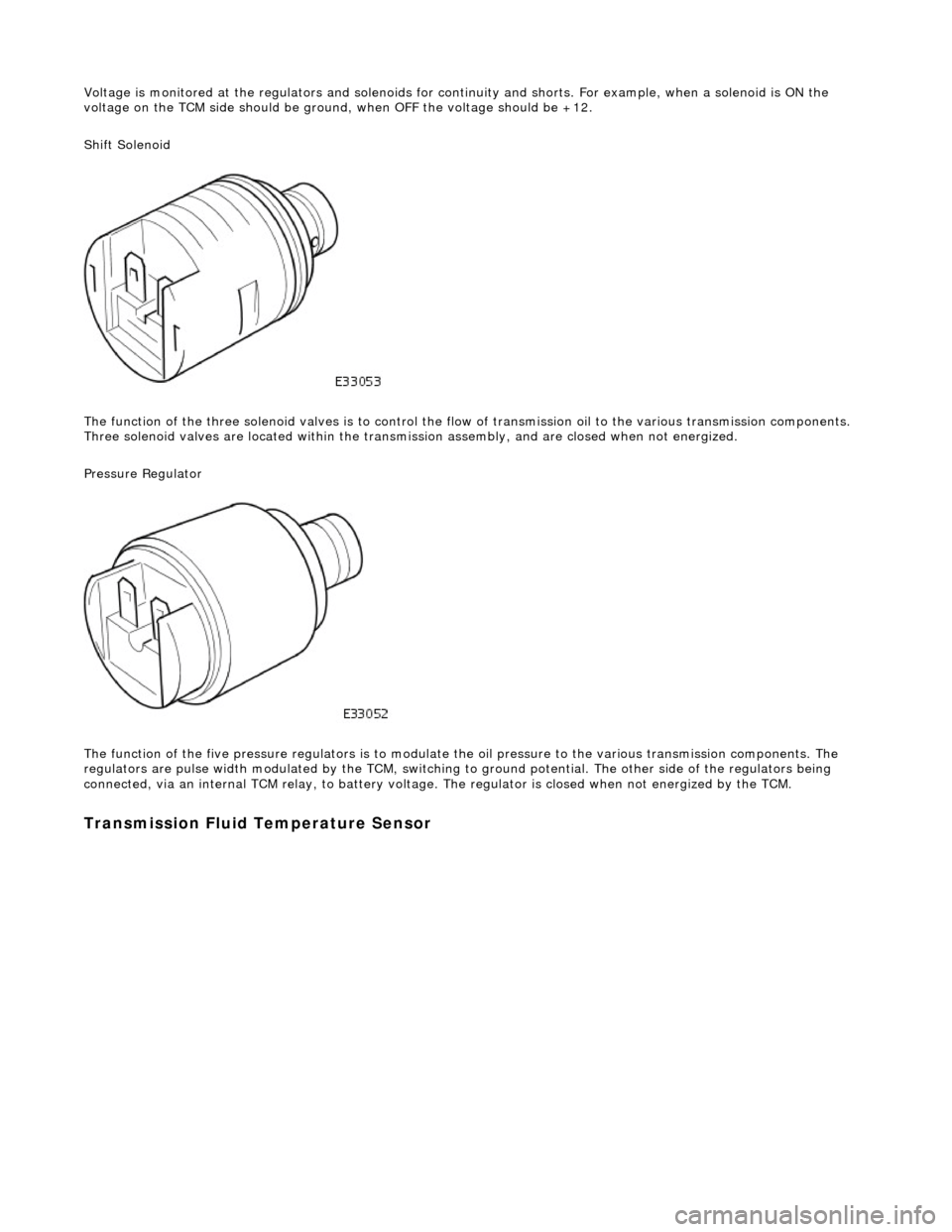
Shift Solenoid
The function of the three soleno id valves is to control the flow of transmissi on oil to the various transmission components.
Three solenoid valves are located wi thin the transmission assembly, and are closed when not energized.
Pressure Regulator
The function of the five pressu re regulators is to modulate the oil pressure to the various transmission components. The
regulators are pulse width modulated by the TCM, switching to ground potential. The other side of the regulators being
connected, via an internal TCM relay, to battery voltage. The regulator is closed when not energized by the TCM.
Transmission Fluid Temperature Sensor
Page 1266 of 2490

Operation
The transmission fluid temperature sensor is integrated into the internal harness within the fluid pan.
It should be noted that this component is not serviceable, ne cessitating the renewal of the internal harness should a fault
occur.
Following engine start-up, if the fluid temperature is < 20 °C and does not increase by 10 °C after 180 seconds, a failure
judgement is made. A similar judgement is made should the temperature change by more than 5 °C in <100 milliseconds.
The MIL is illuminated if the failure judgement is made on two successive trips.
Sensor output is continuously monitored for out of range values. If a sustained high, or low inpu t is sensed, indicating a
harness or connector fault, a failure judgement is made.
Location of Sensor Within The Harness
Temperature / Resistance Relationship Chart
Page 1267 of 2490
Transmission Speed Sensors (Gear Shift Control)
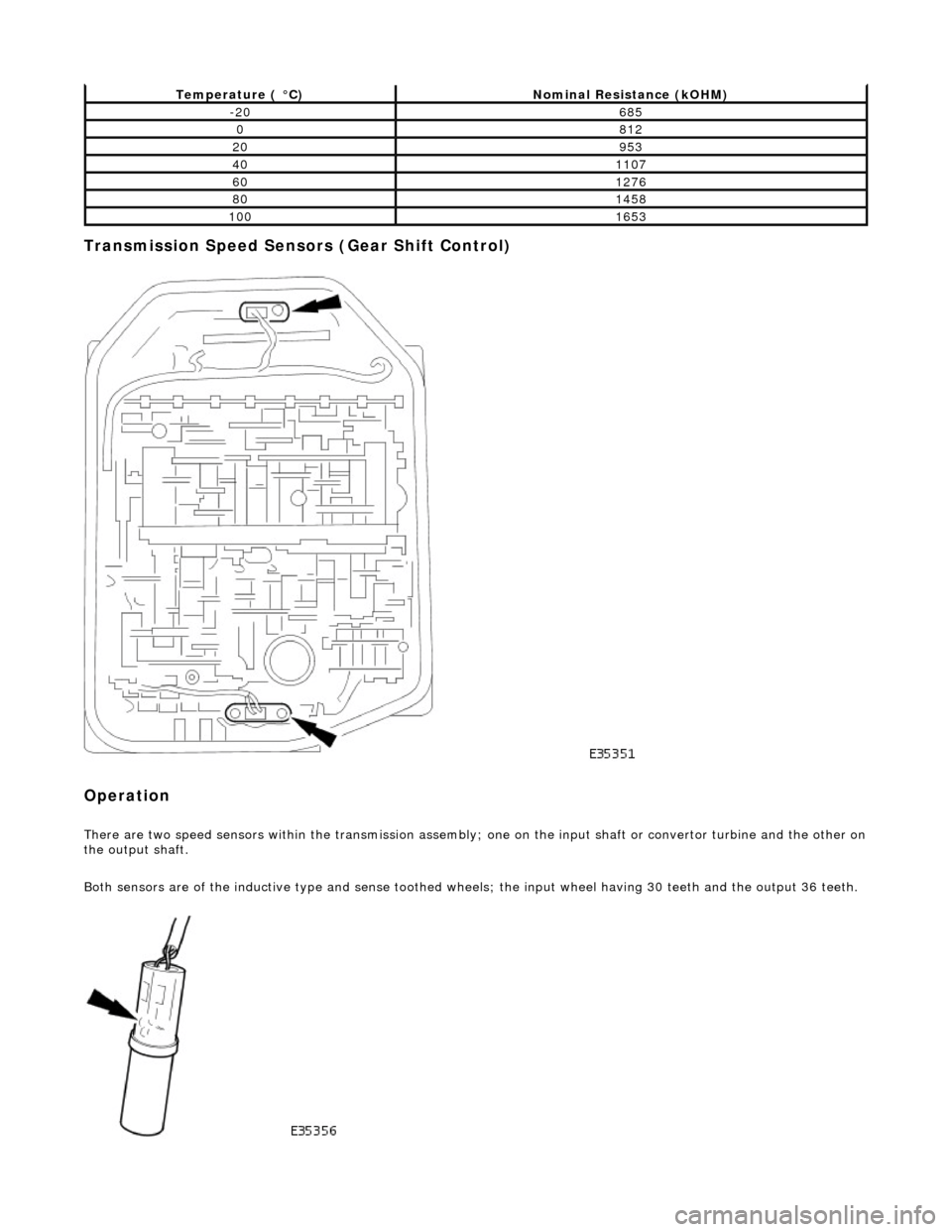
Operation
There are two speed sensors within the transmission assembly; one on the input shaft or convertor turbine and the other on the output shaft.
Both sensors are of the inductive type and sense toothed wheels; the input wheel having 30 teeth and the output 36 teeth.
Temperature ( °C)Nominal Resistance (kOHM)
-20685
0812
20953
401107
601276
801458
1001653
Page 1269 of 2490
2.2. Check on non-volatile diagnostic memory by wr iting a test pattern and then reading it back.
3. 3. Internal 'watchdog' hardware to check whether the TCM has crashed.
Transmission Control Module Supply Voltage
The TCM monitors battery and igni tion switched supply voltages.
A permanent supply is used to maintain a battery backed 'memor y'. Should this supply be cut, due to battery disconnection
perhaps, the 'adaptive shift' valu es will be lost. This will result in a small reduction in shift quality for a period until th e
adaptions are 're-learned'
The TCM will adopt 'limp home' mode as a result of the supply voltage being >16V or <7V with an engine speed >1600
rpm.
Should the ignition supply be >7V but <9V the TCM will hold the gear that it has currently selected. If after 2.5 seconds,
with the engine speed >1600 rpm, the voltage remains at this level, 'limp home' mode will be adopted. The 2.5 second
delay is built in to prevent reaction to a momentary voltage fluctuation.
Operation
CAUTION: Disconnection of the TCM and / or the vehicle batt ery will cause system adaptions to be lost; this may be
apparent by shift quality degradation. Fo llowing reconnection, a period of 'varied' driving will reinstate adaptions and thus
normal operation. Please ensure that the customer is made aware that the adaption period is variable and may occur after
handover, as the transmission re-learns the prevailing driving style.
• NOTE: Should the TCM fail, please ensure that the control housing cooling fan is operating correctly. Failure of the cooling
fan MUST be rectified before renewing the TCM and details of a fan fa ilure should accompany the returned TCM.
The TCM processes information received in both analogue and digital form, such as:
Transmission input speed Transmission output speed Throttle position Pedal demand Gear selector position Engine torque Engine speed Transmission oil temperature Mode switch
This information is then used by the TC M to control shift energy management and decide which shift program to implement
and which gear to select.
The TCM uses the various sensors and inpu ts to monitor the correct operation of the system an d is programmed to take
default action and inform the operator when a fault occurs.
Safety Functions
The safety functions are designed to safeguard against inappr opriate actions by the operator as well as against system
malfunctions. The system prevents reve rse gear from being engaged at high forward speeds and prevents manual
downshifting at excessive engine speeds; these functions are not operational in mechanical limp-home mode.
The TCM constantly monitors the transmissi on for faults. In the event of a problem the TCM will adopt a 'limp home' mode
in which only P R N D - (selector in D but only fourth gear is enabled) are available. The operator will be made aware of
certain faults by an in strument panel warning.
The electrical and diagnostic system has been designed such that system integrity is protected at all times, the safety
concept being based on th e following three points: