charger JAGUAR X308 1998 2.G Owner's Guide
[x] Cancel search | Manufacturer: JAGUAR, Model Year: 1998, Model line: X308, Model: JAGUAR X308 1998 2.GPages: 2490, PDF Size: 69.81 MB
Page 1004 of 2490

Engine Cooling - Water Pump4.0L SC V8 - AJ26
Remo
val and Installation
Remov
a
l
1.
Op
en the engine compartment and fit paintwork protection
sheets.
2. Drain the cooling system.
For additional information, refer to Cooling System Draining,
Filling and Bleedin
g
- Vehicles With
: Supercharger in this
section.
3. Remove the supercharger driv e belt. Refer to Operation
18.50.08.
4. Slacken the three screws whi
ch
secure the water pump pulley.
5. CAUTIO
N: When releasing the
belt tension, never apply
any torque in a clockwise direction to the pulley ce ntre bolt (left
hand thread) as it could subsequently loosen.
Remove the drive belt from the generator and accessory drive.
1. Use a spanner e.g. Churchill JD-230 or Snap On XDHM 1415, on the centre bo lt of the belt tensioner
idler pulley, to turn the adju ster assembly to the left
against spring tension.
2. Whilst holding the tensioner against spring tension, remove the drive belt from the generator pulley.
Release the tensioner sl owly and remove the
spanner.
Di
sconnect the belt from the ot
her pulleys, as necessary,
to move it clear of the pump pulley.
6. Remove t
he pulley from the water pump.
1. Remove the pulley securing screws.
2. Remove the pulley from the water pump.
7. Remove the water pump.
Page 1006 of 2490

4.
Fill
the cooling system.
For additional information, refer to Cooling System Draining,
Filling and Bleedin
g
- Vehicles With
: Supercharger in this
section.
Page 1007 of 2490

W
ater Pump Pulley Vehicles Without: Supercharger
26.50.05
Removal
1. Open the engine compartment and fit paintwork protection sheets.
2
. Slacken the three screws which secure the water pump pulley.
3
.
C
AUTION:
When releasing the belt tension, never apply any torque in a clockwise direction to the pulley
centre bolt (left hand thread) as it could subsequently loosen.
Remove the drive belt from the generator and accessory drive. 1. Use a spanner e.g. Churchill JD-230 or Snap On XDHM 1415, on the centre bolt of the belt tensioner idler pulley, to turn the adjuster assembly to the left against spring tension.
Page 1009 of 2490

W
ater Pump Pulley Vehicles With: Supercharger
26.50.05
Removal
1. Open the engine compartment and fit paintwork protection sheets.
2. Remove the supercharger drive belt. Refer to Operation <<18.50.08>>.
3
. Slacken the three screws which secure the water pump pulley.
4
.
C
AUTION:
When releasing the belt tension, never apply any torque in a clockwise direction to the pulley
centre bolt (left hand thread) as it could subsequently loosen.
Page 1011 of 2490
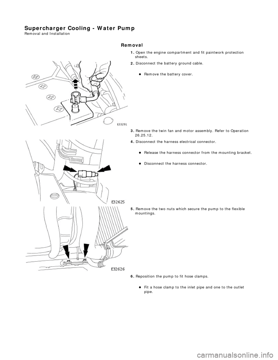
Supercharger Cooling - Water Pump
Re
moval and Installation
Remov
al
1.
O
pen the engine compartment and fit paintwork protection
sheets.
2. Di
sconnect the batt
ery ground cable.
R
emove the battery cover.
3. Remove the twin fan and motor assembly. Refer to Operation
26.25.12.
4. Disc
onnect the harness electrical connector.
R
elease the harness connector from the mounting bracket.
Disc
onnect the harness connector.
5. R
emove the two nuts which secure the pump to the flexible
mountings.
6. Reposition the pump to fit hose clamps.
Fi
t a hose clamp to the inlet pipe and one to the outlet
pipe.
Page 1014 of 2490
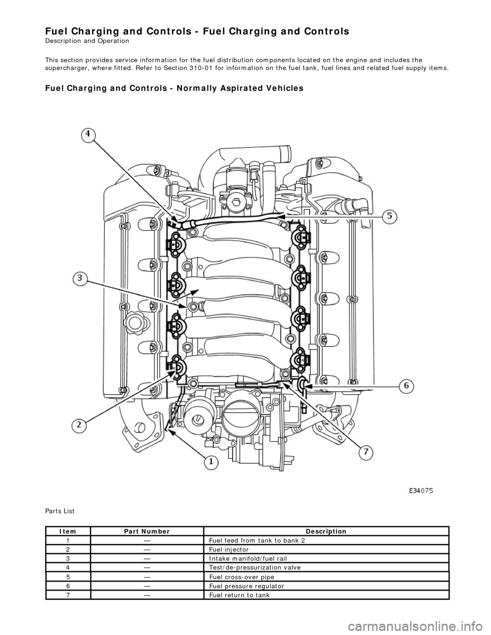
Fuel Char
ging and Controls - Fuel Charging and Controls
Description an
d Operation
This section provides service informatio n for the fuel distribution components located on the engine and includes the
supercharger, where fitted. Refer to Section 310-01 for informatio n on the fuel tank, fuel lines and related fuel supply items.
Fuel Charging and Controls -
Normally Aspirated Vehicles
P
a
rts List
It
e
m
Par
t
Number
De
scr
iption
1—F
u
el feed from tank to bank 2
2—Fue
l
injector
3—Inta
k
e manifold/fuel rail
4—Te
st
/de-pressurization valve
5—F
u
el cross-over pipe
6—F
u
el pressure regulator
7—F
u
el return to tank
Page 1016 of 2490
Pa
rts List
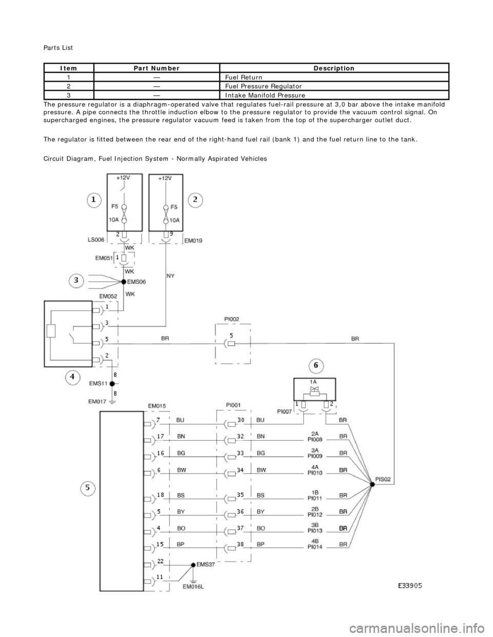
The pressure regulator is a diap hragm-operated valve that regula tes fuel-rail pressure at 3,0 bar above the intake manifold
pressure. A pipe connects the throttle induction elbow to the pressure regulator to provide the vacuum control signal. On
supercharged engines, the pressure regulator vacuum feed is taken from the top of the supercharger outlet duct.
The regulator is fitted between the rear end of the right-hand fuel rail (bank 1) and the fuel return line to the tank.
Circuit Diagram, Fuel Injection Syst em - Normally Aspirated Vehicles
Ite
m
Par
t
Number
De
scr
iption
1—F
u
el Return
2—F
u
el Pressure Regulator
3—Inta
k
e Manifold Pressure
Page 1026 of 2490
REFE
R to Section 310
-00
Fu
el
Sy
ste
m
- General
Information
.
Check f o
r DTCs indicating a sensor
fault,
REFER to Section 303
-14 El
ectronic
Engine
C
ontrols
.
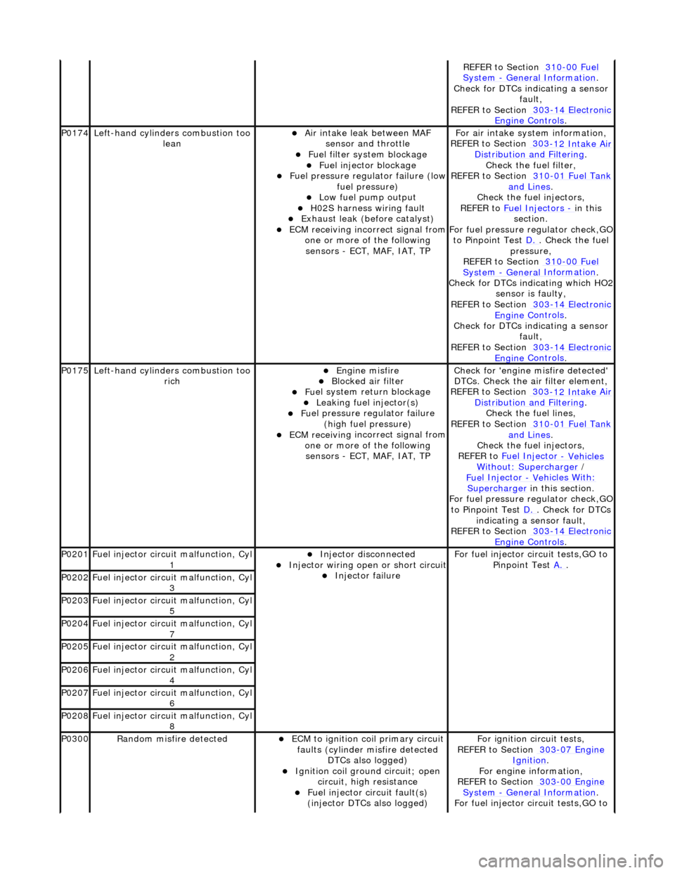
P0174
Left-hand cyl i
nders combustion too
lean
Air in
take leak between MAF
sensor and throttle
F u
el filter system blockage
F
u
el injector blockage
F
u
el pressure regulator failure (low
fuel pressure)
Low f u
el pump output
H0
2S harness wiri
ng fault
E
x
haust leak (before catalyst)
ECM receivi
n
g incorrect signal from
one or more of the following sensors - ECT, MAF, IAT, TP
F o
r air intake sy
stem information,
REFER to Section 303
-12 Int
ake Air
Distribu tion and Filterin
g
.
Check the fuel fi lter,
REF
ER to Section 310
-01
Fu
el Tank
and Lines.
Chec k the
fuel injectors,
REFER to Fuel Injectors
- in t h
is
section.
For fuel pressure regulator check,GO
to Pinpoint Test D.
. Ch
eck the fuel
pressure,
REFER to Section 310
-00 Fu
el
Sy
ste
m
- General
Information
.
Check f o
r DTCs indicating which HO2
sensor is faulty,
REFER to Section 303
-14 El
ectronic
Engine
C
ontrols
.
Check f o
r DTCs indicating a sensor
fault,
REFER to Section 303
-14 El
ectronic
Engine
C
ontrols
.
P0175Left-hand cyli
nders combustion too
rich
Engine m
isfire
Bl
ocked air
filter
F
u
el system return blockage
Leak
i
ng fuel injector(s)
F
u
el pressure regulator failure
(high fuel pressure)
ECM receivi n
g incorrect signal from
one or more of the following sensors - ECT, MAF, IAT, TP
Check for 'en
gine misfire detected'
DTCs. Check the air filter element,
REFER to Section 303
-12 Int
ake Air
Distribu tion and Filterin
g
.
Chec k the
fuel lines,
REFER to Section 310
-01 Fu
el Tank
and Lines.
Chec k the
fuel injectors,
REFER to Fuel Injector
- Vehicles Wi
thout: Supercharger
/
Fue
l Injector
- Ve
hicles With
:
Supercharger
in this
section.
For fuel pressure regulator check,GO
to Pinpoint Test D.
. Check for DT
Cs
indicating a sensor fault,
REFER to Section 303
-14 El
ectronic
Engine
C
ontrols
.
P0201F
u
el injector circuit malfunction, Cyl
1
Injector discon n
ected
Inject
or wir
ing open or short circuit
Injector fail
ure
F
o
r fuel injector circuit tests,GO to
Pinpoint Test A.
.
P0202Fu
el injector circuit malfunction, Cyl
3
P0203F u
el injector circuit malfunction, Cyl
5
P0204F u
el injector circuit malfunction, Cyl
7
P0205Fu
el injector circuit malfunction, Cyl
2
P0206Fu
el injector circuit malfunction, Cyl
4
P0207F u
el injector circuit malfunction, Cyl
6
P0208F u
el injector circuit malfunction, Cyl
8
P0300Ran d
om misfire detected
ECM t
o
ignition coil primary circuit
faults (cylinder misfire detected DTCs also logged)
Ignition coil ground circuit; open
ci
rcuit, high resistance
F
u
el injector circuit fault(s)
(injector DTCs also logged)
F o
r ignition circuit tests,
REFER to Section 303
-07 En
gine
Ignition.
F or engi
ne information,
REFER to Section 303
-00 En
gine
Sy
ste
m
- General
Information
.
F o
r fuel injector circuit tests,GO to
Page 1028 of 2490
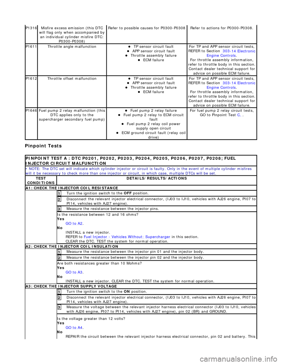
Pinpoint Tests
P1316Mi
sfire excess emission (this DTC
will flag only when accompanied by an individual cylinder misfire DTC: P0300-P0308)
Re
fer to possible causes for P0300-P0308
R
e
fer to actions for P0300-P0308.
P1611Thr
o
ttle angle malfunction
TP sensor
ci
rcuit fault
APP sensor circuit faul
t Throttle
assembly failure
ECM failu
r
e
F
or TP and APP
sens
or circuit tests,
REFER to Section 303
-14 El
ectronic
Engine
C
ontrols
.
F o
r throttle assembly information,
refer to throttle body in this section.
Contact dealer technical support for advice on possible ECM failure.
P1612Throttl e
offset malfunction
TP sensor
ci
rcuit fault
APP sensor circuit faul
t Throttle
assembly failure
ECM failu
r
e
F
or TP and APP
sens
or circuit tests,
REFER to Section 303
-14 El
ectronic
Engine
C
ontrols
.
F o
r throttle assembly information,
refer to throttle body in this section.
Contact dealer technical support for advice on possible ECM failure.
P1646Fu
el pump 2 relay malfunction (this
DTC applies only to the
supercharger secondary fuel pump)
Fu
el pump 2 relay failure
Fu
el pump 2 relay to ECM circuit
fault
Fu
el pump 2 relay coil power
supply open circuit
ECM ground circuit faul t (relay coil
drive)
For fuel pump 2 r
elay circuit tests,
GO to Pinpoint Test C.
.
PI
NPOINT TEST A : DTC P0201, P0202, P0203, P0204, P0205, P0206, P0207, P0208; FUEL
INJECTOR CIRCUIT MALFUNCTION
• NOTE
: The DTC set will indicate which cylinder injector or circ
uit is faulty. Only in the event of multiple cylinder misfires
will it be necessary to chec k more than one injector or circuit, in which case, multiple DTCs will be set.
TES
T
CONDITIONS
D E
TAILS/RESULTS/ACTIONS
A1
: CH
ECK THE INJECTOR COIL RESISTANCE
Turn the ignition swi
t
ch to the OFF
position.
1
Disconne
ct the relevant injector electrical connector
, (IJ03 to IJ10, vehicles with AJ26 engine, PI07 to
PI14, vehicles with AJ27 engine).
2
Meas ure t
he resistance between the injector pins.
3
Is
t
he resistance between 12 and 16 ohms?
Yes GO to A2
.
No
INST
ALL a new injector.
REFER to Fuel Injector
- Ve hicles With
out: Supercharger
in this
section.
CLEAR the DTC. TEST the system for normal operation.
A2: CHECK
THE INJECTOR COIL INSULATION
Meas
ure t
he resistance between the inje
ctor pin 01 and the injector body.
1
Measure t
he resistance between the inje
ctor pin 02 and the injector body.
2
Are both re
sistances greater than 10 Mohms?
Yes GO to A3
.
No
INST
ALL a new injector. CLEAR the DTC. TE
ST the system for normal operation.
A3: CHECK THE INJECTOR
SUPPLY VOLTAGE
Turn the ignition swi
t
ch to the ON
position.
1
Disconne
ct the relevant injector electrical connector
, (IJ03 to IJ10, vehicles with AJ26 engine, PI07 to
PI14, vehicles with AJ27 engine).
2
Meas ure t
he voltage between the relevant injector harness electrical connector (IJ03 to IJ10, vehicles
with AJ26 engine, PI07 to PI 14, vehicles with AJ27 engine), pin 02 (BR) and GROUND.
3
Is the volt
age greater than 12 volts?
Yes GO to A4
.
No
R
EPAIR the circuit between the relevant injector harn
ess electrical connector, pin 02 and battery. This
Page 1040 of 2490
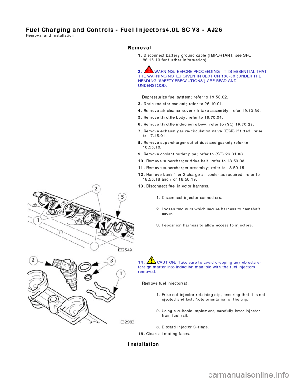
Fuel Char
ging and Controls - Fu
el Injectors4.0L SC V8 - AJ26
Remo
val and Installation
Remov
a
l
Installation
1. Disc onne
ct battery ground cable (IMPORTANT, see SRO
86.15.19 for further information).
2. WARNING: BEFORE PROCEEDING, IT IS ESSENTIAL THAT
THE WARNING NOTES GIVEN IN SECTION 100-00 (UNDER THE
HEADING 'SAFETY PRECAUTIONS') ARE READ AND
UNDERSTOOD.
Depressurize fuel syst em; refer to 19.50.02.
3. Drain radiator coolant; refer to 2
6.10.01.
4. Remove air cleaner cover / inta ke assembly; refer 19.10.30.
5. Remove throttle body; refer to 19.70.04.
6. Remove throttle induction elbo w; refer to (SC) 19.70.28.
7. Remove exhaust gas re-circulation valve (EGR) if fitted; refer
to 17.45.01.
8. Remove supercharger outlet duct and gasket; refer to
18.50.16.
9. Remove coolant outlet pipe; refer to (SC) 26.31.08 .
10. Remove supercharger drive belt; refer to 18.50.08.
11. Remove supercharger assembly; refer to 18.50.15.
12. Remove bank 1 or 2 charge air cooler as required; refer to
18.50.18 and / or 18.50.19.
13 . Di
sconnect fuel injector harness.
1. Disconnect injector connectors.
2. Loosen two nuts which se cure harness to camshaft
cover.
3. Reposition harness to al low access to injectors.
14. CAUTI
ON: Take care to avoi
d dropping any objects or
foreign matter into induction ma nifold with the fuel injectors
removed.
Remove fuel injector(s). 1. Prise out injector retaining clip, ensuring that it is not
ejected and lost. Note orientation of the clip.
2. Using a suitable implemen t, carefully lever injector
from fuel rail.
3. Discard injector O-rings.
15 . Cle
an all mating faces.