charger JAGUAR X308 1998 2.G Service Manual
[x] Cancel search | Manufacturer: JAGUAR, Model Year: 1998, Model line: X308, Model: JAGUAR X308 1998 2.GPages: 2490, PDF Size: 69.81 MB
Page 1041 of 2490
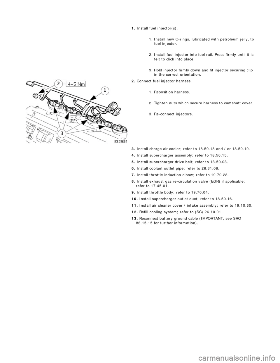
1.
Install
fuel injector(s).
1. Install new O-rings, lubricated with petroleum jelly, to
fuel injector.
2. Install fuel in jector into fuel rail. Press firmly until it is
felt to click into place.
3. Hold injector firmly down and fit injector securing clip
in the correct orientation.
2. Conne
ct fuel injector harness.
1. Reposition harness.
2. Tighten nuts which secure harness to camshaft cover.
3. Re-connect injectors.
3. Install charge air c ooler; refer to 18.50.18 and / or 18.50.19.
4. Install supercharger asse mbly; refer to 18.50.15.
5. Install supercharger driv e belt; refer to 18.50.08.
6. Install coolant outlet pi pe; refer to 26.31.08.
7. Install throttle induction elbow; refer to 19.70.28.
8. Install exhaust gas re-circulation valve (EGR) if applicable;
refer to 17.45.01.
9. Install throttle body ; refer to 19.70.04.
10. Install supercharger outlet duct; refer to 18.50.16.
11. Install air cleaner cover / intake assembly; re fer to 19.10.30.
12. Refill cooling system; refer to (SC) 26.10.01 .
13. Reconnect battery ground cable (IMPORTANT, see SRO
86.15.15 for further information).
Page 1052 of 2490

P a
rts List
All engine accessories are rigidly-mounted onto the cylinder block by means of accessory moun ting brackets on the left and
right-hand sides of the engine.
The left-hand bracket supports the air-cond itioning compressor and steering pump.
The right-hand bracket su pports the generator.
Dowels between the accessory mounting br ackets and the engine ensure that the accessory pulleys are accurately aligned
with the accessory drive belt.
A ccess
ory Drive on Supercharged Engines
The front
en
d accessory drive description and information for the
supercharged engine is identical to that given above. The
only difference is that the drive belt for the supercharger passes im mediately in front of the accessory drive belt. Therefore,
before any work can be done on the acce ssory drive belt and associated components, the supercharg er drive belt must first
be removed.
It e
m
Par
t
Number
De
scr
iption
1—R
i
ght Hand Mounting Bracket
2—Left H
and Mounting Bracket
Access
ory Mounting Brackets
Page 1054 of 2490

Accessory Drive - Accessory Drive Belt
4.0L SC V8 - AJ26
Re
mo
val and Installation
Remov
a
l
Installation
1.
Op
en the engine compartment and fit paintwork protection
sheets.
2. Remove the supercharger driv e belt, for access. Refer to
operation 18.50.08.
3. Check the belt wear indicator ma rks to confirm that the drive
belt is / is not within limits.
4. CAUTIO
N: When releasing the
belt tension, never apply
any torque in a clockwise direction to the pulley ce ntre bolt (left
hand thread) as it could subsequently loosen.
Remove the drive belt fro m the accessory drive.
1. Use a spanner e.g. Churchill JD-230 or Snap On XDHM 1415, on the centre bo lt of the belt tensioner
idler pulley, to turn the adju ster assembly to the left,
viewed from the front, against spring tension.
2. Whilst holding the tensioner against spring tension, remove the drive belt from the generator pulley.
Release the tensioner sl owly and remove the
spanner.
D i
sconnect the belt from the ot
her pulleys, as necessary.
1. Ins
tallation is the
reverse of the remova l procedure. Ensure
that the belt is correctly and sq uarely located on each pulley.
2. Refit the supercharger drive belt. Refer to operation 18.50.08.
Page 1056 of 2490

Accessory Drive - Accessory Drive Belt
Idler Pulley4.0L SC V8 - AJ26
Re
mo
val and Installation
I
n
stallation
1.
Op
en the engine compartment and fit paintwork protection
sheets.
2. Remove the supercharger driv e belt, for access. Refer to
operation 18.50.08.
3. Remove the accessory drive belt for access. Refer to Operation
(12.10.40)
4. Re
move the idler pulley.
1. Remove the securing bolt from the idler pulley.
2. Remove the idler pulley.
1. Installation is the reverse of the removal procedure. Tighten
the pulley securing bolt to 53-69 Nm. Ensure that the belt is
correctly and squarely lo cated on each pulley.
2. Refit the supercharger drive belt. Refer to operation 18.50.08.
Page 1058 of 2490

Accessory Drive - Accessory
Drive Belt Tensioner4.0L SC V8 - AJ26
Re
mo
val and Installation
I
n
stallation
1.
Op
en the engine compartment and fit paintwork protection
sheets.
2. Remove the supercharger driv e belt, for access. Refer to
operation 18.50.08.
3. Remove the accessory drive belt for access. Refer to Operation
(12.10.40)
4. Remove t
he tensioner assembly, which includes the tensioner
pulley..
1. Remove the bolt whic h secures the tensioner
assembly to the engine.
2. Remove the tensioner assembly.
1. Installation is the reverse of the removal procedure. Tighten
the tensioner assembly securing bolt to 38-48 Nm. Ensure that
the belt is correctly and squa rely located on each pulley.
2. Refit the supercharger drive belt. Refer to operation 18.50.08.
Page 1059 of 2490
Ac
cessory Drive - Supercharger Belt
Re
moval and Installation
Remov
al
Installation
1.
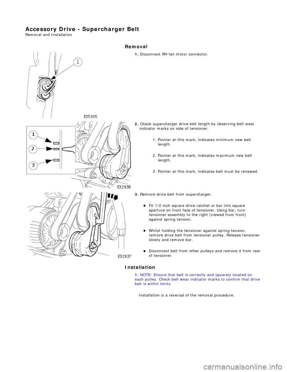
Di
sconnect RH fa
n motor connector.
2. Check superch
arger dr
ive belt length by observing belt wear
indicator marks on side of tensioner.
1. Pointer at this mark, indicates minimum new belt length.
2. Pointer at this mark, indicates maximum new belt length.
3. Pointer at this mark, indi cates belt must be renewed.
3. R
emove drive belt from supercharger.
F
it 1/2 inch square drive ratchet or bar into square
aperture on front face of tensioner. Using bar, turn
tensioner assembly to the right (viewed from front)
against spring tension.
Wh
ilst holding the tensione
r against spring tension,
remove drive belt fr om tensioner pulley. Release tensioner
slowly and remove bar.
D
isconnect belt from
other pulleys and remove it from rear
of tensioner.
1. NOTE: Ensure that belt is correctly and squarely located on
each pulley. Check belt wear indicator marks to confirm that drive
belt is within limits.
Installation is a reversal of the removal procedure.
Page 1060 of 2490
Access
ory Drive - Supercharger Belt Idler Pulley
Re
mo
val and Installation
Remov
a
l
Installation
1.
Re
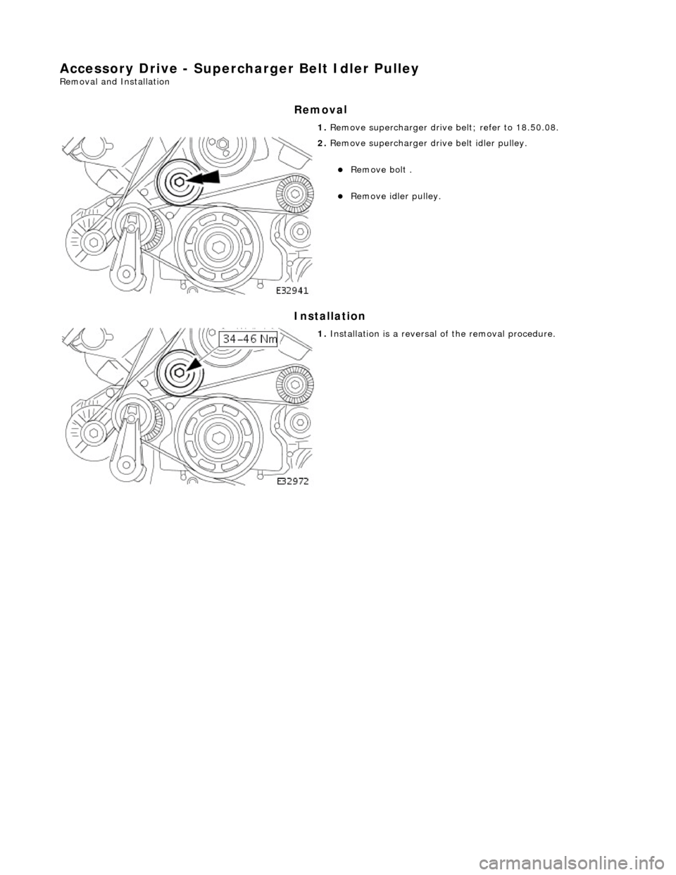
move supercharger drive belt; refer to 18.50.08.
2. Re
move supercharger drive belt idler pulley.
Re
mo
ve bolt .
R
e
move idler pulley.
1. Installation
is a reversal
of the removal procedure.
Page 1061 of 2490
Accessory Drive - Supercharger B
elt Tensioner
Re
moval and Installation
Remov
al
Installation
1.
R
emove twin fan and motor asse
mbly; refer to (SC) 26.25.12.
2. Remove supercharger drive belt; refer to 18.50.08.
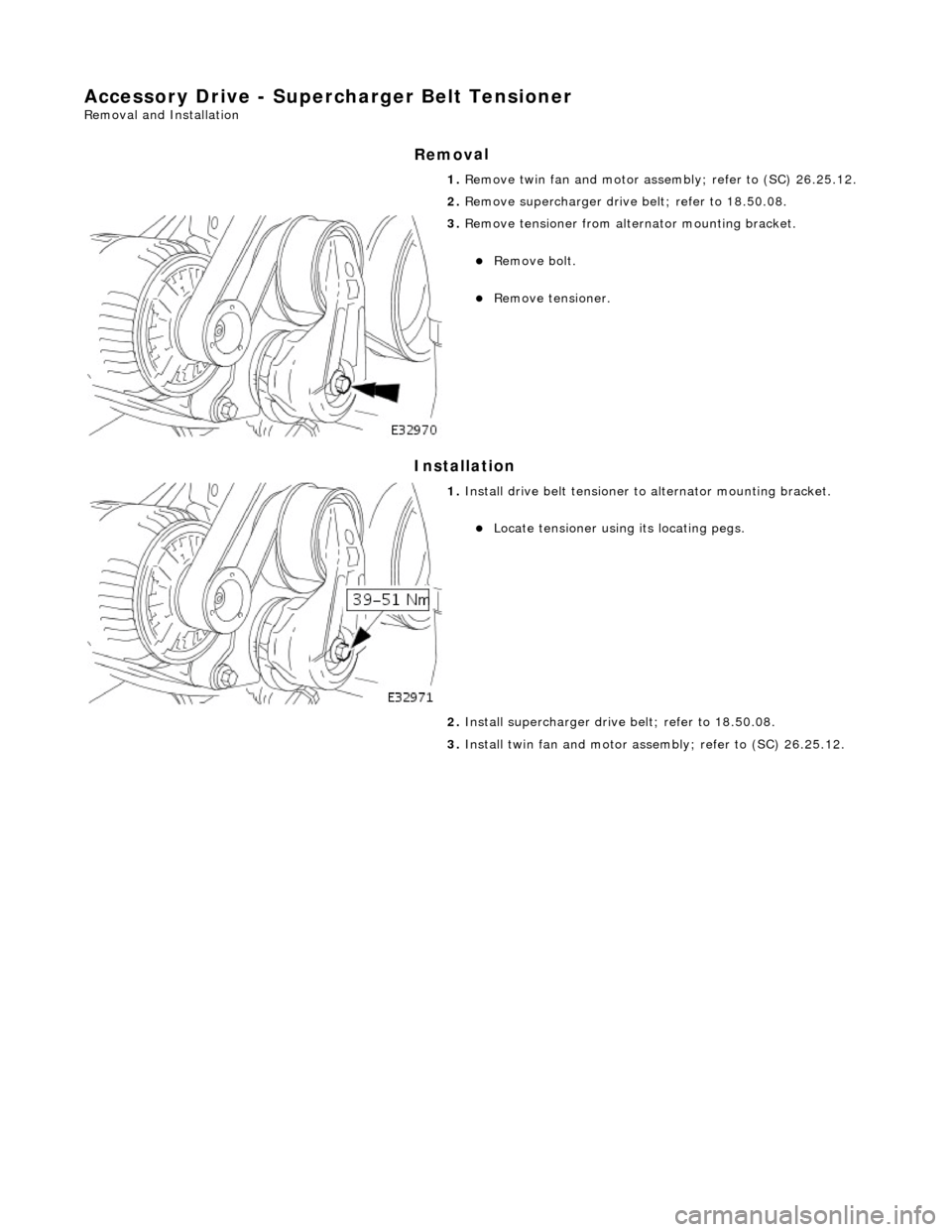
3. R
emove tensioner from altern
ator mounting bracket.
Re
move bolt.
R
emove tensioner.
1. Inst
all drive belt tensioner to
alternator mounting bracket.
Locat
e tensioner using its locating pegs.
2. Install supercharger driv e belt; refer to 18.50.08.
3. Install twin fan and motor asse mbly; refer to (SC) 26.25.12.
Page 1106 of 2490
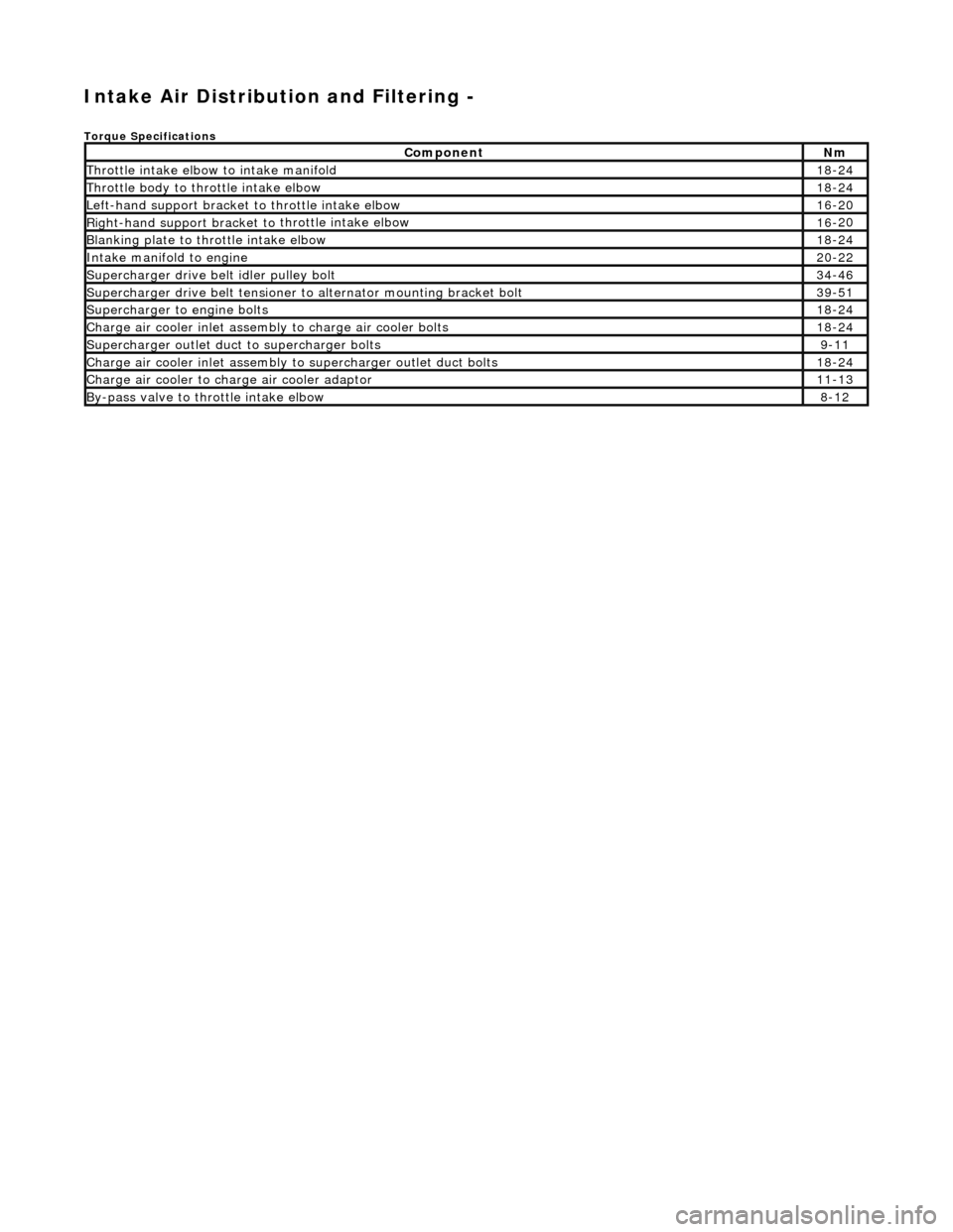
Intake Air Distribution and Filtering -
Torque Specificat
ions
Comp
onent
Nm
Thr
o
ttle intake elbow to intake manifold
18
-
24
Thro
tt
le body to throttle intake elbow
18
-
24
Left-hand support
bracket to
th
rottle intake elbow
16
-
20
Right-hand support
bracket to
throttle intake elbow
16
-
20
B
l
anking plate to throttle intake elbow
18
-
24
Inta
k
e manifold to engine
20
-
22
Supe
rcharger
drive belt idler pulley bolt
34
-
46
Supercharger
drive belt te
nsioner to alternator mounting bracket bolt
39
-
51
Supercharger
to eng
ine bolts
18
-
24
Charge air cooler in
let assembly to charge ai
r cooler bolts
18
-
24
Supercharger
outlet duct to supercharger bolts9-1
1
Charge air cooler in
let assembly to superchar
ger ou
tlet duct bolts
18-
24
Charge air cool
er to charge
air cooler adaptor
11
-
13
B
y
-pass valve to throttle intake elbow
8-
1
2
Page 1111 of 2490
the
intake elbow provide connections for vacuum actuators and are also used to redirect emissions into the engine.
On the right-hand side of the elbow a la rge diameter pipe connects to the brake servo. The smaller pipe provides a vacuum
feed to the fuel rail pressure regulator and throttle cruise control system. On the le ft-hand side of the elbow the front pipe
supplies vacuum control for the evaporative emissions system valves.
Emissions from the engine part load breather (bank 2) and pu rged fuel vapor from the EVAP valve are drawn via a common
T piece into the left-hand side of the intake elbow. Re-cir culated exhaust gas enters the intake elbow via the EGR valve
which is mounted directly on the rear of the elbow : where the EGR system is not used, a blanking plate is fitted.
The fuel system, throttle and emission control system s are described more fully in the relevant sections.
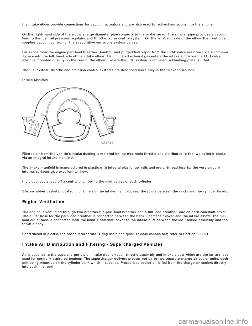
Intake Manifold
Filtered air from the vehicle's intake ducting is metered by th e electronic throttle and distributed to the two cylinder banks
via an integral intake manifold.
The intake manifold is manufactured in plastic with integral plastic fuel rails and metal-thread inserts; the very smooth
internal surfaces give excellent air flow.
Individual ducts lead off a central chamber to the inlet valves of each cylinder.
Silicon-rubber gaskets, loca ted in channels in the intake manifold, seal th e joints between the ducts and the cylinder heads.
Engine Ventilation
The e
ngine is ventilated through two brea
thers; a part-load breather and a full-load breather, one on each camshaft cover.
The outlet hose for the part-load breather is connected between the bank 2 camshaft cover and the intake elbow. The full-
load outlet hose is connected from the bank 1 camshaft cover to the intake duct between the MAF sensor assembly and the
throttle body.
Constructed in plastic, the hoses incorporate O-ring seal s and quick-release connectors; refer to Section 303-01.
I
ntake Air Distribution and Filtering - Supercharged Vehicles
Ai
r is supplied to the supercharger via an
intake cleaner/duct, throttle assembly and intake elbow which are similar to those
used for normally aspirated engines. The su percharger delivers pressurized air to two separate charge air cooler units, each
unit being mounted on the cy linder bank which it supplies. Pr essurized cooled air is fed from the charge air coolers directly
into each inlet port.