height JAGUAR X308 1998 2.G Owner's Guide
[x] Cancel search | Manufacturer: JAGUAR, Model Year: 1998, Model line: X308, Model: JAGUAR X308 1998 2.GPages: 2490, PDF Size: 69.81 MB
Page 2356 of 2490

Bumpers - Rear Bumper Cover
Removal and Installation
Removal
Installation
1. Position vehicle on 4-post lift.
2. Remove battery cover and disc onnect ground cable from
battery terminal. Refer to 86.15.19.
3. WARNING: THE REAR BUMPER IS CLOSE TO THE
EXHAUST PIPES WHICH MAY BE HOT. CARE MUST THEREFORE BE
EXERCISED WHEN WORKING IN THIS VICINITY.
Raise vehicle to working height.
4. If fitted, disconnect sidemarker lamp harness multiplugs and
position clear of armatures.
5. Slacken and remove bumper to strut securing bolts.
6. With assistance, carefully slide bumper clear of guide blocks
and remove from vehicle.
1. Release retaining clips and remo ve sidemarker lamps/reflectors from bumper.
2. Remove bumper blades.
1. Slacken and remove three screws securing each blade
Page 2359 of 2490
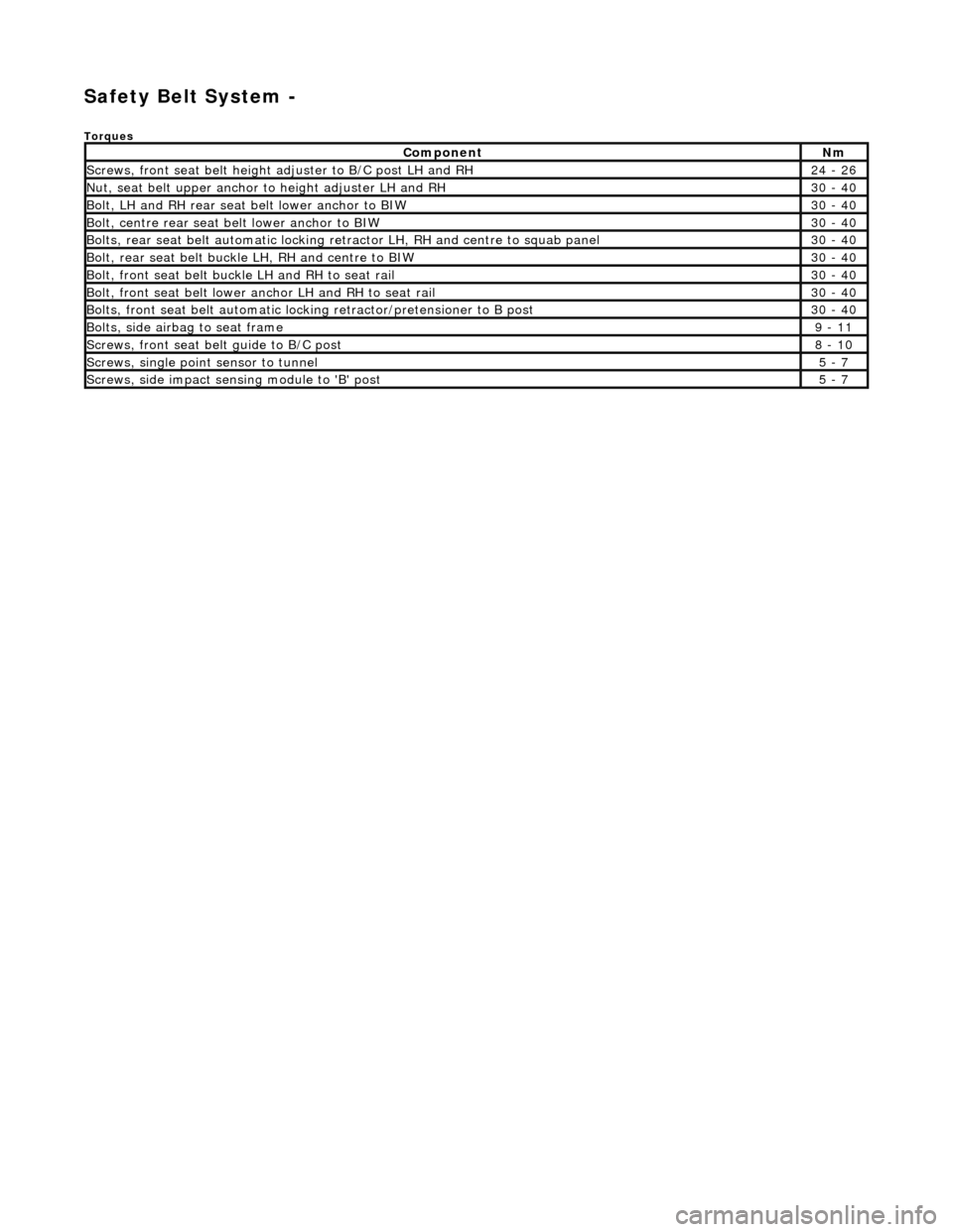
Safety Belt System -
Torques
ComponentNm
Screws, front seat belt height adjuster to B/C post LH and RH24 - 26
Nut, seat belt upper anchor to height adjuster LH and RH30 - 40
Bolt, LH and RH rear seat belt lower anchor to BIW30 - 40
Bolt, centre rear seat belt lower anchor to BIW30 - 40
Bolts, rear seat belt automatic locking re tractor LH, RH and centre to squab panel30 - 40
Bolt, rear seat belt buckle LH, RH and centre to BIW30 - 40
Bolt, front seat belt buckle LH and RH to seat rail30 - 40
Bolt, front seat belt lower an chor LH and RH to seat rail30 - 40
Bolts, front seat belt automatic lock ing retractor/pretensioner to B post30 - 40
Bolts, side airbag to seat frame9 - 11
Screws, front seat belt guide to B/C post8 - 10
Screws, single point sensor to tunnel5 - 7
Screws, side impact sens ing module to 'B' post5 - 7
Page 2360 of 2490
Safety Belt System - Safety Belt System
Description and Operation
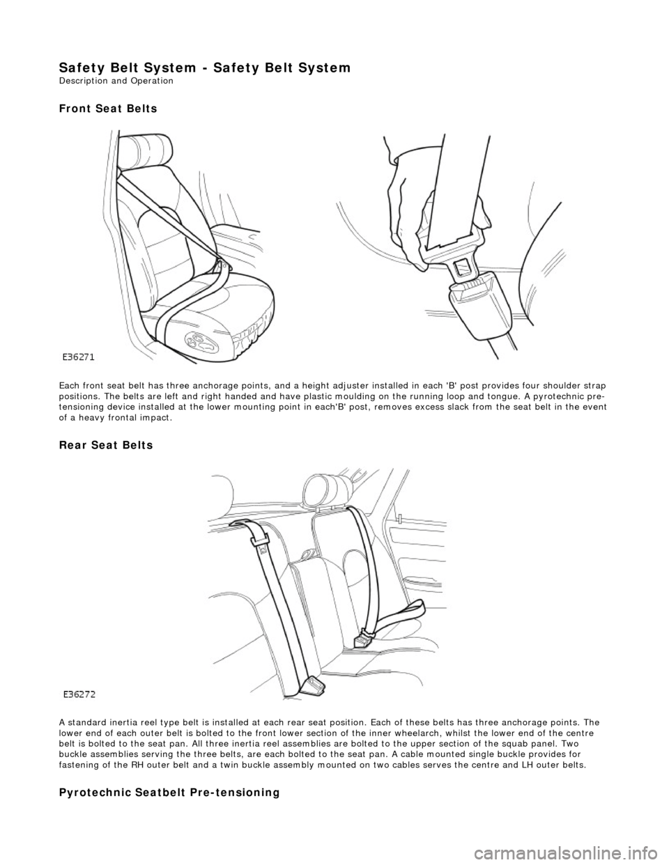
Front Seat Belts
Each front seat belt has three anchorage points, and a height adjuster installed in each 'B' post provides four shoulder strap
positions. The belts are left and right ha nded and have plastic moulding on the r unning loop and tongue. A pyrotechnic pre-
tensioning device installed at the lower mounting point in each 'B' post, removes excess slack from the seat belt in the event
of a heavy frontal impact.
Rear Seat Belts
A standard inertia reel type belt is installed at each rear seat position. Each of these belts has three anchorage points. The
lower end of each outer belt is bolted to the front lower section of the inner wheelarch, whilst the lower end of the centre
belt is bolted to the seat pan. All thr ee inertia reel assemblies are bolted to the upper section of the squab panel. Two
buckle assemblies serving the three belts, are each bolted to the seat pan. A cable mounted single buckle provides for
fastening of the RH outer belt and a twin buckle assembly mounted on two cables serves the centre and LH outer belts.
Pyrotechnic Seatbelt Pre-tensioning
Page 2362 of 2490
Safety Belt System - Front Safety Belt Retractor
Removal and Installation
Removal
• WARNINGS:
IF A SEAT BELT PRETENSIONING UNIT IS INADVERTENTLY RUPTURED AND INGESTION AND/OR INHALATION
OCCURS, FIRST AID MUST BE APPLIED AND MEDICAL ADVICE SOUGHT.
NO ATTEMPT MUST BE MADE TO DISMANTLE A PRETENSIONING RETRACTOR UNIT. THERE ARE NO SERVICEABLE
PARTS.
WHEN HANDLING A RETRACTOR UNIT PISTON HOUSING, THE PISTON MUST ALWAYS BE POINTED DOWNWARDS
AND AWAY FROM ONE'S SELF AND OTHER PERSONNEL AND FINGERS MUST BE KEPT AWAY FOM THE TAKE-UP SPOOL
MECHANISM.
ANY PRETENSIONING UNIT DROPPED FROM A HEIGHT GREA TER THAN 0.3M (12 INCHES) MUST NOT BE FITTED TO A
VEHICLE.
UNACTIVATED PRE-TENSIONING UNIT COMPONENTS CONTAIN A SOLID, FLAMMABLE MATERIAL.
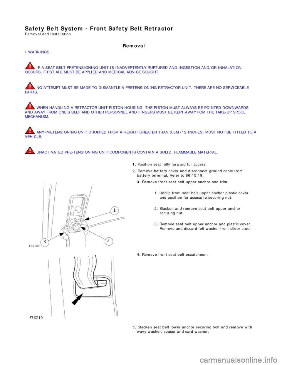
1. Position seat fully forward for access.
2. Remove battery cover and disc onnect ground cable from
battery terminal. Refer to 86.15.19.
3. Remove front seat belt upper anchor and trim.
1. Unclip front seat belt upper anchor plastic cover
and position for access to securing nut.
2. Slacken and remove se at belt upper anchor
securing nut.
3. Remove seat belt upper anchor and plastic cover. Remove and discard felt washer from slider stud.
4. Remove front seat belt escutcheon.
5. Slacken seat belt lower anchor securing bolt and remove with
wavy washer, spacer and card washer.
Page 2364 of 2490
and fully tighten
securing bolts.
2. Position seat belt guide on 'B' post and fit and fully tighten the
two securing screws.
3. Position 'B' post casing in vehicle and pass seat belt anchor
plates and tongue through aperture.
4. Fit 'B' post casing. Refer to 76.13.08.
5. Fit securing bolt and wavy washer to seat belt anchor. Fit
spacer and card washer to bolt and fit and fully tighten securing
bolt.
6. Fit felt washer with paper ba cking outwards, onto height
adjuster stud
7. Position upper anchor on height adjuster stud, fit and tighten
securing nut and fit pl astic cap over nut.
8. Connect ground cable to battery terminal and fit battery cover.
Refer to 86.15.15.
9. Return seat to original position.
Page 2367 of 2490
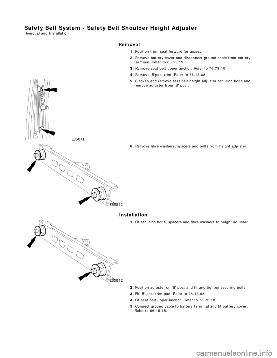
Safety Belt System - Safety Belt Shoulder Height Adjuster
Removal and Installation
Removal
Installation
1.
Position front seat forward for access.
2. Remove battery cover and disconnect ground cable from battery
terminal. Refer to 86.15.19.
3. Remove seat belt upper anchor. Refer to 76.73.10
4. Remove 'B'post trim. Refer to 76.13.08.
5. Slacken and remove seat belt heig ht adjuster securing bolts and
remove adjuster from 'B' post.
6. Remove fibre washers, spacers an d bolts from height adjuster.
1. Fit securing bolts, spacers and fi bre washers to height adjuster.
2. Position adjuster on 'B' post an d fit and tighten securing bolts.
3. Fit 'B' post trim pad. Refer to 76.13.08.
4. Fit seat belt upper an chor. Refer to 76.73.10
5. Connect ground cable to battery terminal and fit battery cover.
Refer to 86.15.15.
Page 2368 of 2490
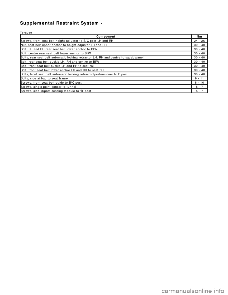
Supplemental Restraint System -
Torques
ComponentNm
Screws, front seat belt height adjuster to B/C post LH and RH24 - 26
Nut, seat belt upper anchor to height adjuster LH and RH30 - 40
Bolt, LH and RH rear seat belt lower anchor to BIW30 - 40
Bolt, centre rear seat belt lower anchor to BIW30 - 40
Bolts, rear seat belt automatic locking re tractor LH, RH and centre to squab panel30 - 40
Bolt, rear seat belt buckle LH, RH and centre to BIW30 - 40
Bolt, front seat belt buckle LH and RH to seat rail30 - 40
Bolt, front seat belt lower an chor LH and RH to seat rail30 - 40
Bolts, front seat belt automatic lock ing retractor/pretensioner to B post30 - 40
Bolts, side airbag to seat frame9 - 11
Screws, front seat belt guide to B/C post8 - 10
Screws, single point sensor to tunnel5 - 7
Screws, side impact sens ing module to 'B' post5 - 7
Page 2370 of 2490
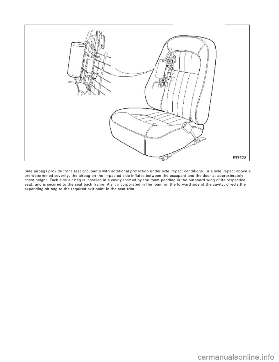
Side airbags provide front seat occupants with additional protection under side impa ct conditions. In a side impact above a
pre-determined severity, the ai rbag on the impacted side inflates between the occupant an d the door at approximately
chest height. Each side air bag is installe d in a cavity formed by the foam padding in the outboard wing of its respective
seat, and is secured to the seat back frame . A slit incorporated in the foam on the forward side of the cavity, directs the
expanding air bag to the required exit point in the seat trim.