height JAGUAR X308 1998 2.G Owner's Manual
[x] Cancel search | Manufacturer: JAGUAR, Model Year: 1998, Model line: X308, Model: JAGUAR X308 1998 2.GPages: 2490, PDF Size: 69.81 MB
Page 2046 of 2490
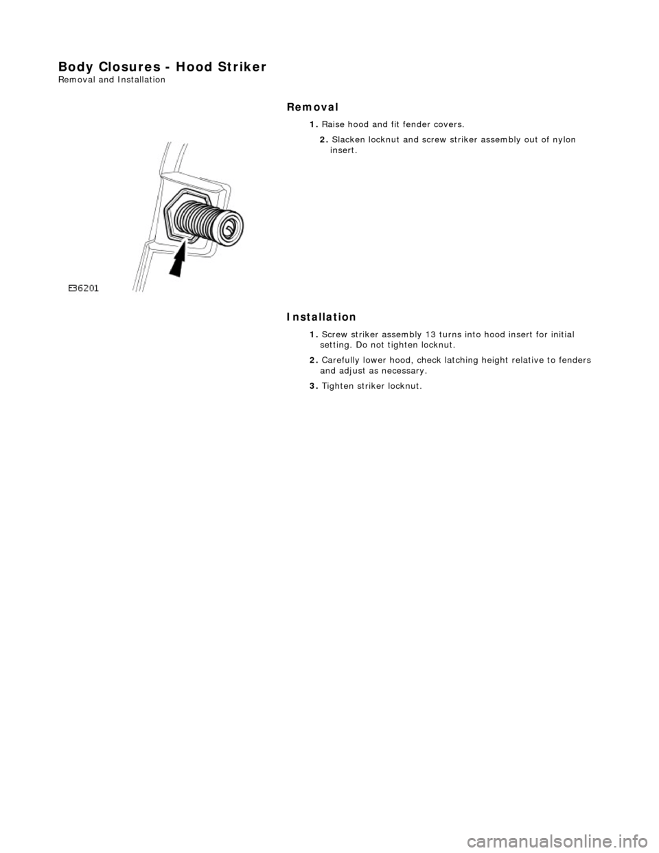
Body Closures - Hood Striker
Removal and Installation
Removal
Installation
1.
Raise hood and fit fender covers.
2. Slacken locknut and screw stri ker assembly out of nylon
insert.
1. Screw striker assembly 13 turns into hood insert for initial
setting. Do not tighten locknut.
2. Carefully lower hood, ch eck latching height relative to fenders
and adjust as necessary.
3. Tighten strike r locknut.
Page 2119 of 2490

Rear View Mirrors - Interior Mirror Mounting Block
Removal and Installation
Removal
Installation
1. Remove battery cover and disc onnect ground cable from
battery terminal. Refer to 86.15.19.
2. Position a protective cover over top of facia.
3. Remove roof console for ac cess. Refer to 76.13.69.90.
4. Remove rain sensor unit. Refer to Section 501.16.
5. Remove mirror from mounting block. Refer to 76.10.51 or
76.10.56 (electrochromic).
6. Apply a suitable solvent around edge of mounting block.
7. Commencing at the top and exercising care to avoid windshield
damage, use a thin plastic knife to ease block free.
8. Using a suitable solvent, clean residual adhesive from block
mounting area.
1. Using masking tape, mark block mounting area on windshield.
2. Apply Permabond F Grade 5 Initiator to mounting area of
windshield.
3. Apply a bead of Permabond F246 to bottom and each vertical
side of block over 2/3 of block height.
Page 2121 of 2490
Seating - Seats Description and Operation
Front Seats
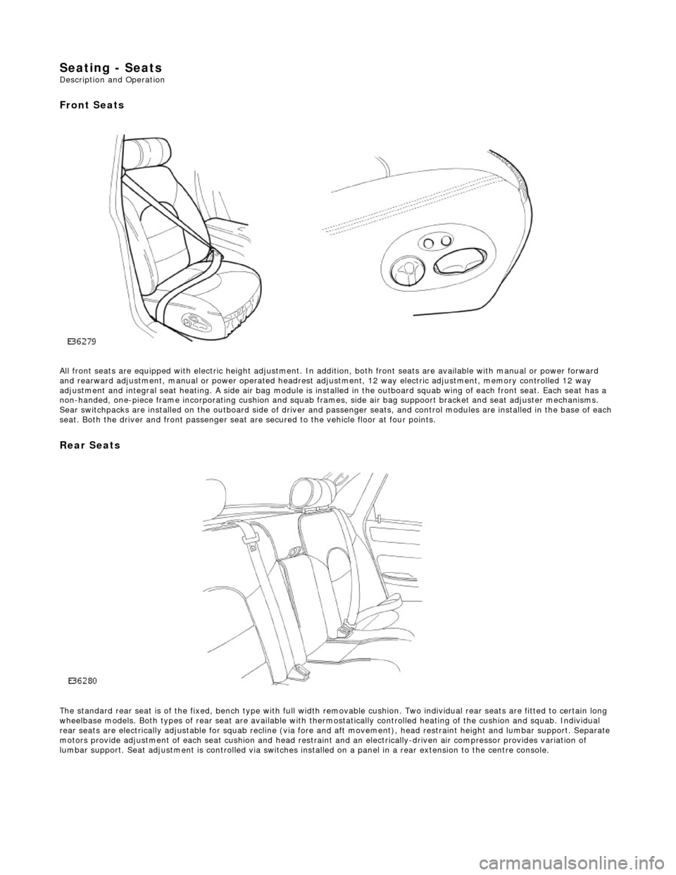
All front seats are equipped with electric height adjustment. In addition, both front seats are available with manual or power forward
and rearward adjustment, manual or powe r operated headrest adjustment, 12 way elec tric adjustment, memory controlled 12 way
adjustment and integral seat heating. A side air bag module is installed in the outboard squab wing of each front seat. Each se at has a
non-handed, one-piece frame incorporating cushion and squab frames , side air bag suppoort bracket and seat adjuster mechanisms.
Sear switchpacks are installed on the outboa rd side of driver and passenger seats, and control modules are installed in the bas e of each
seat. Both the driver and front passenger seat ar e secured to the vehicle floor at four points.
Rear Seats
The standard rear seat is of the fixed, bench type with full wi dth removable cushion. Two individual rear seats are fitted to certain long
wheelbase models. Both types of rear seat are available with thermostatically controlled heating of the cushion and squab. Indi vidual
rear seats are electrically adjustable for squab recline (via fore and aft moveme nt), head restraint height and lumbar support. Separate
motors provide adjustment of each seat cushion and head restraint and an electrica lly-driven air compressor provides variation of
lumbar support. Seat adjustment is controll ed via switches installed on a panel in a rear extension to the centre console.
Page 2219 of 2490
Instrument Panel and Console - Instrument Panel and Instrument Panel
Console
Description and Operation
Fascia
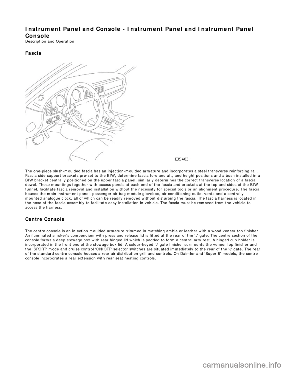
The one-piece slush-moulded fascia has an injection-moulded ar mature and incorporates a steel transverse reinforcing rail.
Fascia side support brackets pre-set to th e BIW, determine fascia fore and aft, and height position s and a bush installed in a
BIW bracket centrally positioned on the upper fascia panel, similarly determines the correct transverse location of a fascia
dowel. These mountings together with access panels at each en d of the fascia and brackets at the top and sides of the BIW
tunnel, facilitate fascia removal and instal lation without the necessity for special tools or an alignment procedure. The fasci a
houses the main instrument panel, pass enger air bag module glovebox, air conditioning outlet vents and a centrally
mounted analogue clock, all of which can be readily removed wi thout disturbing the fascia. The fascia harness is located in
the nose of the fascia assembly to facilitate easy installati on in vehicle. The fascia must be removed from the vehicle to
access the harness.
Centre Console
The centre console is an injection moulded armature trimmed in matching ambla or leather with a wood veneer top finisher.
An iluminated smoker's compendium with pr ess and release lid is fitted at the rear of the 'J' gate. The centre section of the
console forms a deep stowage box with rear hinged lid which is padded to form a central arm rest. A hinged cup holder is
incorporated in the front end of the stowage box lid. A colour-keyed 'J' gate finisher surmounts the veneer top finisher and
the 'SPORT' mode and cruise control 'ON/OFF' selector switches are situated immediately to the rear of the 'J' gate. The rear
of the standard centre console houses a re ar air distribution grill and controls. On Daimler and 'Super 8' models, the centre
console incorporates a rear extensio n with rear seat heating controls.
Page 2344 of 2490
Bumpers - Front Bumper
Removal and Installation
Removal
WARNING: ENSURE THAT ALL PERSONNEL AND EQUIPMENT ARE CLEAR OF AREA BEFORE OPERATING RAMP.
1. Position vehicle on 4-post ramp.
2. Remove battery cover and disc onnect ground cable from
battery terminal. Refer to 86.15.19
3. Remove radiator surround and grill. Refer to 76.55.15 and
76.55.03.
4. Raise ramp to working height.
5. Using wheel-free lifts, remove front wheels.
6. Remove wheelarch liners for access.
7. Remove undertray. Refer to 76.22.90.
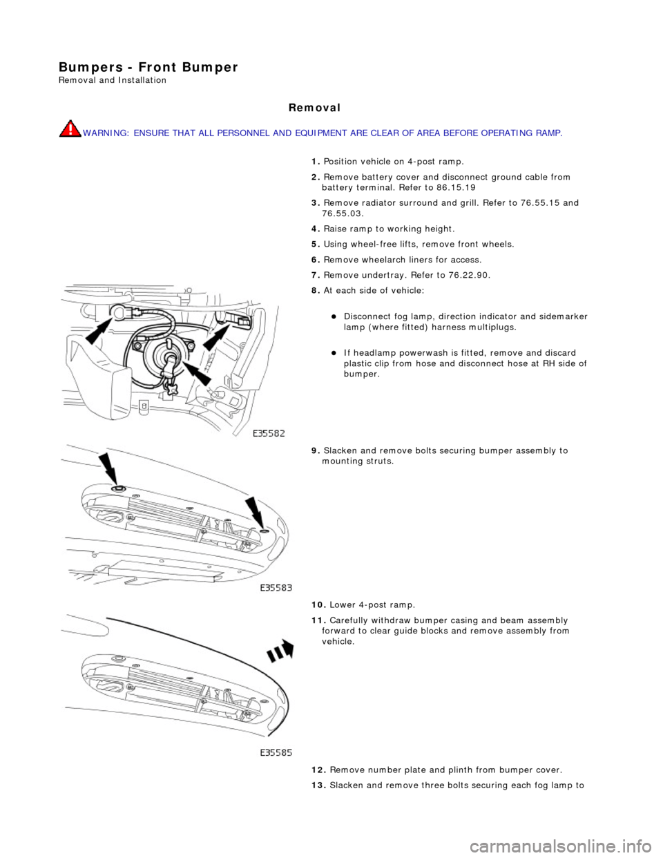
8. At each side of vehicle:
Disconnect fog lamp, directio n indicator and sidemarker
lamp (where fitted) harness multiplugs.
If headlamp powerwash is fitted, remove and discard
plastic clip from hose and disconnect hose at RH side of
bumper.
9. Slacken and remove bolts securing bumper assembly to
mounting struts.
10. Lower 4-post ramp.
11. Carefully withdraw bumper casing and beam assembly
forward to clear guide blocks and remove assembly from
vehicle.
12. Remove number plate and plinth from bumper cover.
13. Slacken and remove three bolts securing each fog lamp to
Page 2347 of 2490
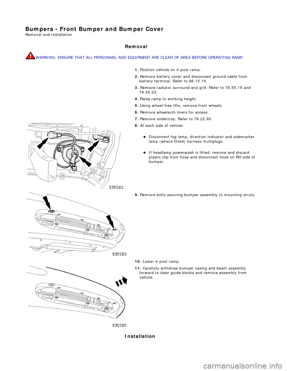
Bumpers - Front Bumper and Bumper Cover
Removal and Installation
Removal
WARNING: ENSURE THAT ALL PERSONNEL AND EQUIPMENT ARE CLEAR OF AREA BEFORE OPERATING RAMP.
Installation
1. Position vehicle on 4-post ramp.
2. Remove battery cover and disc onnect ground cable from
battery terminal. Refer to 86.15.19.
3. Remove radiator surround and grill. Refer to 76.55.15 and
76.55.03.
4. Raise ramp to working height.
5. Using wheel-free lifts, remove front wheels.
6. Remove wheelarch liners for access.
7. Remove undertray. Refer to 76.22.90.
8. At each side of vehicle:
Disconnect fog lamp, directio n indicator and sidemarker
lamp (where fitted) harness multiplugs.
If headlamp powerwash is fitted, remove and discard
plastic clip from hose and disconnect hose on RH side of
bumper.
9. Remove bolts securing bumper assembly to mounting struts.
10. Lower 4-post ramp.
11. Carefully withdraw bumper casing and beam assembly
forward to clear guide blocks and remove assembly from
vehicle.
Page 2348 of 2490

1.
WARNING: ENSURE THAT ALL PERSONNEL AND
EQUIPMENT ARE CLEAR OF AREA BEFORE OPERATING RAMP.
Carefully slide bumper assembly onto fender guide blocks.
2. Raise ramp to working height.
3. Install but do not fully tighten bo lts securing bumper to struts.
4. Check clearance between top of bumper and bottom of fender.
If necessary, remove bumper, adjust guide blocks to achieve
correct clearance and refit bumper.
5. Connect harness multiplugs to foglamps, direction indicators
and where fitted side marker lamps.
6. Install harnesses in retaining clips at each side of cover.
7. Install powerwash hoses to jet assemblies and secure with new
plastic clips. Refer to Section 501.16.
8. Install radiator grill and su rround. refer to 76.55.03 and
76.55.15.
9. Check and as necessary adjust bumper cover to fender,
headlamps and radiator grill surround clearances. Refer to
Description and Operation in this section.
10. Fully tighten bumper assembly to strut securing bolts.
11. Install wheelarch liners.
12. Install undertray. Refer to 76.22.90.
13. Lower 4-post ramp.
14. Install road wheels and lower wheel-free lifts.
Page 2349 of 2490
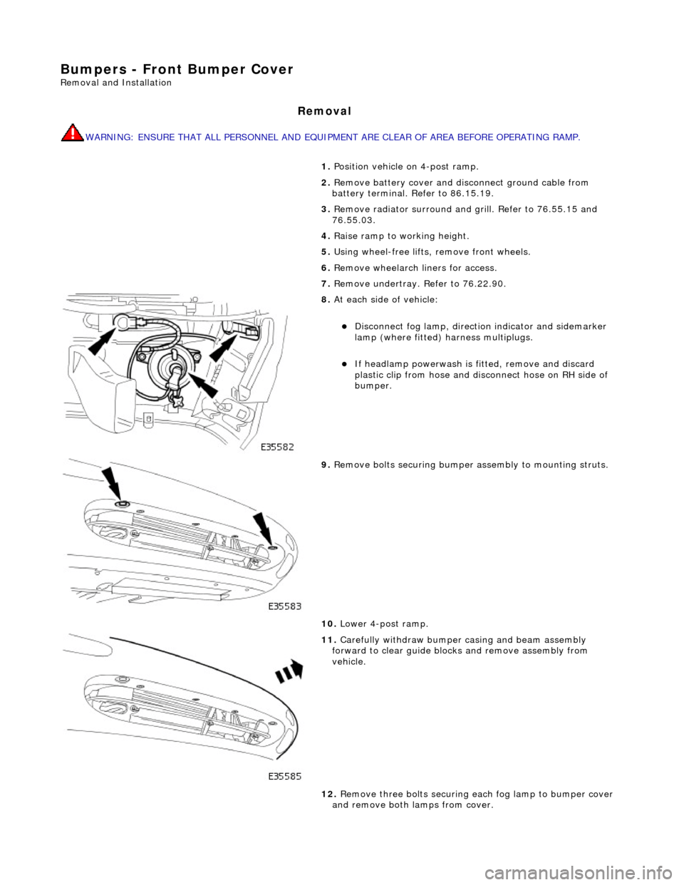
Bumpers - Front Bumper Cover
Removal and Installation
Removal
WARNING: ENSURE THAT ALL PERSONNEL AND EQUIPMENT ARE CLEAR OF AREA BEFORE OPERATING RAMP.
1. Position vehicle on 4-post ramp.
2. Remove battery cover and disc onnect ground cable from
battery terminal. Refer to 86.15.19.
3. Remove radiator surround and grill. Refer to 76.55.15 and
76.55.03.
4. Raise ramp to working height.
5. Using wheel-free lifts, remove front wheels.
6. Remove wheelarch liners for access.
7. Remove undertray. Refer to 76.22.90.
8. At each side of vehicle:
Disconnect fog lamp, directio n indicator and sidemarker
lamp (where fitted) harness multiplugs.
If headlamp powerwash is fitted, remove and discard
plastic clip from hose and disconnect hose on RH side of
bumper.
9. Remove bolts securing bumper assembly to mounting struts.
10. Lower 4-post ramp.
11. Carefully withdraw bumper casing and beam assembly
forward to clear guide blocks and remove assembly from
vehicle.
12. Remove three bolts securing each fog lamp to bumper cover
and remove both lamps from cover.
Page 2351 of 2490
Installation
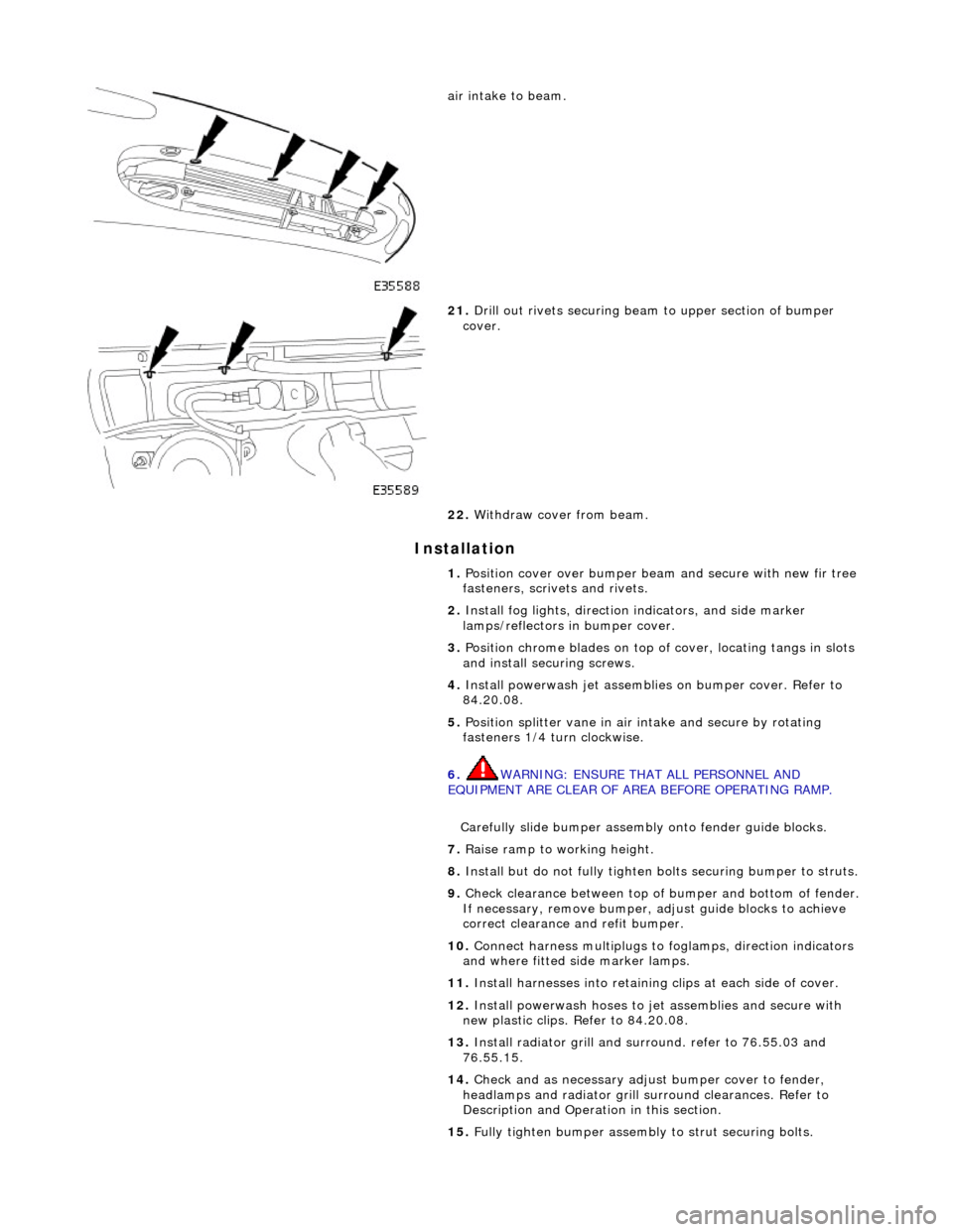
air intake to beam.
21. Drill out rivets securing beam to upper section of bumper
cover.
22. Withdraw cover from beam.
1. Position cover over bumper beam and secure with new fir tree
fasteners, scrivets and rivets.
2. Install fog lights, direction indicators, and side marker
lamps/reflectors in bumper cover.
3. Position chrome blades on top of cover, locating tangs in slots
and install securing screws.
4. Install powerwash jet assemblies on bumper cover. Refer to
84.20.08.
5. Position splitter vane in air intake and secure by rotating
fasteners 1/4 turn clockwise.
6. WARNING: ENSURE THAT ALL PERSONNEL AND
EQUIPMENT ARE CLEAR OF AREA BEFORE OPERATING RAMP.
Carefully slide bumper assembly onto fender guide blocks.
7. Raise ramp to working height.
8. Install but do not fully tighten bo lts securing bumper to struts.
9. Check clearance between top of bumper and bottom of fender.
If necessary, remove bumper, adjust guide blocks to achieve
correct clearance and refit bumper.
10. Connect harness multiplugs to foglamps, direction indicators
and where fitted side marker lamps.
11. Install harnesses into retaining clips at each side of cover.
12. Install powerwash hoses to jet assemblies and secure with
new plastic clips. Refer to 84.20.08.
13. Install radiator grill and su rround. refer to 76.55.03 and
76.55.15.
14. Check and as necessary adjust bumper cover to fender,
headlamps and radiator grill surround clearances. Refer to
Description and Operation in this section.
15. Fully tighten bumper assembly to strut securing bolts.
Page 2354 of 2490

Bumpers - Rear Bumper
Removal and Installation
Removal
1. Position vehicle on 4-post lift.
2. Remove battery cover and disc onnect ground cable from
battery terminal. Refer to 86.15.19.
3. WARNING: THE REAR BUMPER IS CLOSE TO THE
EXHAUST PIPES WHICH MAY BE HOT. CARE MUST THEREFORE BE
EXERCISED WHEN WORKING IN THIS VICINITY.
Raise vehicle to working height.
4. Disconnect sidemarker lamp ha rness multiplugs and position
clear of armatures.
5. Slacken and remove bumper to strut securing bolts.
6. With assistance, carefully slide bumper clear of guide blocks
and remove from vehicle.
7. Release retaining clips and remo ve sidemarker lamps/reflectors from bumper.
8. Remove bumper blades.
1. Slacken and remove three screws securing each blade
to bumper cover.