sensor JAGUAR X308 1998 2.G Owner's Guide
[x] Cancel search | Manufacturer: JAGUAR, Model Year: 1998, Model line: X308, Model: JAGUAR X308 1998 2.GPages: 2490, PDF Size: 69.81 MB
Page 160 of 2490

8. Inst
all special tool 204-111 in road spring.
Slacken tool
adjuster to suit spring length.
Fit adaptor and th
rust collar.
Positi
on stem of tool in center of spring passing dowel
through slot in su spension turret.
9. WA
RNING: WHEN TURNING TOOL ADJUSTER, ENSURE
THAT TOOL STEM DOES NOT ROTATE AND DISTURB POSITION
OF DOWEL IN SUSPENSION TURRET.
Engage dowel of special tool 204-111 in suspension turret and
rotate to position across slot.
10 . Lower veh
icle onto stands.
11 . R
otate tool adjuster to tension spring.
12. Remove wheel speed sensor se curing screw and withdraw
sensor from vertical link.
Page 164 of 2490

4. Po
sition tie rod ball joint taper
pin on steering arm and install
and tighten securing nut to 71-85Nm.
5. Instal
l wheel speed sensor.
Positi
on wheel speed sensor on vertical link.
Inst
al
l sensor securing bolt
and tighten to 8-10Nm.
6. Remove wire temporarily securing vertical link to road spring.
7. Install br ake disc.
8. Re
lease tension on road spring.
Ro
tate adjuster of special tool 204-111 to release spring
tension.
R e
move special tool and adaptor from spring.
9. Position new link ass
embly on
lower wishbone and install but
do not tighten bolt.
10. Position new link arm ball joint stud in stabilizer bar and
install but do not tighten nut.
Page 166 of 2490

Rear Su
spension -
Lubric
ants, Fluids, Sealants and Adhesives
Torques
UnitSp
ecification
Loctite27
0
Greas eShell Retin a
x 'A'
Greas
eCastro l 'NT
R'
Com
p
onent
Nm
N
u
t - hub to axle shaft
3
04 -
336
Nu
t -
hub carrier pivot pin
88
-
118
Bol
t
- ABS sensor to hub carrier
8-1
0
Nu
t - stabilizer bar link to lower wishbone.
30
-40
Nu
t - stabilizer bar to link assembly.
30
-40
Bolts -
monostrut to body mounting brackets
88
-
118
Bolt
s
- monostrut to wishbone tie assembly
77
-
103
Bolts
- bu
mp stop to body
26
-34
Bol t
- damper lower mounting
80
-
100
N
u
t - damper top
31
-39
Bolts -
damper mounting plate to body
17
-23
Page 171 of 2490

Rear
Suspension - Rear Susp
ension and Axle Assembly
Re
moval and Installation
Remov
al
1.
CAUTI
ON: Replacement of nuts and bolts: Various
thread-locking devices are used on nuts and bolts throughout the
vehicle. These devices restrict the number of times a nut or bolt
can be used.
For additional informat ion, refer to Section 100
-0
0 General
Informati
on
.
R
aise the rear of the vehicle
and support on axle stands.
For additional informat ion, refer to Section 100
-0
2 Jacking and
Liftin
g
.
2.
R
emove the rear wheels.
For additional informat ion, refer to Section 204
-04
Wheels and
Tire
s
.
3. CAUTI
ON: Do not suspend the caliper from the brake
hose as this will damage the hose.
• NOTE: Right-hand shown, left-hand similar
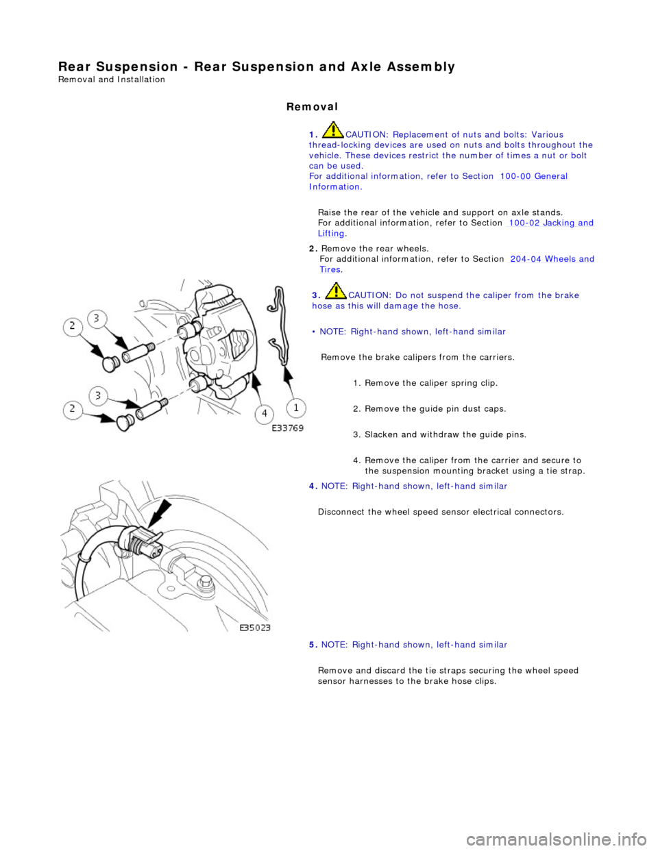
Remove the brake calipers from the carriers.
1. Remove the caliper spring clip.
2. Remove the guide pin dust caps.
3. Slacken and withdr aw the guide pins.
4. Remove the caliper from the carrier and secure to the suspension mounting bracket using a tie strap.
4. NOTE
: Right-hand shown, left-hand similar
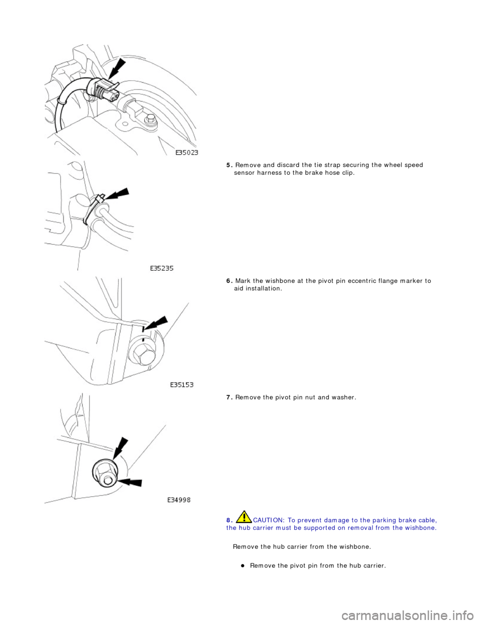
Disconnect the wheel speed sensor electrical connectors.
5. NOTE: Right-hand shown, left-hand similar
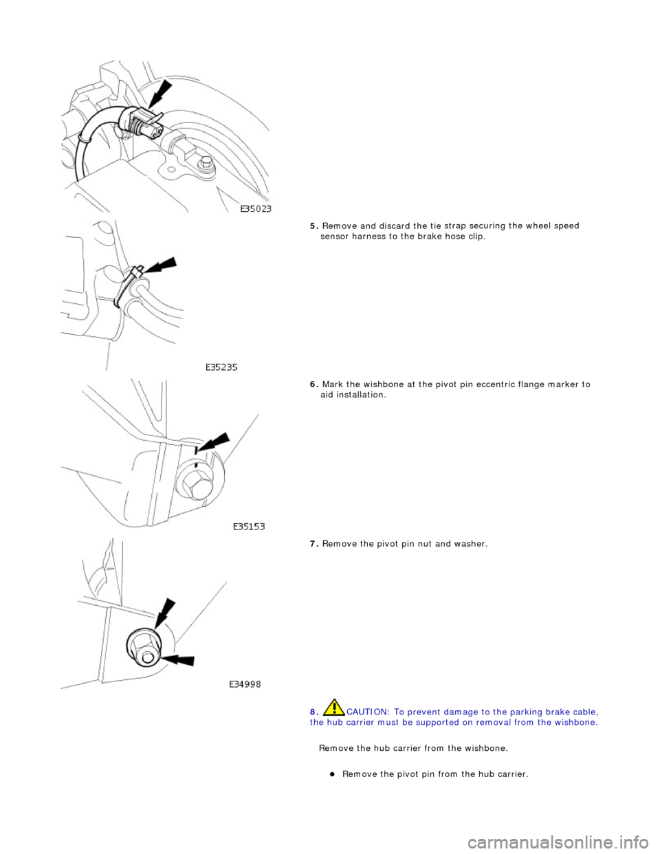
Remove and discard th e tie straps securing the wheel speed
sensor harnesses to the brake hose clips.
Page 179 of 2490

18
.
Install the brake caliper on to the carrier.
1. Position the caliper asse mbly on to the carrier.
2. Install the guide pins and tighten to 25-30 Nm.
3. Install the dust caps.
4. Install the brake caliper spring clip.
19
.
Connect the wheel speed sensor electrical connector.
20
.
Using a new tie strap, secure the wheel speed sensor harness
to the brake hose clip.
21. Install the rear wheels.
For additional informat ion, refer to Section 204
-04
Wheels and
Tire
s
.
22
.
Remove the axle stands and lower the vehicle.
For additional informat ion, refer to Section 100
-0
2 Jacking and
Liftin
g
.
23
.
Check and adjust the rear whee l alignment as necessary.
For additional informat ion, refer to Section 204
-00
Suspension
Sy
stem
- General
Information
.
Page 180 of 2490

Rear Su
spension - Rear Shock Absorber
Re
mo
val and Installation
Remov
a
l
S
p
ecial Tool(s)
Spri
ng C
ompressors
204-179 (JD 199)
Spri ng Re
taining straps
204-179-1 (JD 199-1)
1. CAUTION: Replacement of nuts and bolts: Various
thread-locking devices are used on nuts and bolts throughout the
vehicle. These devices restrict the number of times a nut or bolt
can be used.
For additional informat ion, refer to Section 100
-00
General
Informati
o
n
.
R a
ise the rear of the vehicle
and support on axle stands.
For additional informat ion, refer to Section 100
-02
Jacking and
Liftin
g.
2. Re
move the relevant rear wheel.
For additional informat ion, refer to Section 204
-04 W
heels and
Tire
s.
3. CAUTIO
N: Do not suspend the caliper from the brake
hose as this will damage the hose.
Remove the brake caliper from the carrier.
1. Remove the caliper spring clip.
2. Remove the guide pin dust caps.
3. Slacken and withdr aw the guide pins.
4. Remove the caliper from the carrier and secure to the suspension mounting bracket using a tie strap.
4. Disc
onnect the wheel speed sensor electrical connector.
Page 181 of 2490

5. Remove an
d discard the tie st
rap securing the wheel speed
sensor harness to the brake hose clip.
6. Mark the wi
shbone at the pivot
pin eccentric flange marker to
aid installation.
7. Remove the
pivot pin nut and washer.
8. CAUTION: To prevent damage to the parking brake cable,
the hub carrier must be supported on removal from the wishbone.
R
emove the hub carrie
r from the wishbone.
R
emove the pivot pin from the hub carrier.
Page 190 of 2490

22. R
elease the tie strap securing the brake caliper to the
suspension mounting bracket.
23 . Install
the brake caliper on to the carrier.
1. Position the caliper asse mbly on to the carrier.
2. Install the guide pins and tighten to 25-30 Nm.
3. Install the dust caps.
4. Install the brake caliper spring clip.
24 . Conne
ct the wheel speed sensor electrical connector.
25 . U
sing a new tie strap, secure the wheel speed sensor harness
to the brake hose clip.
26. Install the rear wheel.
For additional informat ion, refer to Section 204
-04 W
heels and
Tire
s.
27 .
Remove the
axle stands
and lower the vehicle.
For additional informat ion, refer to Section 100
-02
Jacking and
Liftin
g.
Page 195 of 2490

Rear
Suspension - Spring
Re
moval and Installation
Remov
al
S
pecial Tool(s)
Spri
ng Compressors
204-179 (JD 199)
Spri
ng Retaining straps
204-179-1 (JD 199-1)
1. CAUTION: Replacement of nuts and bolts: Various
thread-locking devices are used on nuts and bolts throughout the
vehicle. These devices restrict the number of times a nut or bolt
can be used.
For additional informat ion, refer to Section 100
-0
0 General
Informati
on
.
R
aise the rear of the vehicle
and support on axle stands.
For additional informat ion, refer to Section 100
-0
2 Jacking and
Liftin
g
.
2.
R
emove the relevant rear wheel.
For additional informat ion, refer to Section 204
-04
Wheels and
Tire
s
.
3. CAUTI
ON: Do not suspend the caliper from the brake
hose as this will damage the hose.
Remove the brake caliper from the carrier.
1. Remove the caliper spring clip.
2. Remove the guide pin dust caps.
3. Slacken and withdr aw the guide pins.
4. Remove the caliper from the carrier and secure to the suspension mounting bracket using a tie strap.
4. Di
sconnect the wheel speed sensor electrical connector.
Page 196 of 2490

5. Remove an d discard the tie
st
rap securing the wheel speed
sensor harness to the brake hose clip.
6. Mark the wi shbone at the
pivot
pin eccentric flan ge marker to
aid installation.
7. Remove the pivot pin nu
t and washer.
8. CAUTION: To prevent damage to the parking brake cable,
the hub carrier must be supported on removal from the wishbone.
Re
move the hub carrie
r from the wishbone.
Re
move the pivot pin from the hub carrier.