Steering column JAGUAR X308 1998 2.G Service Manual
[x] Cancel search | Manufacturer: JAGUAR, Model Year: 1998, Model line: X308, Model: JAGUAR X308 1998 2.GPages: 2490, PDF Size: 69.81 MB
Page 1848 of 2490
Control Components - Remote Climate Control ModuleRHD RWD
Removal and Installation
Removal
1. Position the driver's seat fully rearward
2. Position the steering column DOWN and fully EXTENDED
3. Disconnect the battery ground lead
4. Lower steering column cowl 76.46.03
5. Upper steering column cowl 76.46.02
6. Knee bolster, driver's side 76.46.11
7. Position the steering in the 'straight ahead'
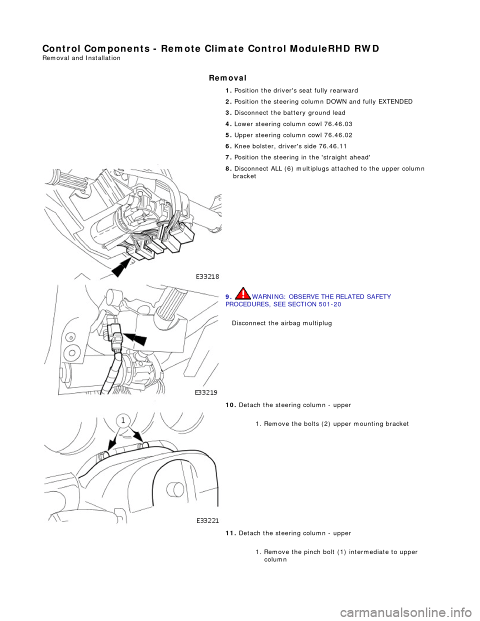
8. Disconnect ALL (6) multiplugs attached to the upper column
bracket
9. WARNING: OBSERVE THE RELATED SAFETY
PROCEDURES, SEE SECTION 501-20
Disconnect the airbag multiplug
10. Detach the steering column - upper
1. Remove the bolts (2 ) upper mounting bracket
11. Detach the steering column - upper
1. Remove the pinch bolt (1) intermediate to upper column
Page 1858 of 2490
In
stallation
8.
Slac ken an
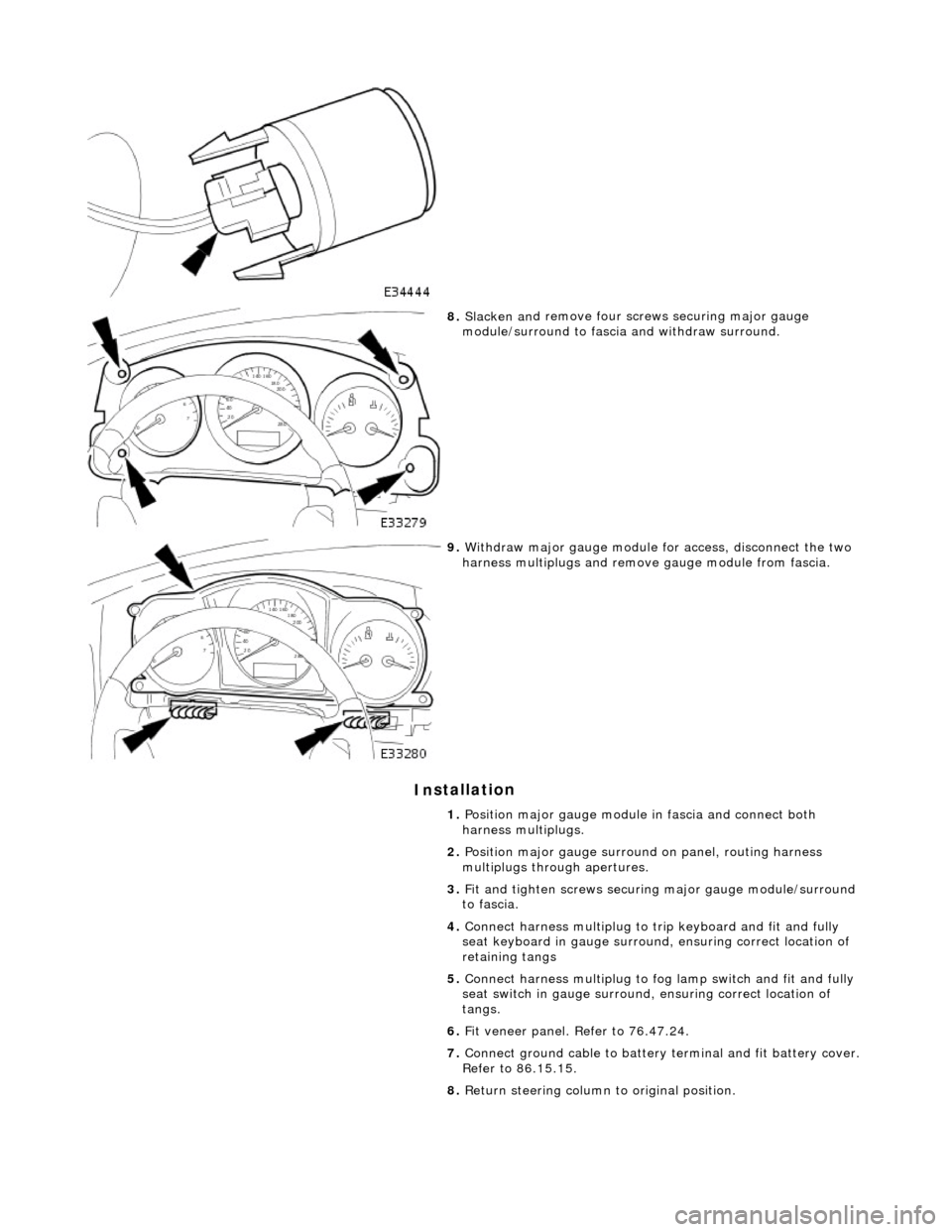
d remove four screws securing major gauge
module/surround to fascia and withdraw surround.
9. With draw major gau
ge module fo
r access, disconnect the two
harness multiplugs and remove gauge module from fascia.
1. Position major gauge module in fascia and connect both
harness multiplugs.
2. Position major gauge surround on panel, routing harness
multiplugs through apertures.
3. Fit and tighten screws securing major gauge module/surround
to fascia.
4. Connect harness multiplug to tr ip keyboard and fit and fully
seat keyboard in gauge surround, ensuring correct location of
retaining tangs
5. Connect harness multiplug to fog lamp switch and fit and fully
seat switch in gaug e surround, ensuring correct location of
tangs.
6. Fit veneer panel. Refer to 76.47.24.
7. Connect ground cable to battery terminal and fit battery cover.
Refer to 86.15.15.
8. Return steering column to original position.
Page 1919 of 2490
Exterior Lighting - Exterior Lighting
Description and Operation
A multi-function switch located on the left stalk of the steering column switch assembly permits selection of either parking
(side), headlamps, auto-headlamp or off. Selection of a particular mode provides the appropriate input to the body
processor module (BPM).
Where the auto headlamp function is incorporated, a light sensor in the interior rear view mirror monitors ambient light and
provides an input to the BPM. The BPM responds by switching the low beam headlamps on or off as appropriate for the
prevailing light conditions.
The front and rear fog lamp switch is located on the fascia outboard of the steering column.
Front Lamps
Headlamp assembly
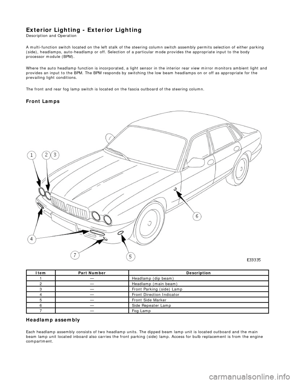
Each headlamp assembly consists of tw o headlamp units. The dipped beam lamp unit is located outboard and the main
beam lamp unit located inboard also carries the front parking (side) lamp. Access for bulb replacement is from the engine
compartment.
ItemPart NumberDescription
1—Headlamp (dip beam)
2—Headlamp (main beam)
3—Front Parking (side) Lamp
4—Front Direction Indicator
5—Front Side Marker
6—Side Repeater Lamp
7—Fog Lamp
Page 1977 of 2490
Heelboard Fuse Box - Left hand side
Trunk Fuse Box
105Radio telephone, rear courtesy lamp/map light.
1120Air conditioning right-hand blower relay.
125In-car entertainment.
1325Right-hand rear door control module.
1425Cigar lighters.
1525Right-hand door control module.
16-Not used.
1715Sunroof.
1825Right-hand and left-hand seat heaters.
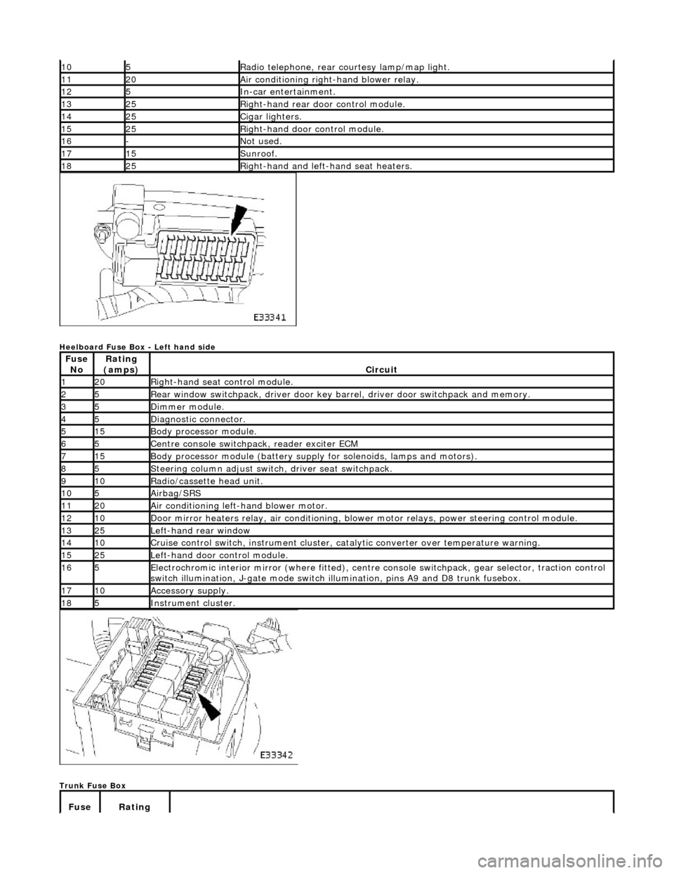
Fuse NoRating
(amps)Circuit
120Right-hand seat control module.
25Rear window switchpack, driver door key ba rrel, driver door switchpack and memory.
35Dimmer module.
45Diagnostic connector.
515Body processor module.
65Centre console switchpack, reader exciter ECM
715Body processor module (battery supply for solenoids, lamps and motors).
85Steering column adjust switch, driver seat switchpack.
910Radio/cassette head unit.
105Airbag/SRS
1120Air conditioning left-hand blower motor.
1210Door mirror heaters relay, air conditioning, blow er motor relays, power steering control module.
1325Left-hand rear window
1410Cruise control switch, instrument cluster, catalytic converter over temperature warning.
1525Left-hand door control module.
165Electrochromic interior mirror (where fitted), centre console switchpack, gear selector, traction control
switch illumination, J-gate mode switch illumination, pins A9 and D8 trunk fusebox.
1710Accessory supply.
185Instrument cluster.
Fuse Rating
Page 2008 of 2490
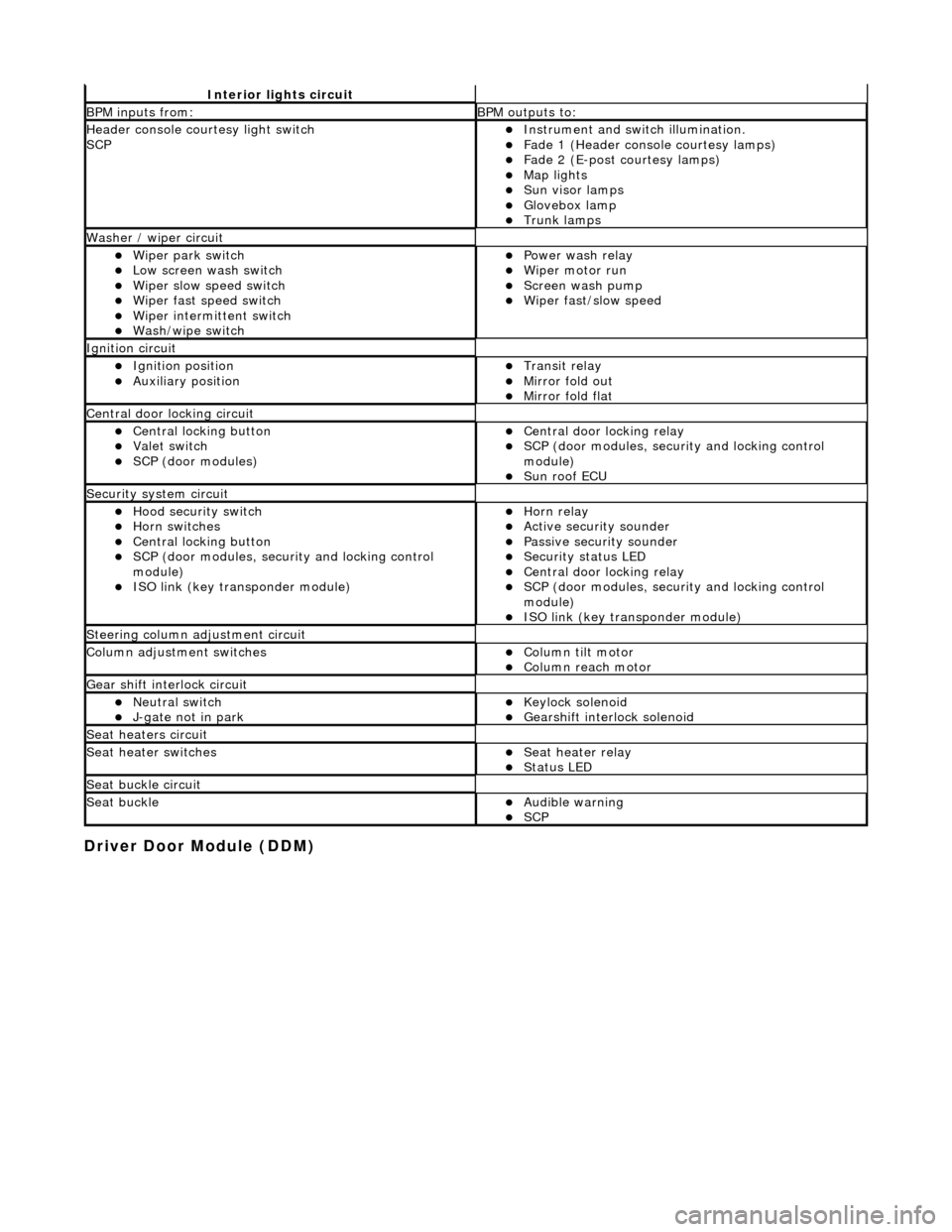
Driver Door Module (DDM)
Interior lights circuit
BPM inputs from: BPM outputs to:
Header console courtesy light switch
SCPпЃ¬Instrument and switch illumination. пЃ¬Fade 1 (Header console courtesy lamps) пЃ¬Fade 2 (E-post courtesy lamps) пЃ¬Map lights пЃ¬Sun visor lamps пЃ¬Glovebox lamp пЃ¬Trunk lamps
Washer / wiper circuit
пЃ¬Wiper park switch пЃ¬Low screen wash switch пЃ¬Wiper slow speed switch пЃ¬Wiper fast speed switch пЃ¬Wiper intermittent switch пЃ¬Wash/wipe switch
пЃ¬Power wash relay пЃ¬Wiper motor run пЃ¬Screen wash pump пЃ¬Wiper fast/slow speed
Ignition circuit
пЃ¬Ignition position пЃ¬Auxiliary position пЃ¬Transit relay пЃ¬Mirror fold out пЃ¬Mirror fold flat
Central door locking circuit
пЃ¬Central locking button пЃ¬Valet switch пЃ¬SCP (door modules)
пЃ¬Central door locking relay пЃ¬SCP (door modules, security and locking control
module)
пЃ¬Sun roof ECU
Security system circuit
пЃ¬Hood security switch пЃ¬Horn switches пЃ¬Central locking button пЃ¬SCP (door modules, security and locking control
module)
пЃ¬ISO link (key transponder module)
пЃ¬Horn relay пЃ¬Active security sounder пЃ¬Passive security sounder пЃ¬Security status LED пЃ¬Central door locking relay пЃ¬SCP (door modules, security and locking control
module)
пЃ¬ISO link (key transponder module)
Steering column adjustment circuit
Column adjustment switchesпЃ¬Column tilt motor пЃ¬Column reach motor
Gear shift interlock circuit
пЃ¬Neutral switch пЃ¬J-gate not in park пЃ¬Keylock solenoid пЃ¬Gearshift interlock solenoid
Seat heaters circuit
Seat heater switchesпЃ¬Seat heater relay пЃ¬Status LED
Seat buckle circuit
Seat buckleпЃ¬Audible warning пЃ¬SCP
Page 2015 of 2490
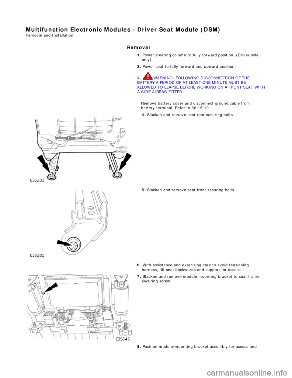
Multifunction Electronic Modules - Driver Seat Module (DSM)
Removal and Installation
Removal
1. Power steering column to fully forward position. (Driver side
only)
2. Power seat to fully forward and upward position.
3. WARNING: FOLLOWING DISCONNECTION OF THE
BATTERY A PERIOD OF AT LEAST ONE MINUTE MUST BE
ALLOWED TO ELAPSE BEFORE WORKING ON A FRONT SEAT WITH
A SIDE AIRBAG FITTED.
Remove battery cover and disc onnect ground cable from
battery terminal. Refer to 86.15.19.
4. Slacken and remove seat rear securing bolts.
5. Slacken and remove seat front securing bolts.
6. With assistance and exercising care to avoid tensioning
harness, tilt seat backwa rds and support for access.
7. Slacken and remove module moun ting bracket to seat frame
securing screw.
8. Position module/mounting bracket assembly for access and
Page 2016 of 2490

Installation
slacken and remove module to bracket securing screws.
9.
Remove seat control module.
1. Disconnect harness multiplugs from module.
2. Withdraw module from seat
1. Position control module at seat and connect harness
multiplugs.
2. Position control module on mounting bracket and fit and
tighten securing screws.
3. Position control module/mountin g bracket assembly on seat
frame and fit and tighten securing screw.
4. Position seat over se curing bolt holes.
5. Fit and tighten seat front securing bolts
6. Fit and tighten seat re ar securing bolts.
7. Connect ground cable to battery terminal and fit battery cover.
Refer to 86.15.15.
8. Return seat to original position.
9. Return steering column to original position.
Page 2021 of 2490
Body System - General Information - Body
Description and Operation
This section covers the following areas of the vehicle body:
Front end body panels
Body closures
Aperture seals
Door seals
Instrument panel, console and radio
Centre console
Handles, locks, latches and mechanisms
Wipers and washers
Glass, frames and mechanisms
Fascia
Fuel filler flap assembly
Sun visors
Seating
Interior trim and ornamentation
Exterior trim and ornamentation
Rear view mirrors
Rear parcel tray
Roof console
Bumpers
Occupant restraints
Sliding roof
Steering column cowl
Underscuttle pad
Front End Body Panels
A false bulkhead together with two insulation covers, are installed between the engine compartment and the BIW front
bulkhead to provide optimum insulation ag ainst noise and heat intrusion. Two plenum braces bolted between the BIW upper toeboards and the plenum further increase bodyshell structural integrity. The plastic ra diator grill and vane block achieve
weight reductions over steel parts and provid e high resistance to front end corrosion.
Page 2239 of 2490
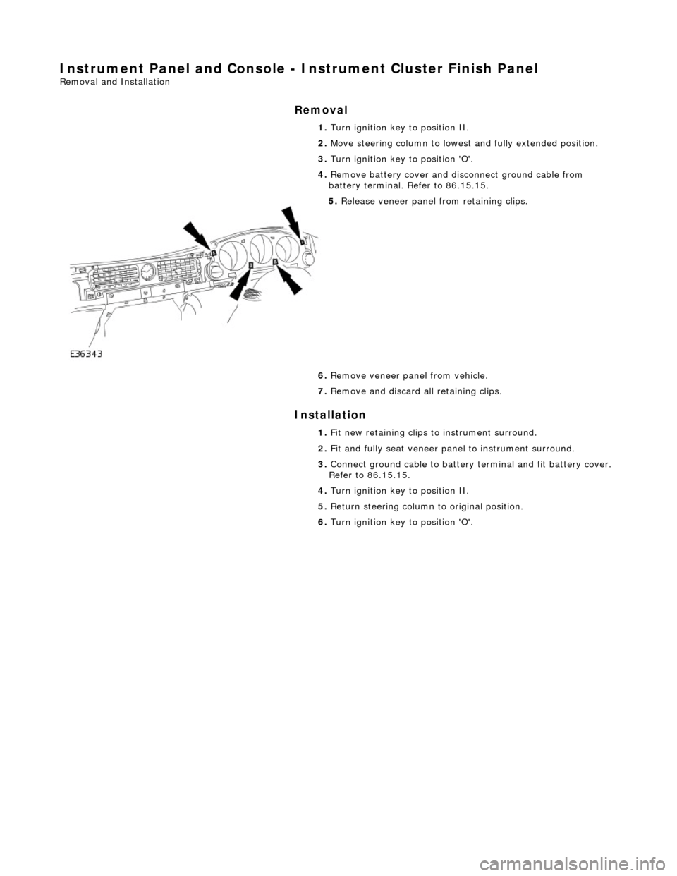
Instrument Panel and Console - Instrument Cluster Finish Panel
Removal and Installation
Removal
Installation
1.
Turn ignition key to position II.
2. Move steering column to lowest and fully extended position.
3. Turn ignition key to position 'O'.
4. Remove battery cover and disc onnect ground cable from
battery terminal. Refer to 86.15.15.
5. Release veneer panel from retaining clips.
6. Remove veneer panel from vehicle.
7. Remove and discard all retaining clips.
1. Fit new retaining clips to instrument surround.
2. Fit and fully seat veneer pa nel to instrument surround.
3. Connect ground cable to battery terminal and fit battery cover.
Refer to 86.15.15.
4. Turn ignition key to position II.
5. Return steering column to original position.
6. Turn ignition key to position 'O'.
Page 2240 of 2490
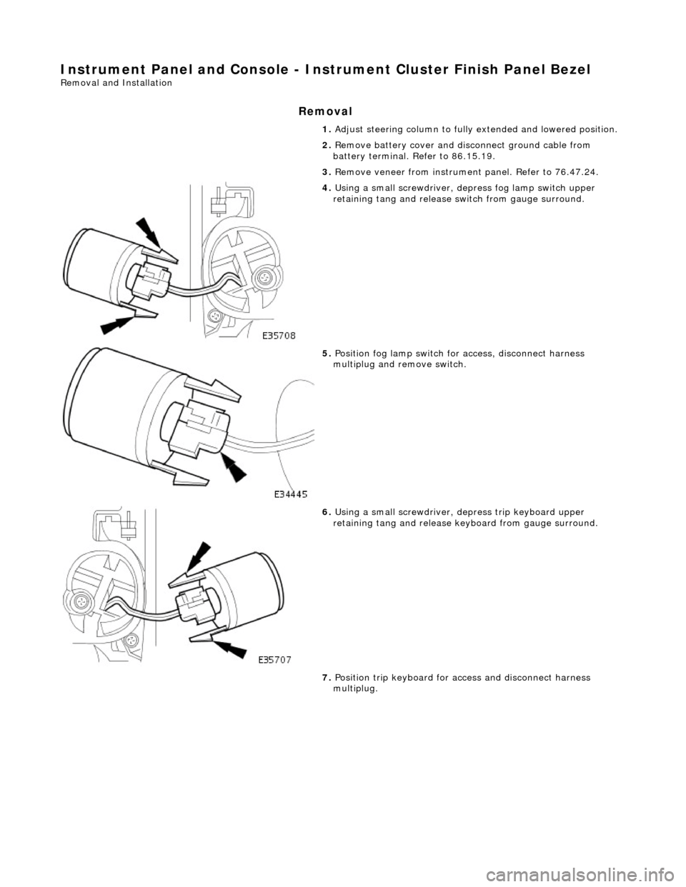
Instrument Panel and Console - Instrument Cluster Finish Panel Bezel
Removal and Installation
Removal
1. Adjust steering column to full y extended and lowered position.
2. Remove battery cover and disc onnect ground cable from
battery terminal. Refer to 86.15.19.
3. Remove veneer from instrument panel. Refer to 76.47.24.
4. Using a small screwdriver, de press fog lamp switch upper
retaining tang and release sw itch from gauge surround.
5. Position fog lamp switch fo r access, disconnect harness
multiplug and remove switch.
6. Using a small screwdriver, depress trip keyboard upper
retaining tang and release ke yboard from gauge surround.
7. Position trip keyboard for ac cess and disconnect harness
multiplug.