Steering column JAGUAR X308 1998 2.G Owner's Guide
[x] Cancel search | Manufacturer: JAGUAR, Model Year: 1998, Model line: X308, Model: JAGUAR X308 1998 2.GPages: 2490, PDF Size: 69.81 MB
Page 514 of 2490

Steering Column Switches -
Torques
Comp
onent
Nm
Swit
ch
gear securing screws
4 -
5
Steeri ng column upper and
l
ower cowl securing screws
1.
5 (
nominal)
Page 515 of 2490
Steering Column Switches - Steering Column Switches
Description an
d Operation
Ig
nition Switch
The k
ey-operated ignition switch is located on the right-hand side of the steering colu
mn and has four positions.
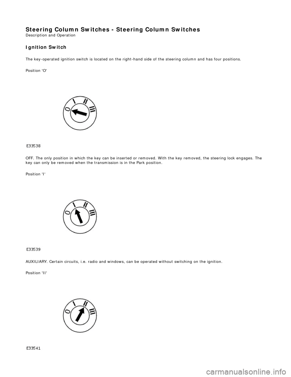
Position 'O'
OFF. The only position in which the key can be inserted or re moved. With the key removed, the steering lock engages. The
key can only be removed when the tran smission is in the Park position.
Position 'I'
AUXILIARY. Certain circuits , i.e. radio and windows, can be operat ed without switching on the ignition.
Position 'II'
Page 516 of 2490
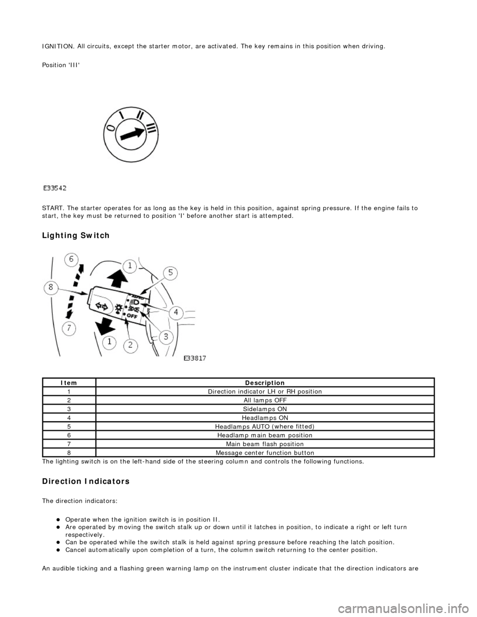
IGNITION.
All circuits, except the star
ter motor, are activated. The key rema ins in this position when driving.
Position 'III'
START. The starter operates for as long as the key is held in this position, ag ainst spring pressure. If the engine fails to
start, the key must be returned to position 'I' befo re another start is attempted.
Lighting Switch
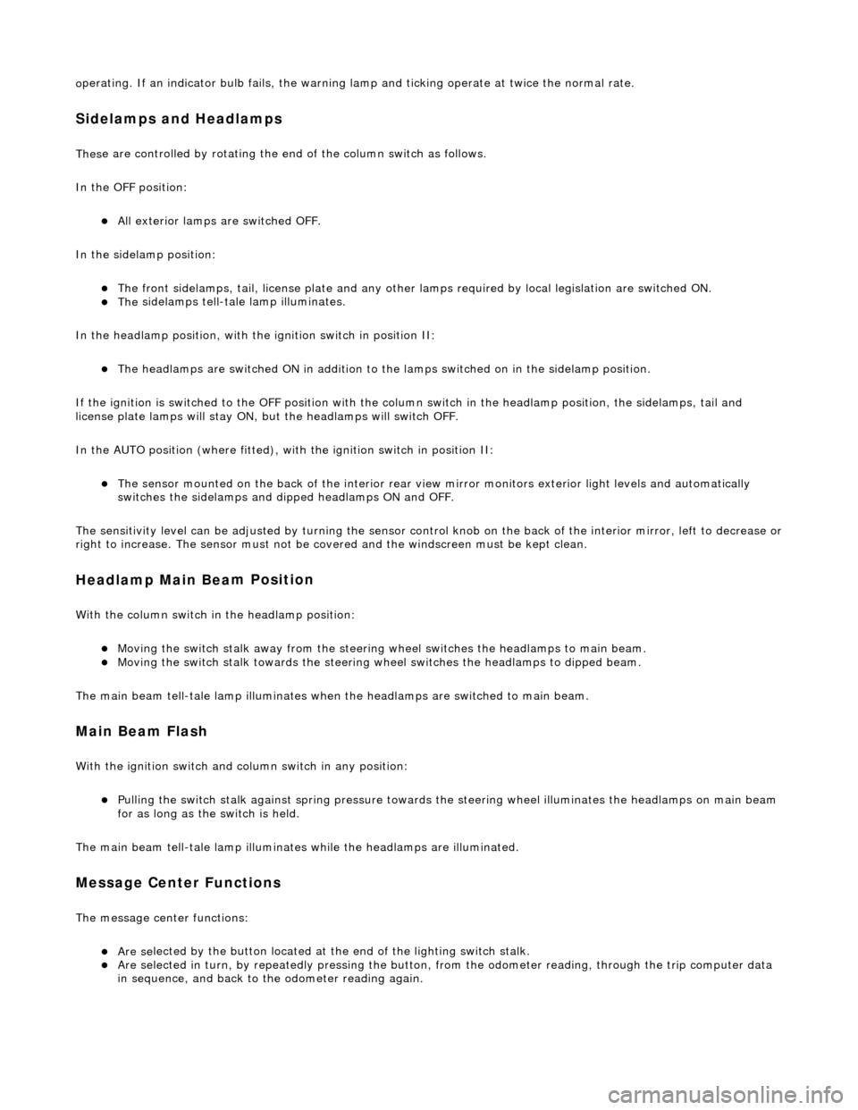
The li
ghting switch is on the left-h
and side of the steering column and controls the following functions.
Direction Indicators
The direction in
dicators:
пЃ¬Operate
when the ignition switch is in position II.
пЃ¬Are operat
ed by movi
ng the switch stalk up or down until it latches in position, to in
dicate a right or left turn
respectively.
пЃ¬Can be o p
erated while the switch stalk is held against
spring pressure before reaching the latch position.
пЃ¬Cancel
automatically upon completion of a turn, the
column switch returning to the center position.
An audible ticking and a flashing green warning lamp on the in strument cluster indicate that the direction indicators are
Ite
m
De
scr
iption
1D
i
rection indicator LH or RH position
2All lamps OFF
3Side
lamps ON
4Headlamps ON
5Headlamps AUT O
(where fitted)
6He
adlam
p main beam position
7Mai
n
beam flash position
8M
e
ssage center function button
Page 517 of 2490
o
perating. If an indicator bulb fails, the warning
lamp and ticking operate at twice the normal rate.
Sidelam
ps and Headlamps
Thes
e are controlled by rotating the end of the column switch as follows.
In the OFF position:
пЃ¬All
exterior lamps are switched OFF.
In the sidelamp position:
пЃ¬The front
sidelamps, tail, license plate and any other la
mps required by local legislation are switched ON.
пЃ¬The
sidelamps tell-tale lamp illuminates.
In the headlamp position, with the ignition switch in position II:
пЃ¬The h
eadlamps are switched ON in addition to the lamps switched on in the sidelamp position.
If the ignition is switched to the OFF position with the column switch in the headlamp position, the sidelamps, tail and
license plate lamps will stay ON, but the headlamps will switch OFF.
In the AUTO position (where fitted), with the ignition switch in position II:
пЃ¬Th
e sensor mounted on the back of the interior rear view
mirror monitors exterior light levels and automatically
switches the sidelamps and di pped headlamps ON and OFF.
The sensitivity level can be adjusted by turn ing the sensor control knob on the back of the interior mirror, left to decrease or
right to increase. The sensor must not be covered and the windscreen must be kept clean.
Headlamp Main Bea
m Position
Wi
th the column switch in
the headlamp position:
пЃ¬Movin
g the switch stalk away fro
m the steering wheel switches the headlamps to main beam.
пЃ¬Movin
g the switch stalk towards the steering wheel switches the headlamps to dipped beam.
The main beam tell-tale lamp illuminates when the headlamps are switched to main beam.
Ma
in Beam Flash
Wi
th the ignition switch and column switch in any position:
пЃ¬Pulling the
switch stalk agains
t spring pressure towards th e steering wheel illuminates the headlamps on main beam
for as long as the switch is held.
The main beam tell-tale lamp illuminates while the headlamps are illuminated.
M
essage Center Functions
T
he message center functions:
пЃ¬Are se
lected by the button located at the end of the lighting switch stalk.
пЃ¬Are se
lected in turn, by repeatedly pressing the button,
from the odometer reading, through the trip computer data
in sequence, and back to th e odometer reading again.
Page 518 of 2490
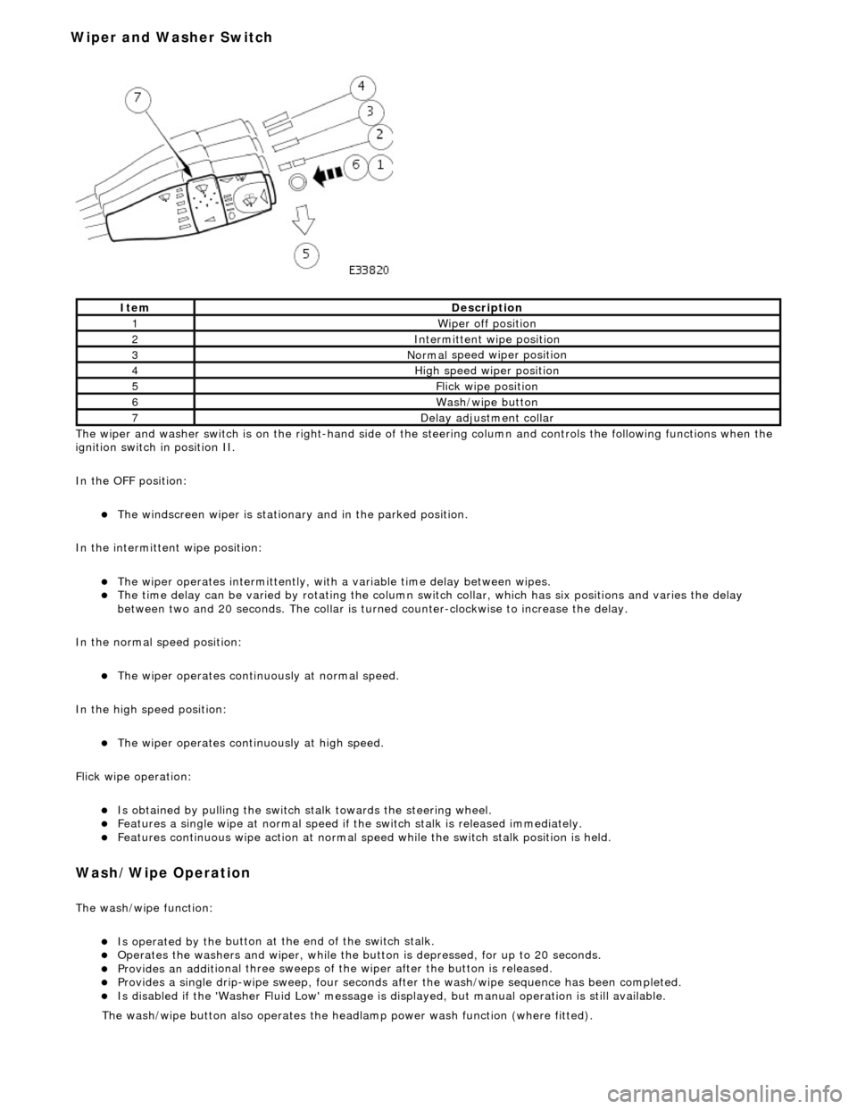
The wiper and washer switch i s
on the righ
t-hand side of the steering column and controls the fo llowing functions when the
ignition switch in position II.
In the OFF position:
пЃ¬The windscreen wiper is stationary and in the parked positio
n.
In the intermittent wipe position:
пЃ¬The wi per ope
rates intermittently, with
a variable time delay between wipes.
пЃ¬The time del
ay can be varied by rotating the column sw
itch collar, which has six positions and varies the delay
between two and 20 seconds. The collar is turned counter-clockwise to increase the delay.
In the normal speed position:
пЃ¬The wiper oper a
tes continuously at normal speed.
In the high speed position:
пЃ¬The wiper ope r
ates continuously at high speed.
Flick wipe operation:
пЃ¬Is obt
ained by pulling the switch
stalk towards the steering wheel.
пЃ¬F
e
atures a single wipe at normal speed if
the switch stalk is released immediately.
пЃ¬Fe
atures continuous wipe action
at normal speed while the swit ch stalk position is held.
Wash/W
ipe Operation
Th
e
wash/wipe function:
пЃ¬Is operat
ed by th
e button at the end of the switch stalk.
пЃ¬Op
erate
s the washers and wiper, while the butt
on is depressed, for up to 20 seconds.
пЃ¬Provides an addit
ional three sweeps of
the wiper after the button is released.
пЃ¬Provid
es a single drip-wipe sweep, four seconds af
ter the wash/wipe sequence has been completed.
пЃ¬Is disabled if the 'Washer Flu
id Low' message is di
splayed, but manual operat ion is still available.
Ite
m
De
scr
iption
1W
i
per off position
2Intermittent
wipe position
3Normal
speed wiper position
4High
speed wiper position
5Flick wipe position
6Wa
sh/wipe button
7D
e
lay adjustment collar
The was
h
/wipe button also operates the head
lamp power wash function (where fitted).
Wiper and Washer Switch
Page 519 of 2490
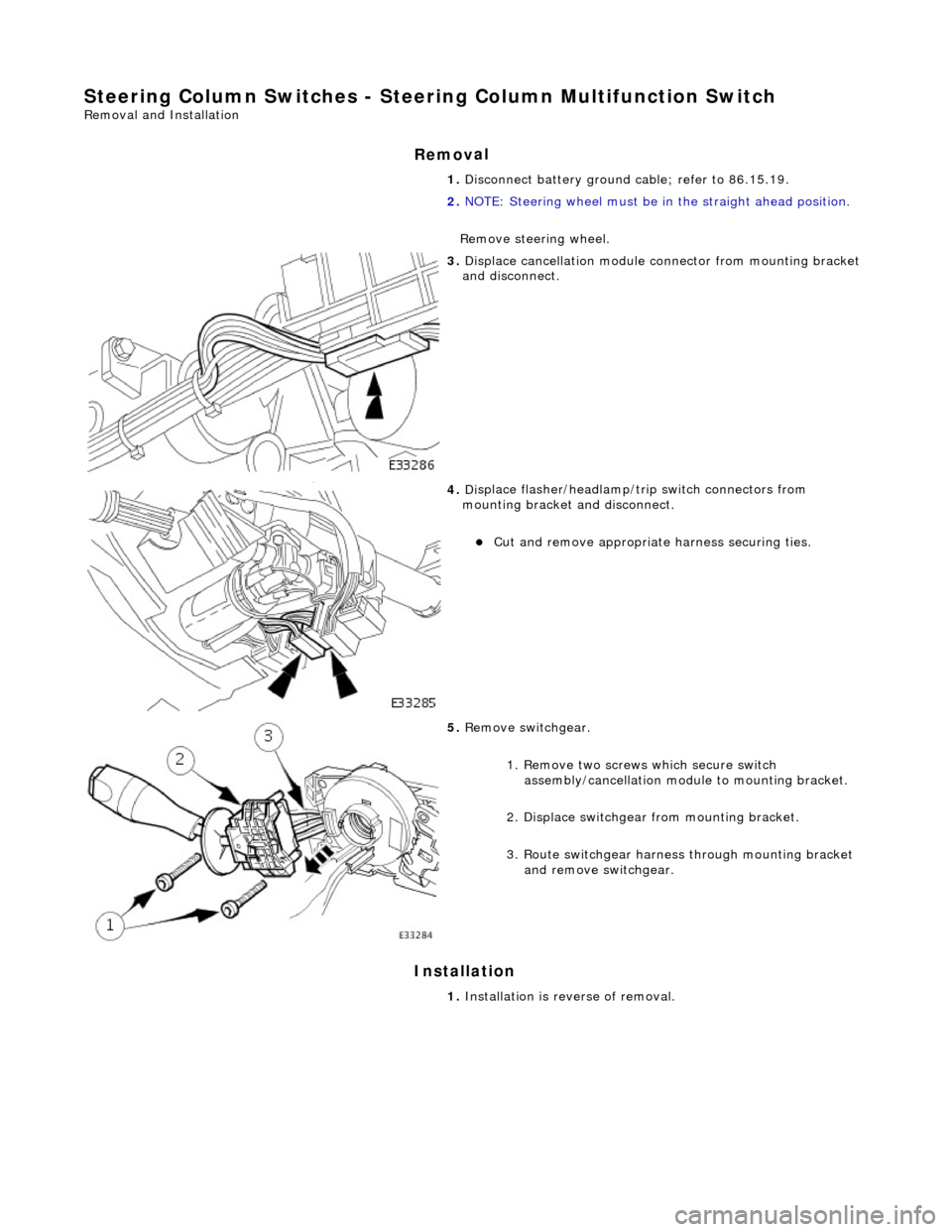
Steering Column Switches - Steering Colu
mn Multifunction Switch
Re
moval and Installation
Remov
al
Installation
1.
D
isconnect battery ground cable; refer to 86.15.19.
2. NOTE: Steering wheel must be in the straight ahead position.
Remove steering wheel.
3. Di
splace cancellation module connector from mounting bracket
and disconnect.
4. Di
splace flasher/headlamp/t
rip switch connectors from
mounting bracket and disconnect.
пЃ¬Cut an
d remove appropriate harness securing ties.
5. Re
move switchgear.
1. Remove two screws which secure switch assembly/cancellation module to mounting bracket.
2. Displace switchgear from mounting bracket.
3. Route switchgear harness through mounting bracket and remove switchgear.
1. Installation is reverse of removal.
Page 1788 of 2490
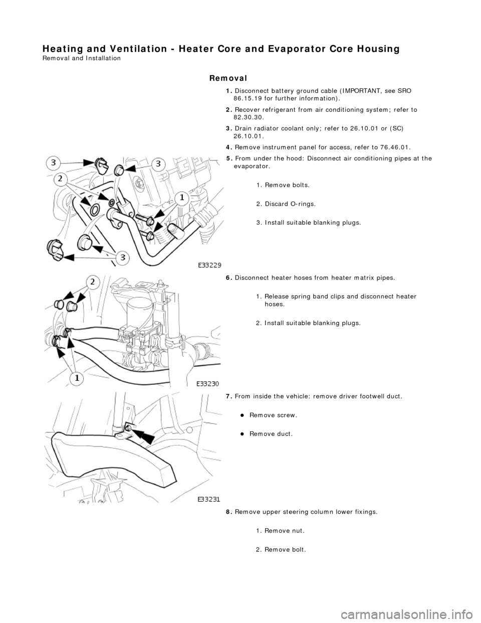
Heating and Ventilation - Heater Core and Evaporator Core Housing
Removal and Installation
Removal
1. Disconnect battery ground cable (IMPORTANT, see SRO
86.15.19 for further information).
2. Recover refrigerant from air co nditioning system; refer to
82.30.30.
3. Drain radiator coolant only; refer to 26.10.01 or (SC)
26.10.01.
4. Remove instrument panel for access, refer to 76.46.01.
5. From under the hood: Disconnect air conditioning pipes at the
evaporator.
1. Remove bolts.
2. Discard O-rings.
3. Install suitable blanking plugs.
6. Disconnect heater hoses from heater matrix pipes.
1. Release spring band clips and disconnect heater hoses.
2. Install suitable blanking plugs.
7. From inside the vehicle: re move driver footwell duct.
пЃ¬Remove screw.
пЃ¬Remove duct.
8. Remove upper steering column lower fixings.
1. Remove nut.
2. Remove bolt.
Page 1789 of 2490
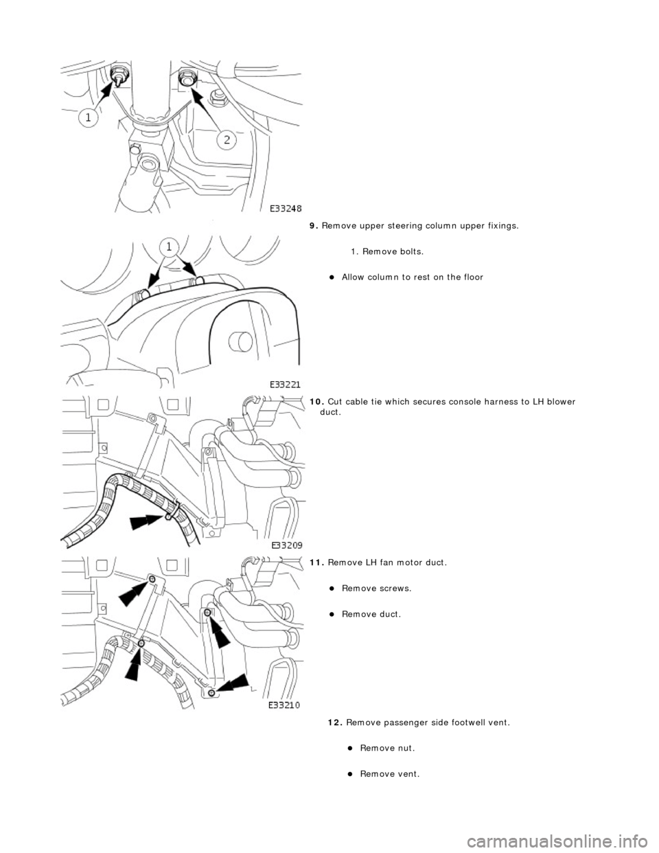
9. Remove upper steering column upper fixings.
1. Remove bolts.
пЃ¬Allow column to rest on the floor
10. Cut cable tie which secures console harness to LH blower
duct.
11. Remove LH fan motor duct.
пЃ¬Remove screws.
пЃ¬Remove duct.
12. Remove passenger si de footwell vent.
пЃ¬Remove nut.
пЃ¬Remove vent.
Page 1796 of 2490
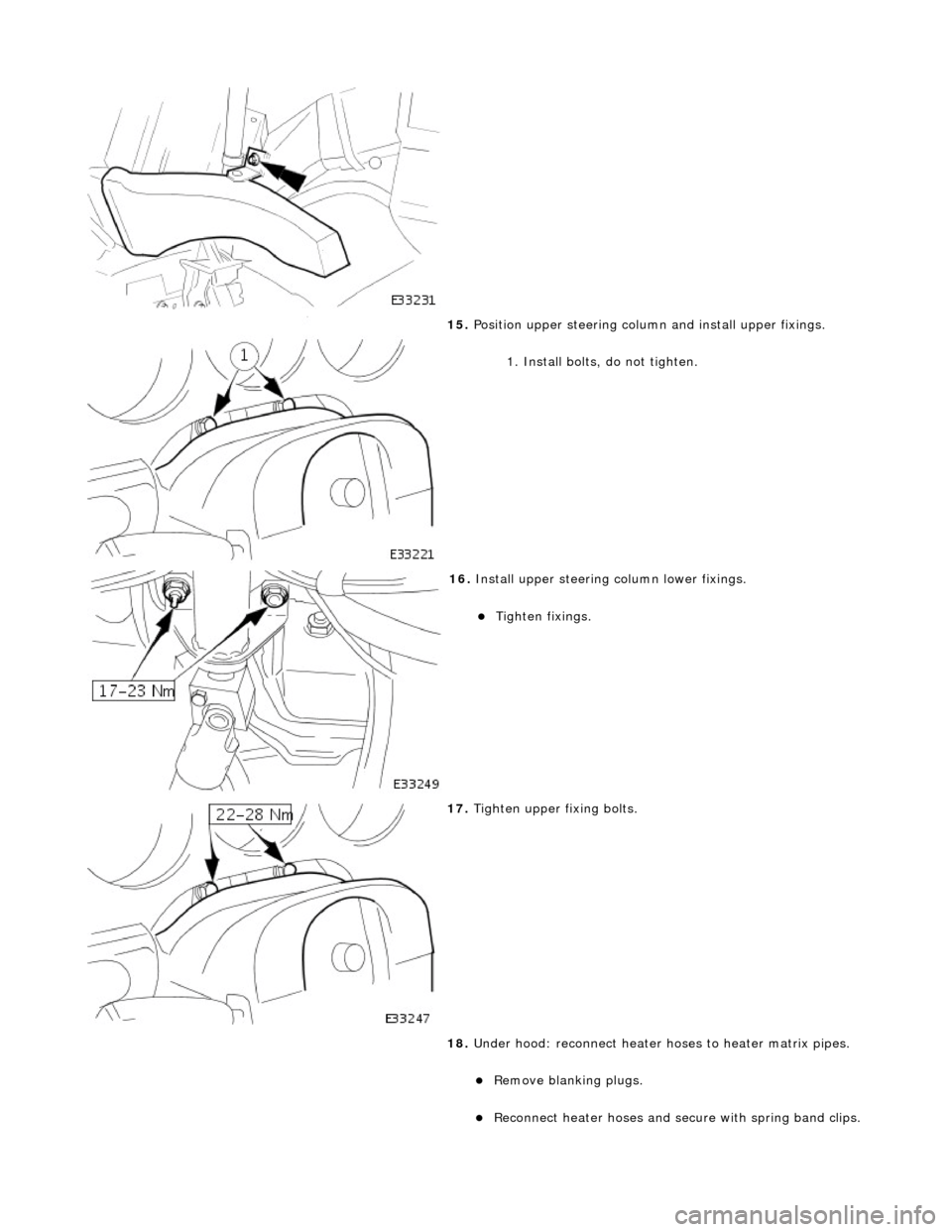
15. Position upper steering column and install upper fixings.
1. Install bolts, do not tighten.
16. Install upper steering column lower fixings.
пЃ¬Tighten fixings.
17. Tighten upper fi xing bolts.
18. Under hood: reconnect heater ho ses to heater matrix pipes.
пЃ¬Remove blanking plugs.
пЃ¬Reconnect heater hoses and secure with spring band clips.
Page 1831 of 2490
other sensors. This feature prevents the effects of sudden changes in air outlet temperatures due to factors such as:
пЃ¬Recirculating air from the engine cooling pack at low vehicle speeds пЃ¬Sudden changes in ambient temperature пЃ¬The effects of water splash
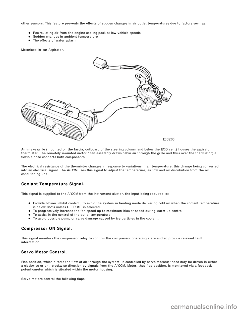
Motorised In-car Aspirator.
An intake grille (mounted on the fascia , outboard of the steering column and below the EOD vent) houses the aspirator
thermister. The remotely mounted motor / fan assembly draws ca bin air through the grille and thus over the thermistor; a
flexible hose connects both components.
The electrical resistance of the thermistor changes in response to variations in air temperatur e, this change being converted
into an electrical signal. The A/CCM uses this signal to adjust the temperature, airflow and air distribution from the air
conditioning unit.
Coolant Temperature Signal.
This signal is supplied to the A/CCM from the instrument cluster, the input being required to:
пЃ¬Provide blower inhibit control , to avoid the system in heat ing mode delivering cold air when the coolant temperature is below 35В°C unless DEFROST is selected. пЃ¬To progressively increase the fan speed up to maximum blower speed during warm up control. пЃ¬To assist in the control of the outlet temperature. пЃ¬To avoid possible pump or valve damage ca used by ice particles in the coolant.
Compressor ON Signal.
This signal monitors the compressor relay to confirm the compressor operating state and so provide relevant fault
information.
Servo Motor Control.
Flap position, which directs the flow of air through the system, is controlled by servo motors; these may be driven in either
a clockwise or anti-clockwise direction by signals from the A/ CCM. Motor, thus flap position, is monitored via a feedback
potentiometer which is situated within the motor housing.
Servo motors control the following flaps: