steering wheel JAGUAR X308 1998 2.G Repair Manual
[x] Cancel search | Manufacturer: JAGUAR, Model Year: 1998, Model line: X308, Model: JAGUAR X308 1998 2.GPages: 2490, PDF Size: 69.81 MB
Page 505 of 2490
Steering Column - Steering Column
Description an
d Operation
Stee
ring Wheel
T
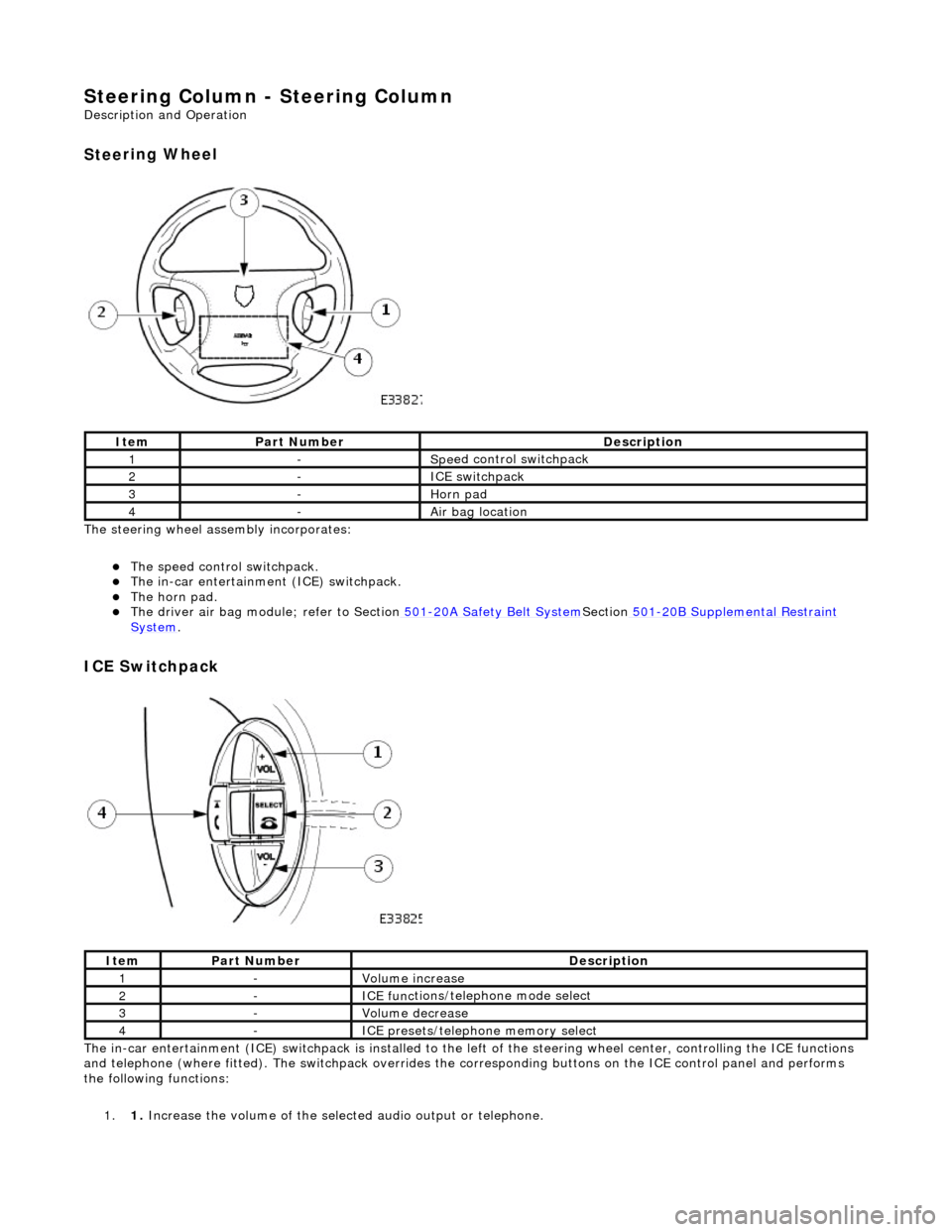
he steering wheel assembly incorporates:
The s
peed control switchpack.
The i
n-car entertainment (ICE) switchpack.
The h
orn pad.
The driver ai
r bag module; refer to Section
501
-20A Safety Belt
System
Sectio
n
501
-2
0B Supplemental Restraint
Sy
stem
.
I
CE Switchpack
The
in-car entertainment (ICE) switchpack is installed to the le
ft of the steering wheel center, controlling the ICE functions
and telephone (where fitted). The switchpack overrides the corresponding bu ttons on the ICE control panel and performs
the following functions:
1. 1. Increase the volume of the select ed audio output or telephone.
It
em
Par
t Number
De
scription
1-Spe
ed control switchpack
2-I
CE switchpack
3-Horn pad
4-Air bag lo
cation
It
em
Par
t Number
De
scription
1-Vol
ume increase
2-ICE func
tions/teleph
one mode select
3-Volum
e decrease
4-ICE pres
ets/telephone memory select
Page 506 of 2490
2.2. Press and rel e
ase to cycle through radio FM, radio AM,
tape cassette, or CD player. Press and hold for two
seconds to select telephone mode.
3. 3. Decrease the volume of the select ed audio output or telephone.
4. 4. Press and release to select the next pr eset radio station, or the next track on tape or CD. Press and hold for two
seconds to select the next radio station on the waveband upwards, or the next CD loaded in the player, or to
change the side of tape. When in te lephone mode, press and release to scroll up to the next memory location.
Press and hold for two seconds to send and end a call.
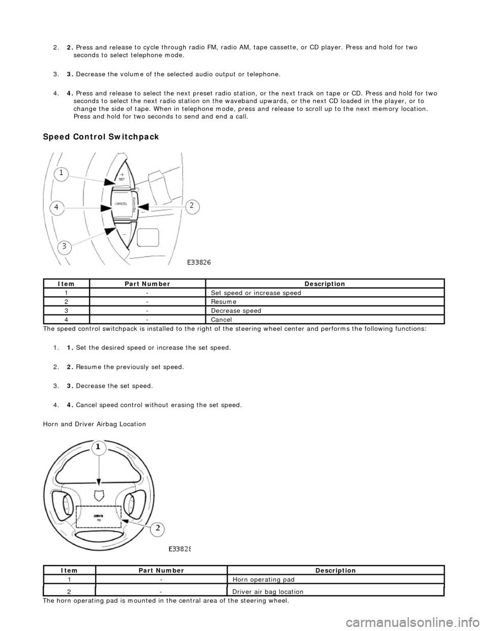
Speed Control Switchpa ck
The s p
eed control switchpack is installed to the right of th
e steering wheel center and performs the following functions:
1. 1. Set the desired speed or increase the set speed.
2. 2. Resume the previously set speed.
3. 3. Decrease the set speed.
4. 4. Cancel speed control without erasing the set speed.
Horn and Driver Airbag Location
Ite
m
Par
t
Number
De
scr
iption
1-Se
t
speed or increase speed
2-Re
sum
e
3-De
creas
e speed
4-Cancel
Ite
m
Part
Number
Descr
iption
1-Horn operatin
g pad
The ho
rn operating pad is mounted in the central area of the steering wheel.
2-Driver air bag location
Page 507 of 2490
The driver air bag is moun
ted below the horn operat
ing pad area, adjacent to the steering wheel hub.
For air bag safety and service information, refer to Section 501
-20A Safety Belt
System
Sectio
n
501
-2
0B Supplemental
Re
straint System
.
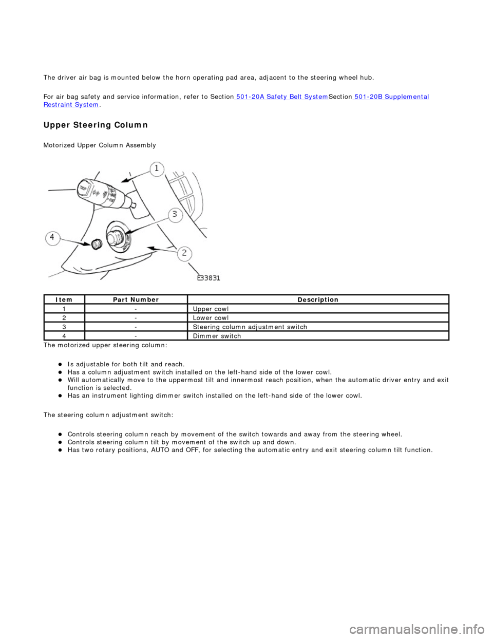
Upper Steering Column
Motorized Upper Colu
mn Assembly
The motorized upper steering column:
Is adjustable for both til
t and reach.
Has a col
umn adjustment switch installed on
the left-hand side of the lower cowl.
W
ill automatically move to the uppermost tilt and innermost reach position, when the automatic driver entry and exit
function is selected.
Has an instrument li
ghti
ng dimmer switch installed on the left-hand side of the lower cowl.
The steering column adjustment switch:
Controls steeri
ng column reach by
movement of the switch towards an d away from the steering wheel.
Controls steeri
ng column tilt by mo
vement of the switch up and down.
Has two
rotary positions, AUTO and OFF, for selecting the
automatic entry and exit steering column tilt function.
It
em
Par
t Number
De
scription
1-Upper
cowl
2-Lower cowl
3-Ste
ering column adjustment switch
4-Di
mmer switch
Page 508 of 2490
The te
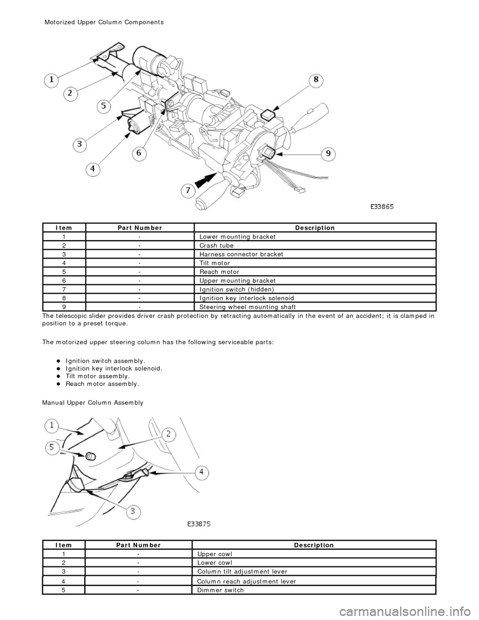
lescopic slider provides driver crash
protection by retracting automatically in the event of an accident; it is clamped in
position to a preset torque.
The motorized upper steering column has the following serviceable parts:
Igniti
on switch assembly.
Igni
ti
on key interlock solenoid.
Ti
lt
motor assembly.
Reach motor assembly.
Manu al Upper Column Assembly
Ite
m
Par
t
Number
De
scr
iption
1-L
o
wer mounting bracket
2-Crash tube
3-Harnes
s c
onnector bracket
4-Tilt motor
5-Reach m
otor
6-Upper
moun
ting bracket
7-Ignition switc
h
(hidden)
8-Igni
ti
on key interlock solenoid
9-S
t
eering wheel mounting shaft
It
e
m
Par
t
Number
De
scr
iption
1-Upper
cowl
2-Lower cowl
3-Colu
mn tilt adjustment lever
4-Col
u
mn reach adjustment lever
5-Di
mm
er switch
Motorized Upper Co
lumn Components
Page 509 of 2490
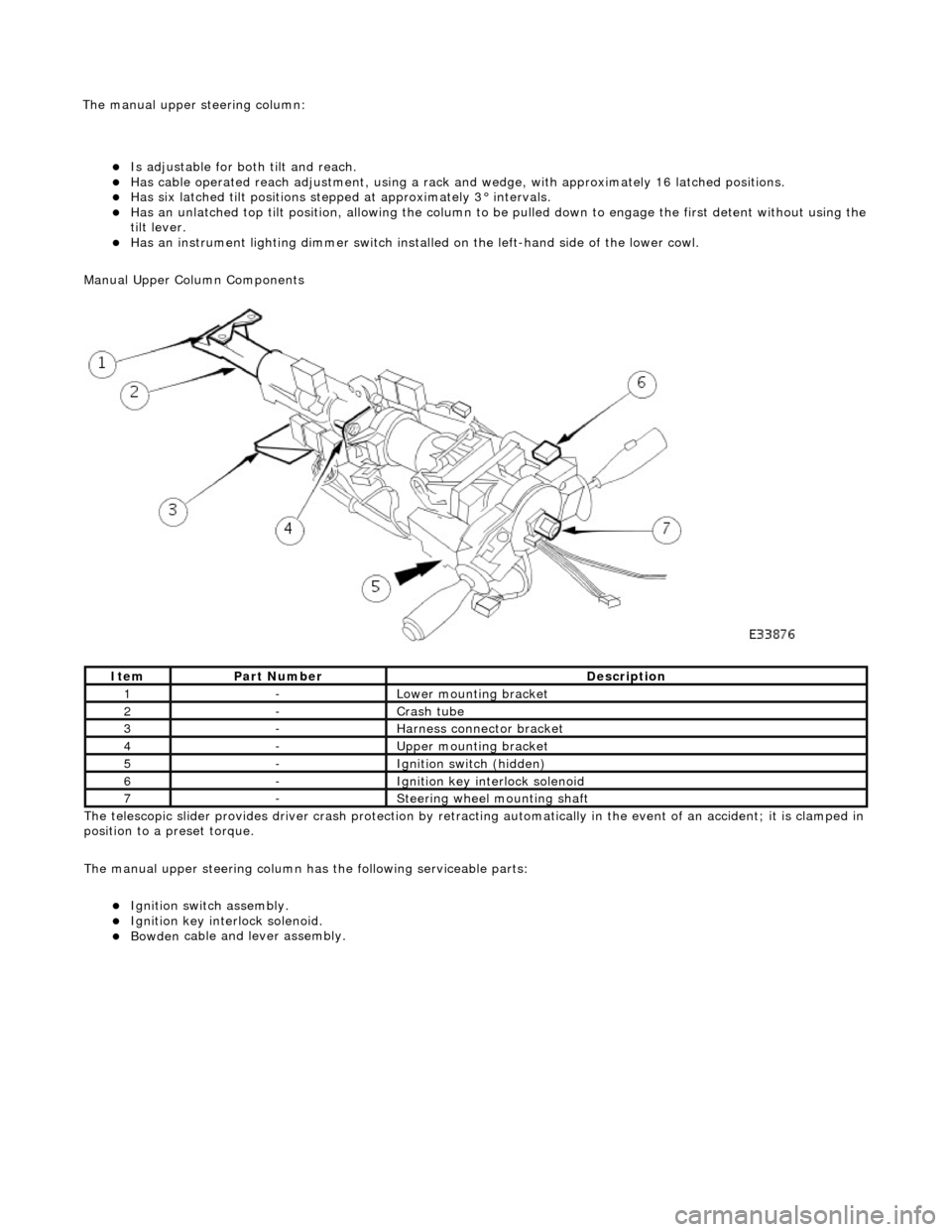
Is adjustable for both til
t and reach.
Has ca
ble operated reach adjustment, using a rack an
d wedge, with approximately 16 latched positions.
Has si
x latched tilt positions steppe
d at approximately 3° intervals.
Has an u
nlatched top tilt position, allowing the column to be
pulled down to engage the first detent without using the
tilt lever.
Has an instrument li
ghti
ng dimmer switch installed on the left-hand side of the lower cowl.
Manual Upper Column Components
The telescopic slider provides driver crash protection by retracting automatically in the event of an accident; it is clamped in
position to a preset torque.
The manual upper steering column has the following serviceable parts:
Igni
tion switch assembly.
Igni
tion key interlock solenoid.
Bowden
cable and lever assembly.
It
em
Par
t Number
De
scription
1-L
ower mounting bracket
2-Crash tube
3-Harnes
s connector bracket
4-Upper
mounting bracket
5-Ignition switc
h (hidden)
6-Igni
tion key interlock solenoid
7-S
teering wheel mounting shaft
The manu
al upper
steering column:
Page 517 of 2490
o
perating. If an indicator bulb fails, the warning
lamp and ticking operate at twice the normal rate.
Sidelam
ps and Headlamps
Thes
e are controlled by rotating the end of the column switch as follows.
In the OFF position:
All
exterior lamps are switched OFF.
In the sidelamp position:
The front
sidelamps, tail, license plate and any other la
mps required by local legislation are switched ON.
The
sidelamps tell-tale lamp illuminates.
In the headlamp position, with the ignition switch in position II:
The h
eadlamps are switched ON in addition to the lamps switched on in the sidelamp position.
If the ignition is switched to the OFF position with the column switch in the headlamp position, the sidelamps, tail and
license plate lamps will stay ON, but the headlamps will switch OFF.
In the AUTO position (where fitted), with the ignition switch in position II:
Th
e sensor mounted on the back of the interior rear view
mirror monitors exterior light levels and automatically
switches the sidelamps and di pped headlamps ON and OFF.
The sensitivity level can be adjusted by turn ing the sensor control knob on the back of the interior mirror, left to decrease or
right to increase. The sensor must not be covered and the windscreen must be kept clean.
Headlamp Main Bea
m Position
Wi
th the column switch in
the headlamp position:
Movin
g the switch stalk away fro
m the steering wheel switches the headlamps to main beam.
Movin
g the switch stalk towards the steering wheel switches the headlamps to dipped beam.
The main beam tell-tale lamp illuminates when the headlamps are switched to main beam.
Ma
in Beam Flash
Wi
th the ignition switch and column switch in any position:
Pulling the
switch stalk agains
t spring pressure towards th e steering wheel illuminates the headlamps on main beam
for as long as the switch is held.
The main beam tell-tale lamp illuminates while the headlamps are illuminated.
M
essage Center Functions
T
he message center functions:
Are se
lected by the button located at the end of the lighting switch stalk.
Are se
lected in turn, by repeatedly pressing the button,
from the odometer reading, through the trip computer data
in sequence, and back to th e odometer reading again.
Page 518 of 2490
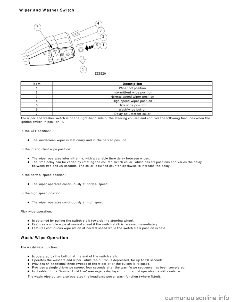
The wiper and washer switch i s
on the righ
t-hand side of the steering column and controls the fo llowing functions when the
ignition switch in position II.
In the OFF position:
The windscreen wiper is stationary and in the parked positio
n.
In the intermittent wipe position:
The wi per ope
rates intermittently, with
a variable time delay between wipes.
The time del
ay can be varied by rotating the column sw
itch collar, which has six positions and varies the delay
between two and 20 seconds. The collar is turned counter-clockwise to increase the delay.
In the normal speed position:
The wiper oper a
tes continuously at normal speed.
In the high speed position:
The wiper ope r
ates continuously at high speed.
Flick wipe operation:
Is obt
ained by pulling the switch
stalk towards the steering wheel.
F
e
atures a single wipe at normal speed if
the switch stalk is released immediately.
Fe
atures continuous wipe action
at normal speed while the swit ch stalk position is held.
Wash/W
ipe Operation
Th
e
wash/wipe function:
Is operat
ed by th
e button at the end of the switch stalk.
Op
erate
s the washers and wiper, while the butt
on is depressed, for up to 20 seconds.
Provides an addit
ional three sweeps of
the wiper after the button is released.
Provid
es a single drip-wipe sweep, four seconds af
ter the wash/wipe sequence has been completed.
Is disabled if the 'Washer Flu
id Low' message is di
splayed, but manual operat ion is still available.
Ite
m
De
scr
iption
1W
i
per off position
2Intermittent
wipe position
3Normal
speed wiper position
4High
speed wiper position
5Flick wipe position
6Wa
sh/wipe button
7D
e
lay adjustment collar
The was
h
/wipe button also operates the head
lamp power wash function (where fitted).
Wiper and Washer Switch
Page 519 of 2490
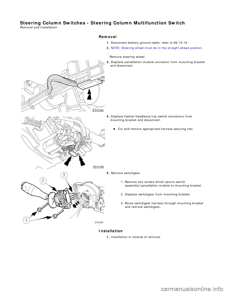
Steering Column Switches - Steering Colu
mn Multifunction Switch
Re
moval and Installation
Remov
al
Installation
1.
D
isconnect battery ground cable; refer to 86.15.19.
2. NOTE: Steering wheel must be in the straight ahead position.
Remove steering wheel.
3. Di
splace cancellation module connector from mounting bracket
and disconnect.
4. Di
splace flasher/headlamp/t
rip switch connectors from
mounting bracket and disconnect.
Cut an
d remove appropriate harness securing ties.
5. Re
move switchgear.
1. Remove two screws which secure switch assembly/cancellation module to mounting bracket.
2. Displace switchgear from mounting bracket.
3. Route switchgear harness through mounting bracket and remove switchgear.
1. Installation is reverse of removal.
Page 1201 of 2490

leak
/blockage
EVAP valve failure
P0444Evaporati
ve emissions system
(EVAP) valve circuit open circuit
EVAP t
o ECM drive circuit open
circuit or high resistance
EVAP failu
re
F
or evaporative emissions pinpoint
tests,
REFER to Section 303
-1
3 Evaporative
Emiss
ions
.
P0445Evaporati
ve emissions system
(EVAP) valve circuit short circuit
E
VAP to ECM drive circuit short
circuit to ground
EVAP failu
re
F
or evaporative emissions pinpoint
tests,
REFER to Section 303
-1
3 Evaporative
Emiss
ions
.
P0447Cani
ster close valve (CCV) circuit
open circuit
CCV to ECM
drive circuit open
circuit, high resi stance or short
circuit to ground
EVAP failu
re
F
or evaporative emissions pinpoint
tests,
REFER to Section 303
-1
3 Evaporative
Emiss
ions
.
P0448Cani
ster close valve (CCV) circuit
short circuit
CCV to
ECM drive circuit short
circuit to high voltage
CCV failure
F
or evaporative emissions pinpoint
tests,
REFER to Section 303
-1
3 Evaporative
Emiss
ions
.
P0452F
uel tank pressure (FTP) sensor
circuit low voltage
FTP
sensor disconnected
FTP
sensor to ECM sense circuit
open circuit or short circuit to
ground
FTP sen
sor to ECM power supply
circuit open circuit or short circuit
to ground
F
TP sensor failure
F
or evaporative emissions pinpoint
tests,
REFER to Section 303
-1
3 Evaporative
Emiss
ions
.
P0453F
uel tank pressure (FTP) sensor
circuit high voltage
FTP
sensor to ECM signal ground
circuit open circuit
F
TP sensor to ECM wiring (supply,
sense, signal, ground) short circuit
to each other
FTP
sensor to ECM sense circuit
short circuit to high voltage
F
TP sensor failure
F
or evaporative emissions pinpoint
tests,
REFER to Section 303
-1
3 Evaporative
Emiss
ions
.
P0460Fue
l level sense signal
performance
Fue
l level sensor
to instrument
cluster circuits in termittent short or
open circuit
F
uel level sensor failure
Instrument cluster
faul
t (incorrect
fuel level data)
F
or fuel level sensor
circuit tests,
REFER to Section 303
-04
Fuel
Charging and Con
trols
.
P0506Idl
e rpm lower than expected
Ai
r intake blockage
Acce
ssory drive overload
(defective/siezed component)
Thr
ottle valve stuck closed
Throttl
e assembly failure
Chec
k the air intake system.
REFER to Section 303
-1
2 Intake Air
Distribu
tion and Filtering
.
Check t
he accessory drive
components,
REFER to Section 303
-0
5 Accessory
Dr
ive
.
F
or throttle body information,
REFER to Section 303
-04
Fuel
Charging and Con
trols
.
P0507Idle rpm
higher than expected
Inta
ke air leak between MAF
sensor and throttle
Inta
ke air leak between throttle
and engine
Engine
breather leak
Cruis
e (speed) control vacuum
failure
Thr
ottle valve stuck open
Throttl
e assembly failure
Chec
k the air intake system.
REFER to Section 303
-1
2 Intake Air
Distribu
tion and Filtering
.
Chec
k the engine breather system,
REFER to Section 303
-08
Engine
Emissi
on Control
.
F
or cruise (speed) control information,
REFER to Section 310
-03
Speed
Control.
F
or throttle body information,
REFER to Section 303
-04
Fuel
Charging and Con
trols
.
P0560Vehicle voltage
malfunction
ECM battery
power supply open
circuit, high resistance
F
or ECM power supply circuit tests,
GO to Pinpoint Test AD.
.
P0566Cruise (speed) contr
ol
CANCEL
switch ON fault
Cru
ise (speed) control switches
internal steering wheel short circuit
to ground
For cru
ise (speed) control circuit tests,
REFER to Section 310
-03
Speed
Page 1202 of 2490

St
eering wheel cassette reel short
circuit to ground
Cassette reel to ECM c
ircuit short
circuit to ground
CANC EL
switch failure (stuck ON)
Control.
P0567Cruise (speed) contr
o
l
RESUME
switch ON fault
Cru i
se (speed) control switches
internal steering wheel short circuit
to ground
S t
eering wheel cassette reel short
circuit to ground
Cassette reel to ECM c
ircuit short
circuit to ground
RESUME s
witch failure (stuck ON)
For cru
i
se (speed) control circuit tests,
REFER to Section 310
-03 Sp
eed
Control.
P0568Cru
i
se (speed) control switch
ground malfunction
Cru i
se (speed) control switches
internal steering wheel open circuit
St
eering wheel cassette reel open
circuit or high resistance
Cassette reel to ECM ci
rcuit
ACCEL/DECEL open circuit or high
resistance
ACC E
L/DECEL
switch failure
For crui
se (speed) control circuit tests,
REFER to Section 310
-03 Sp
eed
Control.
P0569Cruise (speed) contr
o
l
DECEL/SET (SET-) switch ON
fault
Cru i
se (speed) control switches
internal steering wheel short circuit
to ground
S t
eering wheel cassette reel short
circuit to ground
Cassette reel to ECM c
ircuit short
circuit to ground
DECE
L/SET
switch failure (stuck
ON)
For cru i
se (speed) control circuit tests,
REFER to Section 310
-03 Sp
eed
Control.
P0570Cruise (speed) contro
l
ACCEL/SET (SET+) switch ON
fault
Crui
se (speed) control switches
internal steering wheel short circuit
to ground
S t
eering wheel cassette reel short
circuit to ground
Cassette reel to ECM c
ircuit short
circuit to ground
ACC E
L/SET
switch failure (stuck
ON)
For crui
se (speed) control circuit tests,
REFER to Section 310
-03 Sp
eed
Control.
P0603ECM dat
a
corrupted
ECM failu
r
e
Contact deal
er techni
cal support for
advice on possible ECM failure.
P1000 Sy
stem checks not complete since
last memory clear
O B
D diagnostic monitors have not
completed
Carr y out comprehensi
ve component
monitor drive cycle. Refer to the DTC
section of JTIS.
P1104Mass ai r fl
ow (MAF) sensor ground
malfunction
MAF sensor to EC
M reference
ground circuit open circuit, short
circuit to high voltage, high
resistance
MAF s
ensor to ECM sensing circuit
open circuit
MAF sensor fai
lure
For MAF
se
nsor circuit tests,GO to
Pinpoint Test A.
.
P1111Syst
em checks complete since last
memory clear
O B
D diagnostic monitors have completed
N
o
action necessary.
P1112In
t
ake air temperature (IAT)
sensor 2 sense circuit high voltage
(low charge air temperature)
IAT sensor 2 di sconnect
ed
IAT sensor 2
to ECM sensing circuit
high resistance, open circuit or
short circuit to high voltage
IAT se nsor 2 failure
F
or IAT sensor
2 circuit tests,GO to
Pinpoint Test Q.
.
P1113Int
ake air temperature (IAT)
sensor 2 sense circuit low voltage
(high charge air temperature)
Supercharger interco
oler failure
IAT se
nsor 2
to ECM sensing circuit
short circuit to ground
IAT se nsor 2 failure
F
or IAT sensor
2 circuit tests,GO to
Pinpoint Test Q.
.
P1121Accele
rator pedal position (APP)
sensor circuit 'A'
range/performance
A P
P sensor to ECM sense circuit
'A' (sensor pin 5) open circuit,
short circuit or high resistance
Sensor power su pply fault
Sensor r
e
ference ground fault
APP s
e
nsor failure
For APP
sen
sor circuit tests,GO to
Pinpoint Test R.
, andGO to Pinpoint
Test S.
.