transmission JAGUAR X308 1998 2.G Repair Manual
[x] Cancel search | Manufacturer: JAGUAR, Model Year: 1998, Model line: X308, Model: JAGUAR X308 1998 2.GPages: 2490, PDF Size: 69.81 MB
Page 920 of 2490
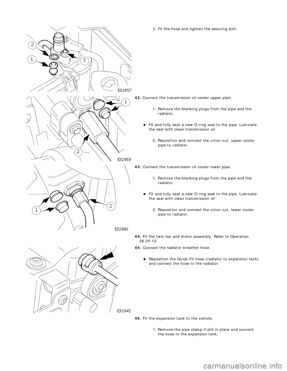
3.
Fit the hose and tighten the securing bolt.
42 . Conne
ct the transmission
oil cooler upper pipe.
1. Remove the blanking plugs from the pipe and the radiator.
пЃ¬Fit and
fully seat a new O-ring
seal to the pipe. Lubricate
the seal with clean transmission oil
2. Reposition and connect the union nut, upper cooler pipe to radiator.
43 . Conne
ct the transmission oil cooler lower pipe.
1. Remove the blanking plugs from the pipe and the radiator.
пЃ¬Fit and
fully seat a new O-ring
seal to the pipe. Lubricate
the seal with clean transmission oil
2. Reposition and connect the union nut, lower cooler
pipe to radiator.
44. Fit the twin fan and motor assembly. Refer to Operation
26.25.12.
45 . Connect
the radiator breather hose.
пЃ¬Re
po
sition the Quick-Fit hose (radiator to expansion tank)
and connect the hose to the radiator.
46. Fit the expansion tank to the vehicle.
1. Remove the pipe clamp if still in place and connect
the hose to the expansion tank.
Page 923 of 2490
be 'hun
g up' within the engine because it is not up to operating
temperature.
Should the oil level subsequently be topped-up, the level could
become too high, causing oil burning.
Typically, 0.875L is hung up.
Refill the engine with the correct specification engine oil.
58. Refill the automatic transmission. Refer to Section 307-01A,
Operation 44.24. 02.
59. Refill and bleed the power stee ring system. Refer to Section
211-02 General Procedures.
60. Repressurise the air conditioni ng system. Refer to Operation
82.30.30 and note all Wa rnings and Cautions.
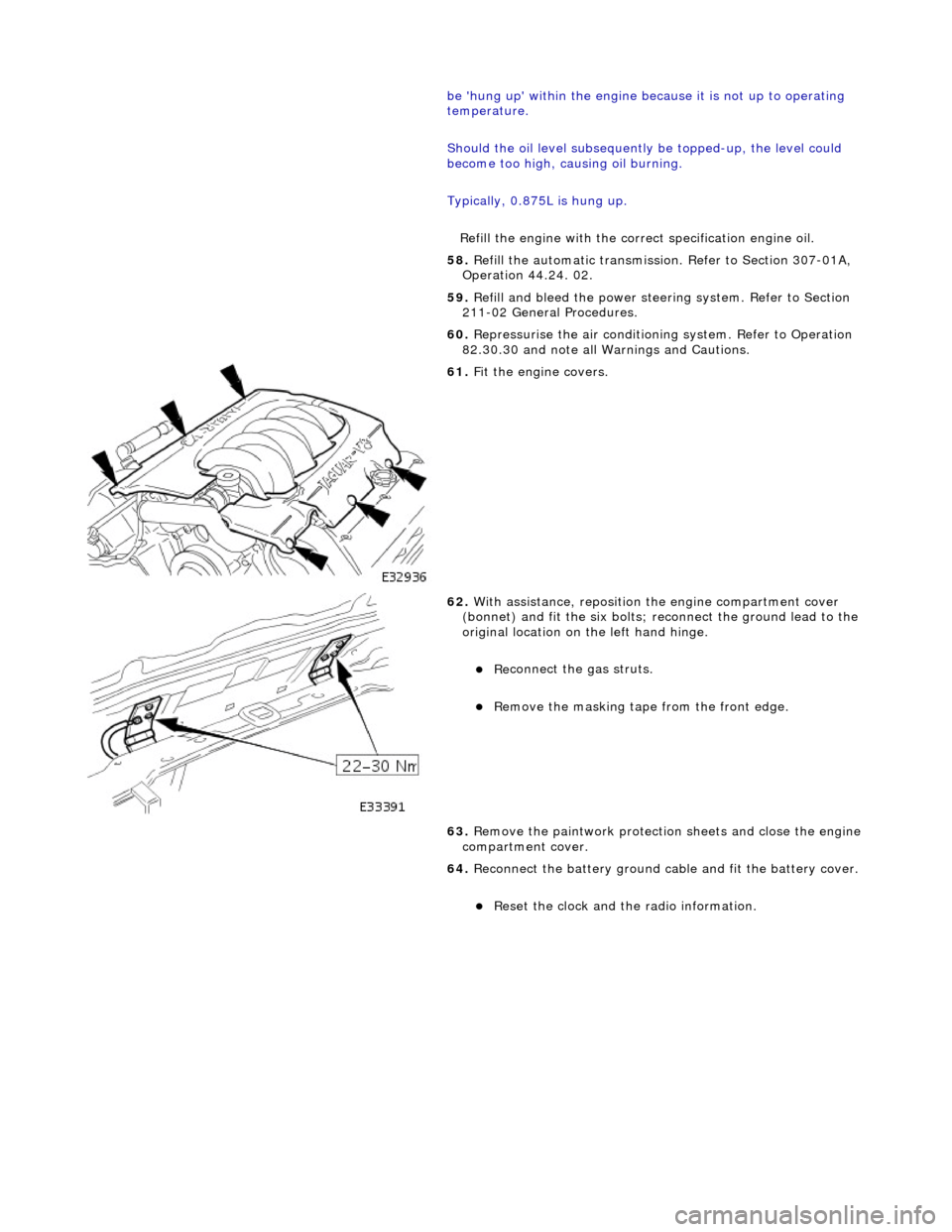
61
.
Fit the engine covers.
62
.
With assistance, reposition the engine compartment cover
(bonnet) and fit the si x bolts; reconnect the ground lead to the
original location on the left hand hinge.
пЃ¬Re
connect the gas struts.
пЃ¬R
emove the masking tape from the front edge.
63. Remove the paintwork protection sheets and close the engine
compartment cover.
64. Reconnect the battery ground cable and fit the battery cover.
пЃ¬Re
set the clock and the radio information.
Page 929 of 2490

The cooling
pack incorporates the radiator a
ssembly with integral transmission oil cool er (located in the radiator outlet tank),
an air conditioning condenser, and the cooling fans and cowl assembly.
The cooling pack on supercharged vehicles is the same as described above, but with the addition of a charge air cooler
coolant radiator located in front of the condenser.
Radiator Mounti
ng/Retention
T
he radiator is mounted on four rubber mounts, one on each
end of the upper and lower horizontal face. The two lower
mountings are supported on two isolated brackets mounted on the body; the lower cradle assembly has subsequently been
deleted.
A closing panel made from polypropylene, which retains the radiat or assembly, fits over the top of the radiator and is bolted
to the vehicle top panel.
Coolant Hoses - Engine
Page 973 of 2490
Engine Cooling - Radiator4.0L NA V8 - AJ27/3.2L NA V8 - AJ26
Re
moval and Installation
Remov
al
1.
O
pen the engine compartment and fit paintwork protection
sheets.
2. Di
sconnect the batt
ery ground cable.
пЃ¬R
emove the battery cover.
3. Drain the coolant from the radiator.
4. Depressurise the climate control system. Refer to Section 412-
03 Observe all safety warnings and precautions stated in that
section.
5. Release both gas struts, set the engine compartment cover
fully forward to the service acce ss position and support with a
wooden (or similar) strut - take care not to damage the engine
compartment cover or the radiator grille.
6. Remove the twin fan and motor assembly. Refer to Operation
26.25.12 in this section.
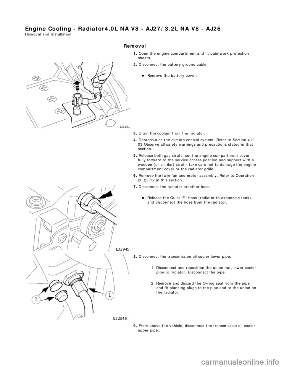
7. D
isconnect the radiator breather hose.
пЃ¬R
elease the Quick-Fit hose (radiator to expansion tank)
and disconnect the hose from the radiator.
8. Di
sconnect the transmission oil cooler lower pipe.
1. Disconnect and reposition the union nut, lower cooler pipe to radiator. Di sconnect the pipe.
2. Remove and discard the O- ring seal from the pipe
and fit blanking plugs to the pipe and to the union on
the radiator.
9. From above the vehicle, disconne ct the transmission oil cooler
upper pipe.
Page 977 of 2490
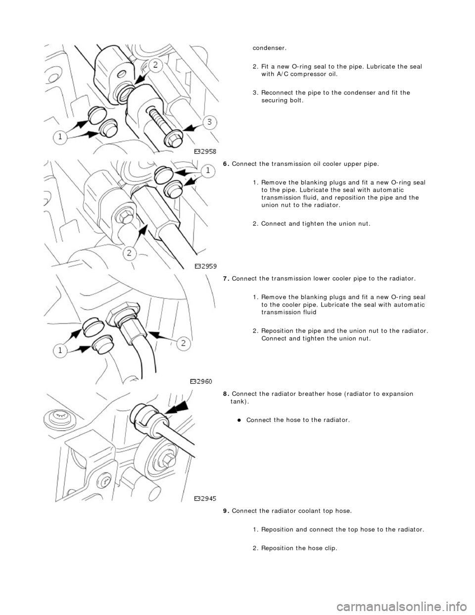
conde
nser.
2. Fit a new O-ring seal to the pipe. Lubricate the seal with A/C compressor oil.
3. Reconnect the pipe to the condenser and fit the securing bolt.
6. Conne
ct the transmission
oil cooler upper pipe.
1. Remove the blanking plugs and fit a new O-ring seal to the pipe. Lubricate the seal with automatic
transmission fluid, and re position the pipe and the
union nut to the radiator.
2. Connect and tighten the union nut.
7. Conne
ct the transmission lower cooler pipe to the radiator.
1. Remove the blanking plugs and fit a new O-ring seal to the cooler pipe. Lubricate the seal with automatic
transmission fluid
2. Reposition the pipe and th e union nut to the radiator.
Connect and tighten the union nut.
8. Connect
the radiator breather
hose (radiator to expansion
tank).
пЃ¬Conne
ct the hose to the radiator.
9. Connect the radiator coolant top hose.
1. Reposition and connect the top hose to the radiator.
2. Reposition the hose clip.
Page 978 of 2490
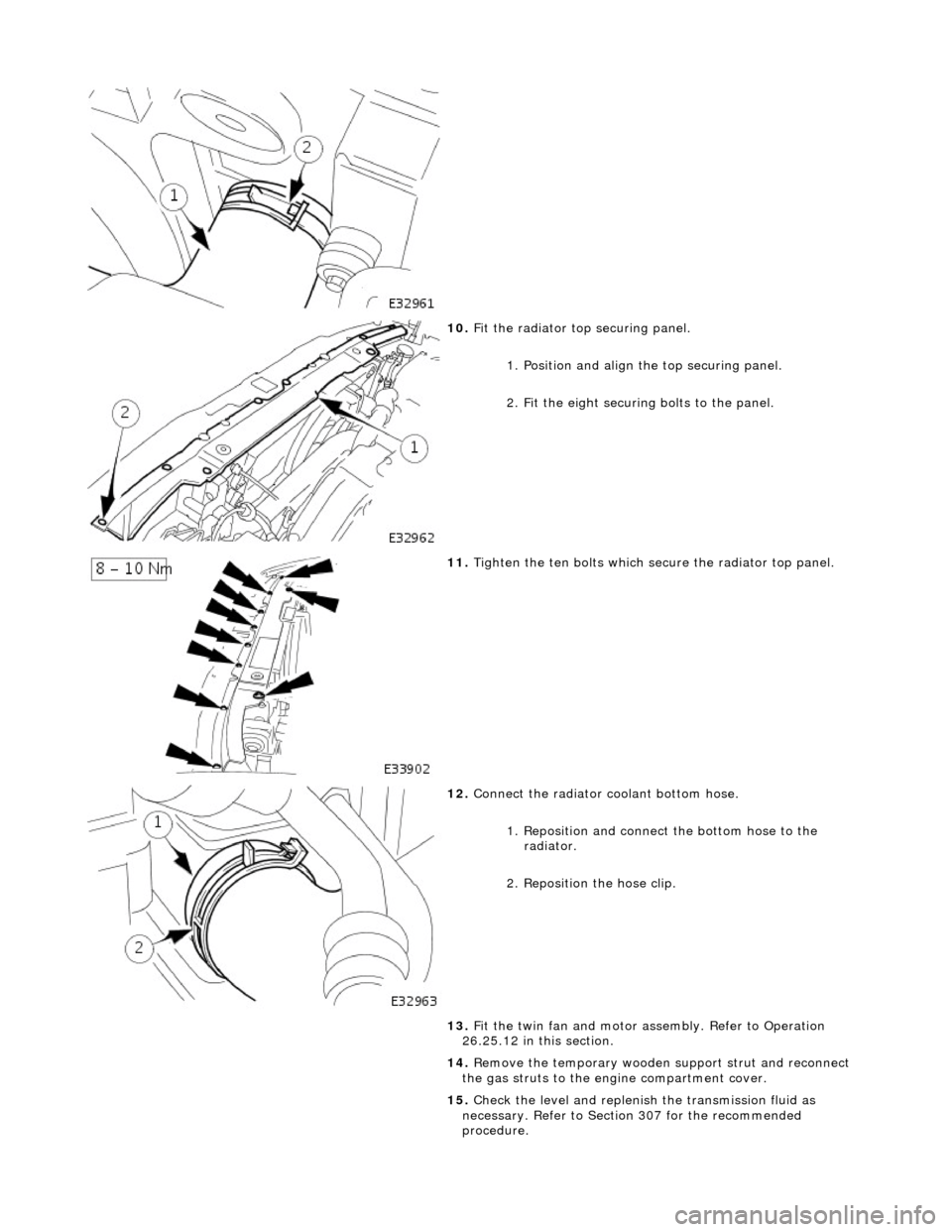
10. F
it the radiator top securing panel.
1. Position and align th e top securing panel.
2. Fit the eight securing bolts to the panel.
11. Tigh
ten the ten bolts which secu
re the radiator top panel.
12. Connect
the radiator coolant bottom hose.
1. Reposition and connect the bottom hose to the radiator.
2. Reposition the hose clip.
13. Fit the twin fan and motor assembly. Refer to Operation
26.25.12 in this section.
14. Remove the temporary wooden support strut and reconnect
the gas struts to the engine compartment cover.
15. Check the level and replenish the transmission fluid as
necessary. Refer to Section 307 for the recommended
procedure.
Page 980 of 2490
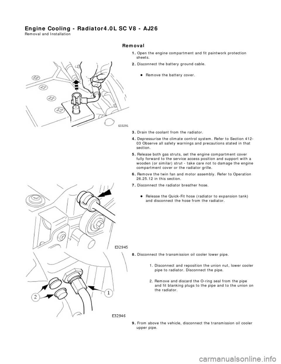
Engine Cooling - Radiator4.0L SC V8 - AJ26
Remo
val and Installation
Remov
a
l
1.
Op
en the engine compartment and fit paintwork protection
sheets.
2. Disc
onnect the batt
ery ground cable.
пЃ¬Re
move the battery cover.
3. Drain the coolant from the radiator.
4. Depressurise the climate control system. Refer to Section 412-
03 Observe all safety warnings and precautions stated in that
section.
5. Release both gas struts, set the engine compartment cover
fully forward to the service acce ss position and support with a
wooden (or similar) strut - take care not to damage the engine
compartment cover or the radiator grille.
6. Remove the twin fan and motor assembly. Refer to Operation
26.25.12 in this section.
7. Di
sconnect the radiator breather hose.
пЃ¬R
e
lease the Quick-Fit hose (radiator to expansion tank)
and disconnect the hose from the radiator.
8. Disc
onnect the transmission oil cooler lower pipe.
1. Disconnect and reposition the union nut, lower cooler pipe to radiator. Di sconnect the pipe.
2. Remove and discard the O- ring seal from the pipe
and fit blanking plugs to the pipe and to the union on
the radiator.
9. From above the vehicle, disconne ct the transmission oil cooler
upper pipe.
Page 984 of 2490

conden
ser.
2. Fit a new O-ring seal to the pipe. Lubricate the seal with A/C compressor oil.
3. Reconnect the pipe to the condenser and fit the securing bolt.
6. Conne ct
the transmission
oil cooler upper pipe.
1. Remove the blanking plugs and fit a new O-ring seal to the pipe. Lubricate the seal with automatic
transmission fluid, and re position the pipe and the
union nut to the radiator.
2. Connect and tighten the union nut.
7. Conne ct
the transmission lower cooler pipe to the radiator.
1. Remove the blanking plugs and fit a new O-ring seal to the cooler pipe. Lubricate the seal with automatic
transmission fluid
2. Reposition the pipe and th e union nut to the radiator.
Connect and tighten the union nut.
8. Connect the radiator br
eather
hose (radiator to expansion
tank).
пЃ¬Conne ct
the hose to the radiator.
9. Connect the radiator coolant top hose.
1. Reposition and connect the top hose to the radiator.
2. Reposition the hose clip.
Page 985 of 2490
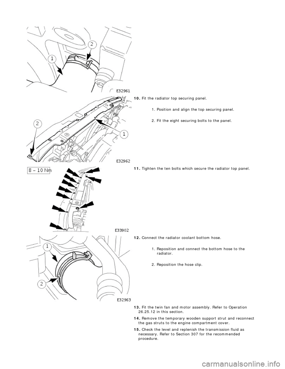
10
.
Fit the radiator top securing panel.
1. Position and align th e top securing panel.
2. Fit the eight securing bolts to the panel.
11
.
Tighten the ten bolts which secu re the radiator top panel.
12
.
Connect the radiator coolant bottom hose.
1. Reposition and connect the bottom hose to the radiator.
2. Reposition the hose clip.
13. Fit the twin fan and motor assembly. Refer to Operation
26.25.12 in this section.
14. Remove the temporary wooden support strut and reconnect
the gas struts to the engine compartment cover.
15. Check the level and replenish the transmission fluid as
necessary. Refer to Section 307 for the recommended
procedure.
Page 1064 of 2490
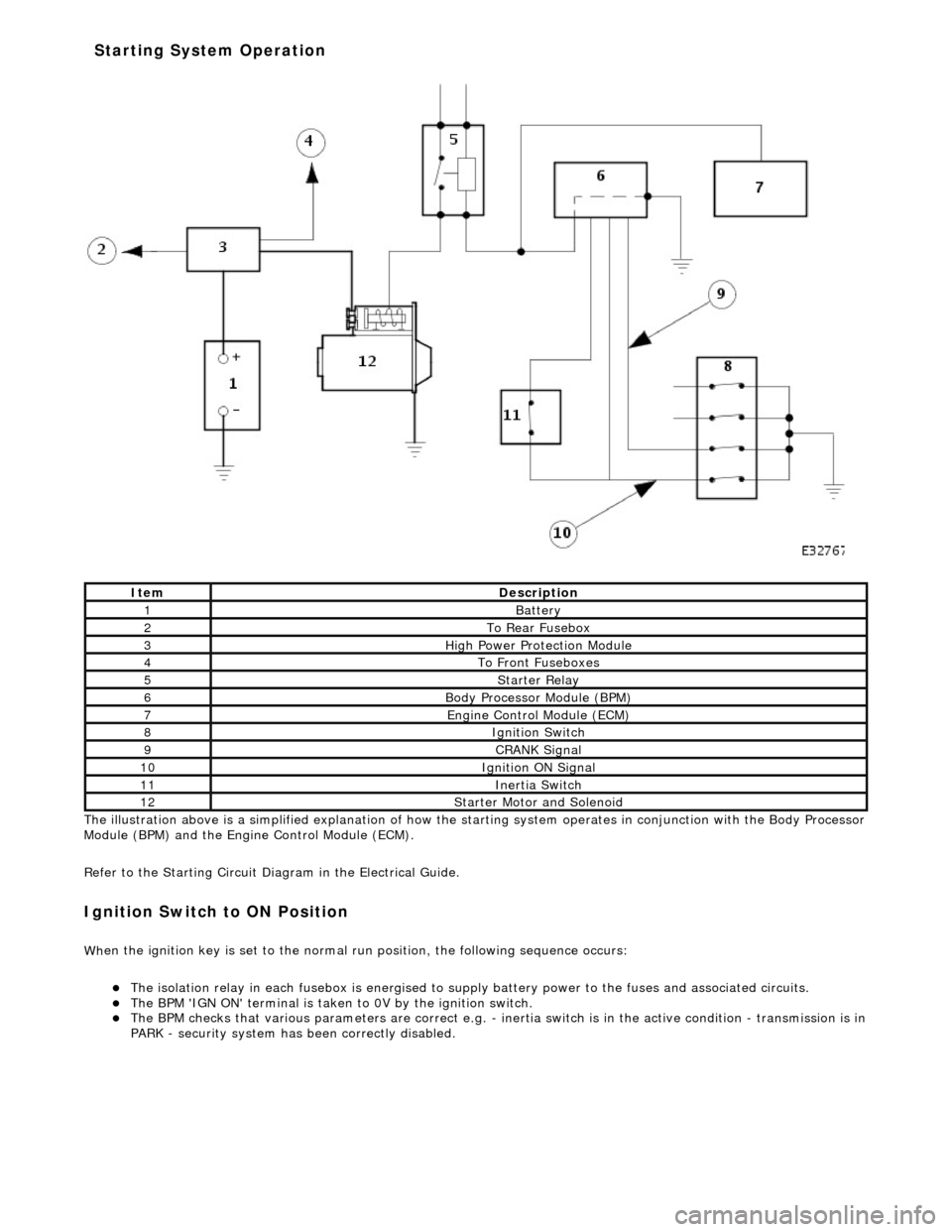
The il
lustration above is a simplified expl
anation of how the starting system operates in conjunction with the Body Processor
Module (BPM) and the Engine Control Module (ECM).
Refer to the Starting Circuit Diagram in the Electrical Guide.
I g
nition Switch to ON Position
W
h
en the ignition key is set to the normal run position, the following sequence occurs:
пЃ¬The
is
olation relay in each fusebox is
energised to supply battery power to the fuses and associated circuits.
пЃ¬The BPM 'IGN
ON' terminal
is taken to 0V by the ignition switch.
пЃ¬The BPM
checks that various parameters are correct e.g. -
inertia switch is in the active condition - transmission is in
PARK - security system has been correctly disabled.
It e
m
De
scr
iption
1Batt
ery
2To Re ar
Fusebox
3Hi
gh Power Pr
otection Module
4To Front
Fu
seboxes
5Starter Re
lay
6Body Processor M
odule (BPM)
7Engine
C
ontrol Module (ECM)
8Ignition Switch
9CRANK Signal
10Ignition ON Signal
11Inertia Switch
12St
arte
r Motor and Solenoid
Starting System Operation