JAGUAR X308 1998 2.G Repair Manual
X308 1998 2.G
JAGUAR
JAGUAR
https://www.carmanualsonline.info/img/21/7640/w960_7640-0.png
JAGUAR X308 1998 2.G Repair Manual
Page 1485 of 2490
3. Connect the battery and fit the battery cover.
Reset the radio and the clock.
Page 1486 of 2490
Automatic Transmission/Transaxle External Controls - 4.0L NA V8 -
AJ27/3.2L NA V8 - AJ26 - Kickdown Switch
Removal and Installation
Removal
Installation
1. Disconnect the kickdown switch multiplug.
Move the carpet for access.
2. Remove the kickdown switch.
Rotate counter-clockwise.
1. Installation is th e reverse of the re moval procedure.
2. The kickdown switch MUST be adjusted in accordance with
(44.15.38).
Page 1491 of 2490
Automatic Transmission/Transaxle External Controls - 4.0L NA V8 -
AJ27/3.2L NA V8 - AJ 26 - Selector Lever Indicator Assembly
Removal and Installation
Removal
Installation
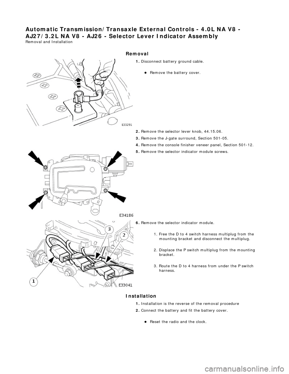
1. Disconnect battery ground cable.
Remove the battery cover.
2. Remove the selector lever knob, 44.15.06.
3. Remove the J-gate surround, Section 501-05.
4. Remove the console finisher ve neer panel, Section 501-12.
5. Remove the selector indicator module screws.
6. Remove the selector indicator module.
1. Free the D to 4 switch harness multiplug from the mounting bracket and disc onnect the multiplug.
2. Displace the P switch multiplug from the mounting bracket.
3. Route the D to 4 harnes s from under the P switch
harness.
1. Installation is the revers e of the removal procedure
2. Connect the battery and fit the battery cover.
Reset the radio and the clock.
Page 1492 of 2490
Automatic Transmission/Transaxle External Controls - 4.0L NA V8 -
AJ27/3.2L NA V8 - AJ26 - Se lector Lever Indicator Disc
Removal and Installation
Removal
Installation
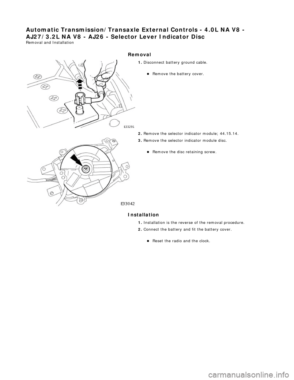
1. Disconnect battery ground cable.
Remove the battery cover.
2. Remove the selector indicator module; 44.15.14.
3. Remove the selector indicator module disc.
Remove the disc retaining screw.
1. Installation is th e reverse of the re moval procedure.
2. Connect the battery and fit the battery cover.
Reset the radio and the clock.
Page 1493 of 2490
Automatic Transmission/Transaxle External Controls - 4.0L NA V8 -
AJ27/3.2L NA V8 - AJ26 - Selector Lever Switch
Removal and Installation
Removal
Installation
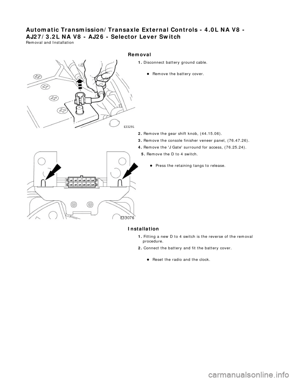
1. Disconnect battery ground cable.
Remove the battery cover.
2. Remove the gear shift knob, (44.15.06).
3. Remove the console finisher veneer panel, (76.47.26).
4. Remove the 'J Gate' surroun d for access, (76.25.24).
5. Remove the D to 4 switch.
Press the retaining tangs to release.
1. Fitting a new D to 4 switch is the reverse of the removal
procedure.
2. Connect the battery and fit the battery cover.
Reset the radio and the clock.
Page 1494 of 2490
Automatic Transmission/Transaxle External Controls - 4.0L NA V8 -
AJ27/3.2L NA V8 - AJ26 - Selector Lever Knob
Removal and Installation
Removal
Installation
1. Remove the select or lever knob.
1. Slacken the ferrule, rotate clock-wise.
2. Rotate the knob coun ter-clockwise to remove.
1. Refer to the illustration
1. Fit the knob.
2. Tighten the ferru le to the specified torque figure.
Page 1498 of 2490
19. Inst
all the slide plate.
Install
the four sl
ide plate screws.
20 . Fi
t the gear shift assembly.
Inst
all th
e four nuts.
21 . Asse
mble the cable to the gear shift assembly.
1. Locate the outer cable.
2. Fit and tighten the cable securing nut to the specified torque figure.
22. Adjust, or verify, the cable in accordance with 44.15.07.
23. Further installation is the reve rse of the removal procedure.
24. Connect the battery and fit the battery cover.
Reset the radio an
d the clock.
Page 1512 of 2490
Automatic Transmission/Transaxle External Contro ls - 4.0L SC V8 - AJ26 -
Kickdown Switch
Removal and Installation
Removal
Installation
1. Disconnect the kickdown switch multiplug.
Move the carpet for access.
2. Remove the kickdown switch.
Rotate counter-clockwise.
1. Installation is th e reverse of the re moval procedure.
2. The kickdown switch MUST be adjusted in accordance with
(44.15.38).
Page 1521 of 2490
Automatic Transmission/Transaxle External Contro ls - 4.0L SC V8 - AJ26 -
Selector Lever Knob
Removal and Installation
Removal
Installation
1.
Disconnect the vehicle battery ground lead.
2. Remove the select or lever knob.
1. Slacken the ferrule, rotate clockwise.
2. Rotate the knob coun ter-clockwise to remove.
1. Refer to the illustration.
1. Fit the knob.
2. Refer to the illustration.
Page 1738 of 2490

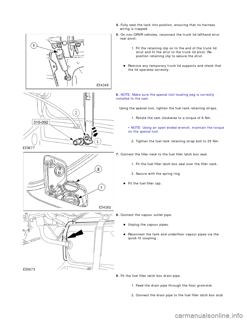
4. Full
y seat the tank into positi
on, ensuring that no harness
wiring is trapped.
5. On non-
ORVR vehicles, reconnec
t the trunk lid lefthand strut
rear pivot.
1. Fit the retaining clip on to the end of the trunk lid strut and fit the strut to the trunk lid pivot. Re-
position retaining clip to secure the strut.
Re
move any temporary trunk lid supports and check that
the lid operates correctly.
6. NOTE
: Make sure the special tool locating peg is correctly
installed to the cam.
Using the special tool, tighten the fuel tank retaining straps.
1. Rotate the cam clockwise to a torque of 6 Nm.
• NOTE: Using an open ended wrench, maintain the torque
on the special tool.
2. Tighten the fuel tank reta ining strap bolt to 25 Nm.
7. Connect the fi
ller neck to the fuel filler latch box seal.
1. Fit the fuel filler latch box seal over the filler neck.
2. Secure with the spring ring
F i
t the fuel filler cap.
8. Connect the vapour outlet pip
e.
Unplug the v
a
pour pipes.
Reconn
ect th
e tank and underfloor vapour pipes via the
quick-fit coupling .
9. Fit the fuel filler latch box drain pipe.
1. Feed the drain pipe th rough the floor grommet.
2. Connect the drain pipe to the fuel filler latch box stub


