clock JAGUAR X308 1998 2.G Owner's Guide
[x] Cancel search | Manufacturer: JAGUAR, Model Year: 1998, Model line: X308, Model: JAGUAR X308 1998 2.GPages: 2490, PDF Size: 69.81 MB
Page 883 of 2490
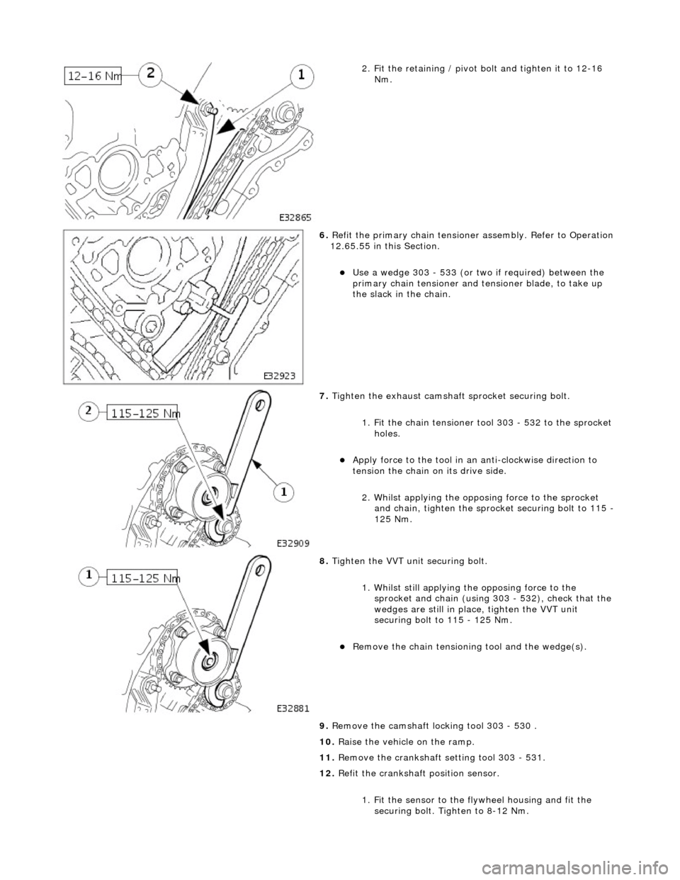
2. Fit the retaining / pivot bolt and tighten it to 12-16 Nm.
6. Refit the primary chain tensione r assembly. Refer to Operation
12.65.55 in this Section.
Use a wedge 303 - 533 (or two if required) between the
primary chain tensioner and te nsioner blade, to take up
the slack in the chain.
7. Tighten the exhaust camshaft sprocket securing bolt.
1. Fit the chain tensioner tool 303 - 532 to the sprocket holes.
Apply force to the tool in an anti-clockwise direction to
tension the chain on its drive side.
2. Whilst applying the opposing force to the sprocket and chain, tighten the sprock et securing bolt to 115 -
125 Nm.
8. Tighten the VVT unit securing bolt.
1. Whilst still applying the opposing force to the
sprocket and chain (using 303 - 532), check that the
wedges are still in place, tighten the VVT unit
securing bolt to 115 - 125 Nm.
Remove the chain tensioning tool and the wedge(s).
9. Remove the camshaft locking tool 303 - 530 .
10. Raise the vehicle on the ramp.
11. Remove the crankshaft setting tool 303 - 531.
12. Refit the crankshaft position sensor.
1. Fit the sensor to the fl ywheel housing and fit the
securing bolt. Tighten to 8-12 Nm.
Page 889 of 2490
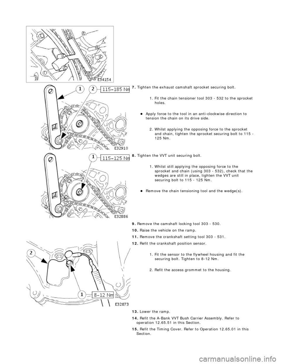
7. Tighten the exhaust camshaft sprocket securing bolt.
1. Fit the chain tensioner tool 303 - 532 to the sprocket holes.
Apply force to the tool in an anti-clockwise direction to
tension the chain on its drive side.
2. Whilst applying the opposing force to the sprocket and chain, tighten the sprock et securing bolt to 115 -
125 Nm.
8. Tighten the VVT unit securing bolt.
1. Whilst still applying the opposing force to the
sprocket and chain (using 303 - 532), check that the
wedges are still in place, tighten the VVT unit
securing bolt to 115 - 125 Nm.
Remove the chain tensioning tool and the wedge(s).
9. Remove the camshaft locking tool 303 - 530.
10. Raise the vehicle on the ramp.
11. Remove the crankshaft setting tool 303 - 531.
12. Refit the crankshaft position sensor.
1. Fit the sensor to the fl ywheel housing and fit the
securing bolt. Tighten to 8-12 Nm.
2. Refit the access grommet to the housing.
13. Lower the ramp.
14. Refit the A-Bank VVT Bush Carrier Assembly. Refer to
operation 12.65.51 in this Section.
15. Refit the Timing Cover. Refer to Operation 12.65.01 in this
Section.
Page 923 of 2490
be 'hun
g up' within the engine because it is not up to operating
temperature.
Should the oil level subsequently be topped-up, the level could
become too high, causing oil burning.
Typically, 0.875L is hung up.
Refill the engine with the correct specification engine oil.
58. Refill the automatic transmission. Refer to Section 307-01A,
Operation 44.24. 02.
59. Refill and bleed the power stee ring system. Refer to Section
211-02 General Procedures.
60. Repressurise the air conditioni ng system. Refer to Operation
82.30.30 and note all Wa rnings and Cautions.
61
.
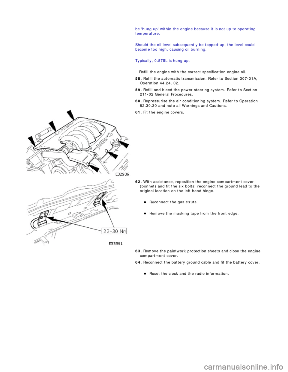
Fit the engine covers.
62
.
With assistance, reposition the engine compartment cover
(bonnet) and fit the si x bolts; reconnect the ground lead to the
original location on the left hand hinge.
Re
connect the gas struts.
R
emove the masking tape from the front edge.
63. Remove the paintwork protection sheets and close the engine
compartment cover.
64. Reconnect the battery ground cable and fit the battery cover.
Re
set the clock and the radio information.
Page 969 of 2490
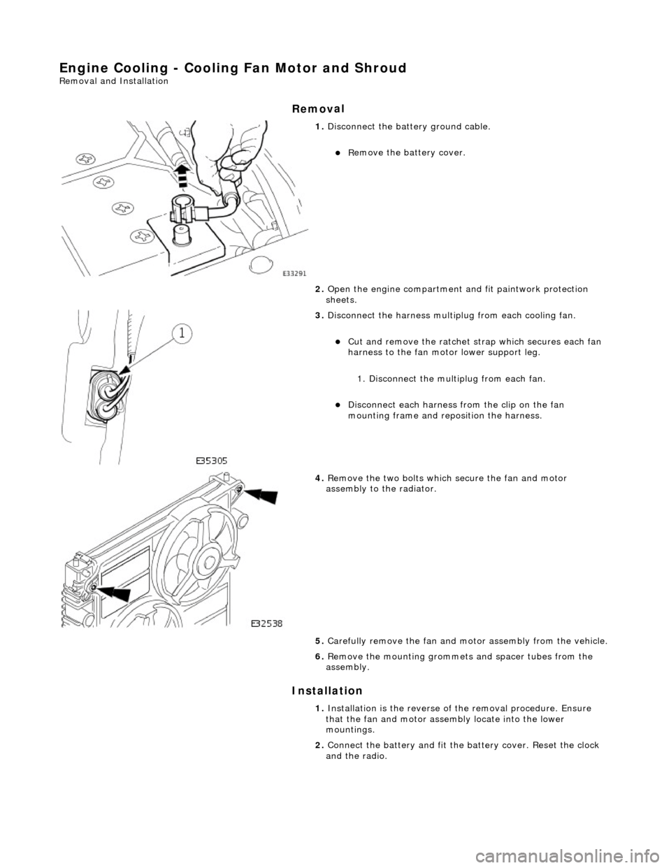
Engine Cooling - Cooling Fan Motor and Shroud
Re
moval and Installation
Remov
al
Installation
1.
Di
sconnect the batt
ery ground cable.
R
emove the battery cover.
2. Open the engine compartment and fit paintwork protection
sheets.
3. Disc
onnect the harness multip
lug from each cooling fan.
Cut an
d remove the ratchet st
rap which secures each fan
harness to the fan moto r lower support leg.
1. Disconnect the mult iplug from each fan.
Di
sconnect each harness
from the clip on the fan
mounting frame and repo sition the harness.
4. R
emove the two bolts which
secure the fan and motor
assembly to the radiator.
5. Carefully remove the fan and mo tor assembly from the vehicle.
6. Re
move the mounting grommets
and spacer tubes from the
assembly.
1. Installation is the reverse of the remova l procedure. Ensure
that the fan and motor assembly locate into the lower
mountings.
2. Connect the battery and fit the battery cover. Reset the clock
and the radio.
Page 979 of 2490
16
.
Refill the cooling system. Refer to the Refill procedure in
General Procedures.
17. Repressurise the climate cont rol system. Refer to Section
412-03 Observe all safety warnin gs and precautions stated in
that section.
18. Close the engine compartment cover.
19. Connect the battery and fit the battery cover. Reset the clock
and the radio.
Page 986 of 2490
16
. Re
fill the cooling system. Refer to the Refill procedure in
General Procedures.
17. Repressurise the climate cont rol system. Refer to Section
412-03 Observe all safety warnin gs and precautions stated in
that section.
18. Close the engine compartment cover.
19. Connect the battery and fit the battery cover. Reset the clock
and the radio.
Page 1001 of 2490
Engine Cooling - Water Pump4.0L NA V8 - AJ27/ 3.2L NA V8 - AJ26
Re
moval and Installation
Remov
al
1.
O
pen the engine compartment and fit paintwork protection
sheets.
2. Drain the cooling system.
For additional information, refer to Cooling System Draining,
Fillin
g and Bleeding
- Vehicles W
ithout: Supercharger
in
this
section.
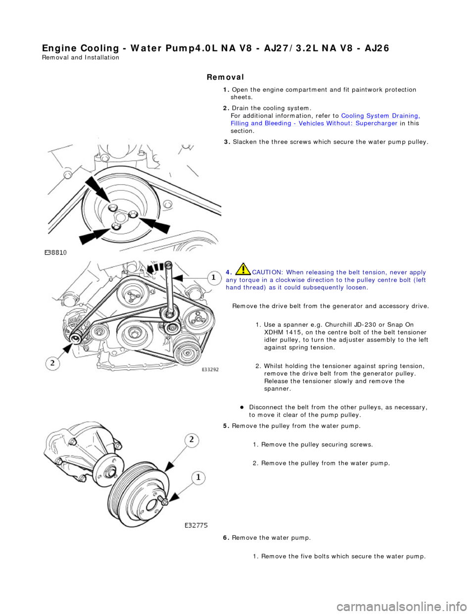
3. Sl
acken the three screws which
secure the water pump pulley.
4. CAUTI
ON: When releasing the
belt tension, never apply
any torque in a clockwise direction to the pulley ce ntre bolt (left
hand thread) as it could subsequently loosen.
Remove the drive belt from the generator and accessory drive.
1. Use a spanner e.g. Churchill JD-230 or Snap On XDHM 1415, on the centre bo lt of the belt tensioner
idler pulley, to turn the adju ster assembly to the left
against spring tension.
2. Whilst holding the tensioner against spring tension, remove the drive belt from the generator pulley.
Release the tensioner sl owly and remove the
spanner.
D
isconnect the belt from the ot
her pulleys, as necessary,
to move it clear of the pump pulley.
5. Re
move the pulley from the water pump.
1. Remove the pulley securing screws.
2. Remove the pulley from the water pump.
6. Remove the water pump.
1. Remove the five bolts wh ich secure the water pump.
Page 1004 of 2490

Engine Cooling - Water Pump4.0L SC V8 - AJ26
Remo
val and Installation
Remov
a
l
1.
Op
en the engine compartment and fit paintwork protection
sheets.
2. Drain the cooling system.
For additional information, refer to Cooling System Draining,
Filling and Bleedin
g
- Vehicles With
: Supercharger in this
section.
3. Remove the supercharger driv e belt. Refer to Operation
18.50.08.
4. Slacken the three screws whi
ch
secure the water pump pulley.
5. CAUTIO
N: When releasing the
belt tension, never apply
any torque in a clockwise direction to the pulley ce ntre bolt (left
hand thread) as it could subsequently loosen.
Remove the drive belt from the generator and accessory drive.
1. Use a spanner e.g. Churchill JD-230 or Snap On XDHM 1415, on the centre bo lt of the belt tensioner
idler pulley, to turn the adju ster assembly to the left
against spring tension.
2. Whilst holding the tensioner against spring tension, remove the drive belt from the generator pulley.
Release the tensioner sl owly and remove the
spanner.
Di
sconnect the belt from the ot
her pulleys, as necessary,
to move it clear of the pump pulley.
6. Remove t
he pulley from the water pump.
1. Remove the pulley securing screws.
2. Remove the pulley from the water pump.
7. Remove the water pump.
Page 1007 of 2490

W
ater Pump Pulley Vehicles Without: Supercharger
26.50.05
Removal
1. Open the engine compartment and fit paintwork protection sheets.
2
. Slacken the three screws which secure the water pump pulley.
3
.
C
AUTION:
When releasing the belt tension, never apply any torque in a clockwise direction to the pulley
centre bolt (left hand thread) as it could subsequently loosen.
Remove the drive belt from the generator and accessory drive. 1. Use a spanner e.g. Churchill JD-230 or Snap On XDHM 1415, on the centre bolt of the belt tensioner idler pulley, to turn the adjuster assembly to the left against spring tension.
Page 1009 of 2490

W
ater Pump Pulley Vehicles With: Supercharger
26.50.05
Removal
1. Open the engine compartment and fit paintwork protection sheets.
2. Remove the supercharger drive belt. Refer to Operation <<18.50.08>>.
3
. Slacken the three screws which secure the water pump pulley.
4
.
C
AUTION:
When releasing the belt tension, never apply any torque in a clockwise direction to the pulley
centre bolt (left hand thread) as it could subsequently loosen.