ECU JAGUAR X308 1998 2.G Workshop Manual
[x] Cancel search | Manufacturer: JAGUAR, Model Year: 1998, Model line: X308, Model: JAGUAR X308 1998 2.GPages: 2490, PDF Size: 69.81 MB
Page 2146 of 2490

tighten securing bolts.
2.
Position potentiometer on gearbox.
3. Engage drive shaft in po tentiometer and gearbox.
4. Install potentiometer retaining plate.
5. Rotate potentiometer to en gage retaining plate tang.
6. Fit and tighten retaining plate/gearbox securing bolts.
7. Fit and fully seat new gearbo x drive shaft securing clip
8. Fit seat cover RH side to seat frame and fully seat securing
clips.
9. Fit seat cover LH side to seat frame and fully seat securing
clips.
10. Fit seat cover to lower frame retaining strip.
11. Position seat for acces and fit seat back finisher. Refer to
76.70.09.
12. Install seat in vehicle. Refer to 76.70.01.
13. Connect ground cable to batt ery terminal and fit battery
cover. Refer to 86.15.15.
14. Motor seat fully forward and fully rearward, checking for
satisfactory operation.
15. Return seat to original position.
Page 2147 of 2490
Seating - Front Seat Track
Removal and Installation
Removal
1. WARNING: FOLLOWING DISCONNECTION OF THE
BATTERY A PERIOD OF AT LEAST ONE MINUTE MUST BE
ALLOWED TO ELAPSE BEFORE WORKING ON A FRONT SEAT WITH
A SIDE AIRBAG FITTED.
Remove battery cover and disc onnect ground cable from
battery terminal. Refer to 86,.15.19.
2. Remove front seat from vehicle. Refer to 76.70.01.
3. Invert seat for access.
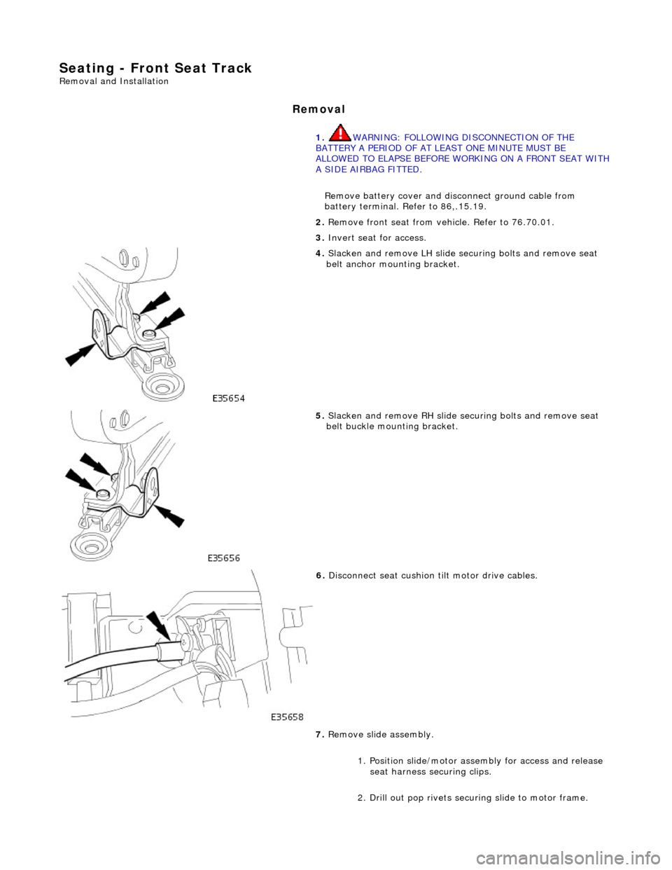
4. Slacken and remove LH slide se curing bolts and remove seat
belt anchor mounting bracket.
5. Slacken and remove RH slide se curing bolts and remove seat
belt buckle moun ting bracket.
6. Disconnect seat cushion tilt motor drive cables.
7. Remove slide assembly.
1. Position slide/motor assembly for access and release seat harness securing clips.
2. Drill out pop rivets securing slide to motor frame.
Page 2148 of 2490

Installation
8. Withdraw LH slide from seat motor potentiometer/gearbox
assembly.
1. Fit and fully seat slide to po tentiometer/gearbox assembly.
2. Position motor frame on slide assembly and secure with new
pop rivets.
3. Connect seat cushion tilt motor drive cables.
4. Secure seat harness in clips.
5. Position slide assembly on seat.
6. Fit and align RH seat belt bu ckle mounting bracket between
slide and seat pivot bracket and fit but do not tighten securing
bolts.
7. Fit and align LH seat belt an chor bracket between slide and
seat pivot bracket an d fit but do not tighten securing bolts.
8. Fit but do not tighten RH and LH slide front securing bolts.
9. Finally tighten slide front and rear securing bolts.
10. Fit front seat to vehi cle. Refer to 76.70.01.
Page 2150 of 2490
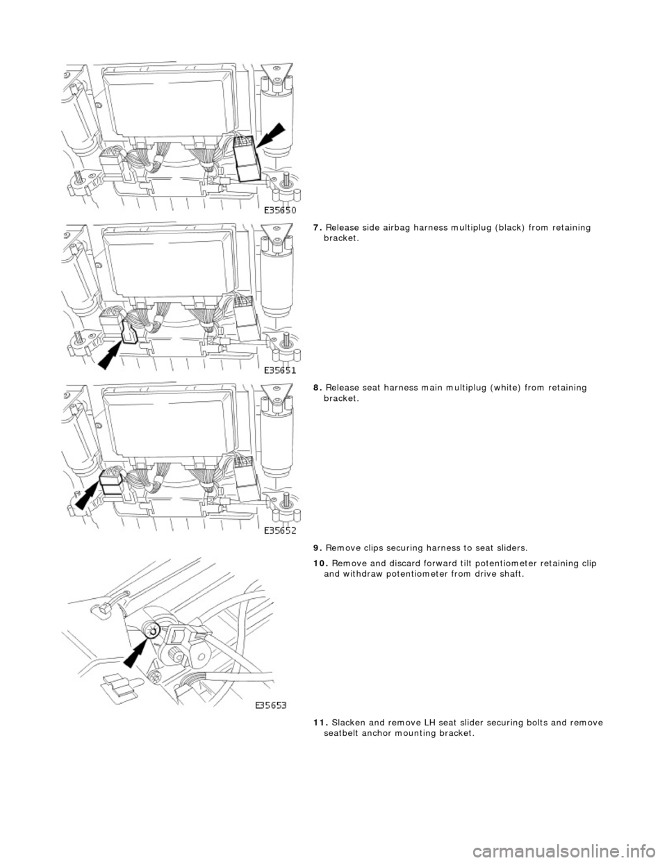
7. Release side airbag harness multiplug (black) from retaining
bracket.
8. Release seat harness main mu ltiplug (white) from retaining
bracket.
9. Remove clips securing harness to seat sliders.
10. Remove and discard forward tilt potentiometer retaining clip
and withdraw potentiometer from drive shaft.
11. Slacken and remove LH seat slid er securing bolts and remove
seatbelt anchor mounting bracket.
Page 2151 of 2490
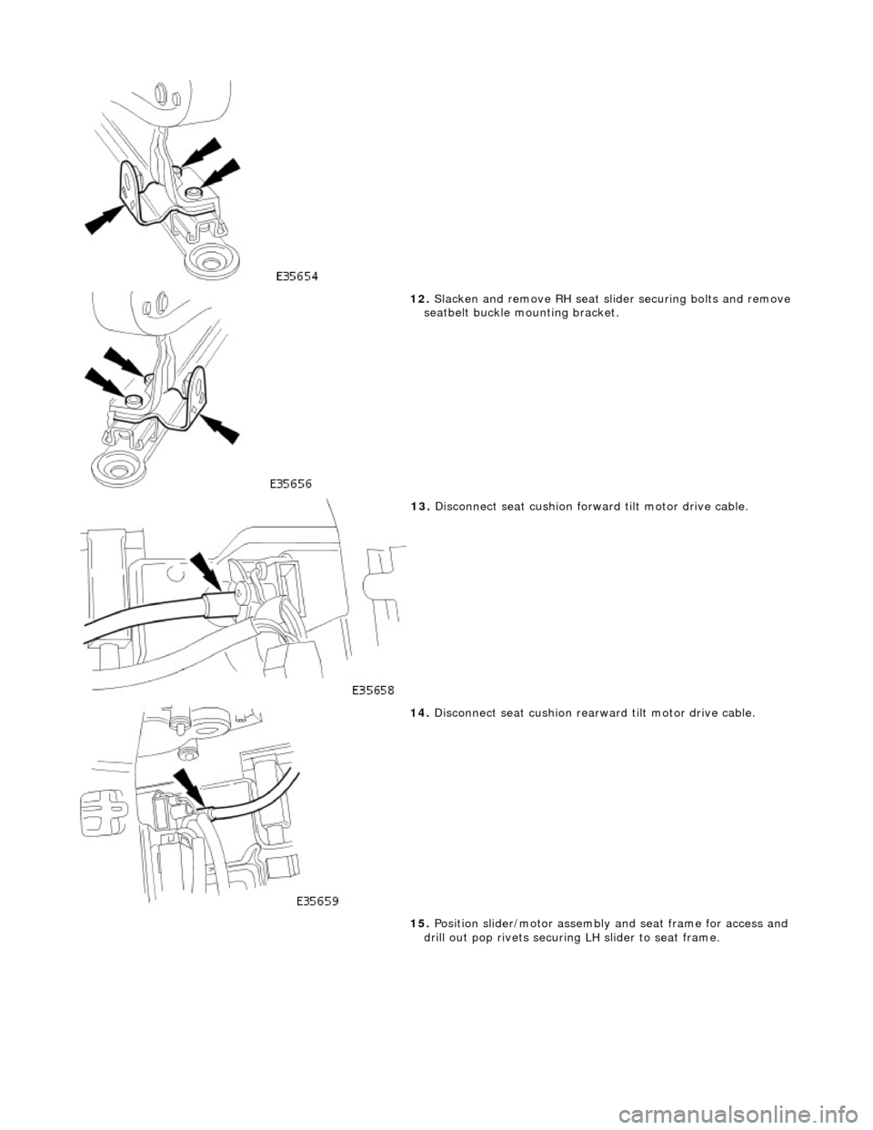
12. Slacken and remove RH seat slider securing bolts and remove seatbelt buckle mo unting bracket.
13. Disconnect seat cushion forward tilt motor drive cable.
14. Disconnect seat cushion rearward tilt motor drive cable.
15. Position slider/motor assembly and seat frame for access and
drill out pop rivets securing LH slider to seat frame.
Page 2152 of 2490

16. Slacken and remove bolt securi ng motor/ potentiometer and
gearbox to LH slider and re move LH slider assembly.
17. Release motor/potentiometer an d gearbox harness multiplug
from mounting bracket an d disconnect multiplug.
18. Slacken and remove motor/pote ntiometer to frame securing
bolts.
19. Disconnect RH seat slider gearbox drive cable from
motor/potentiometer.
Page 2153 of 2490
I
nstallation
20
.
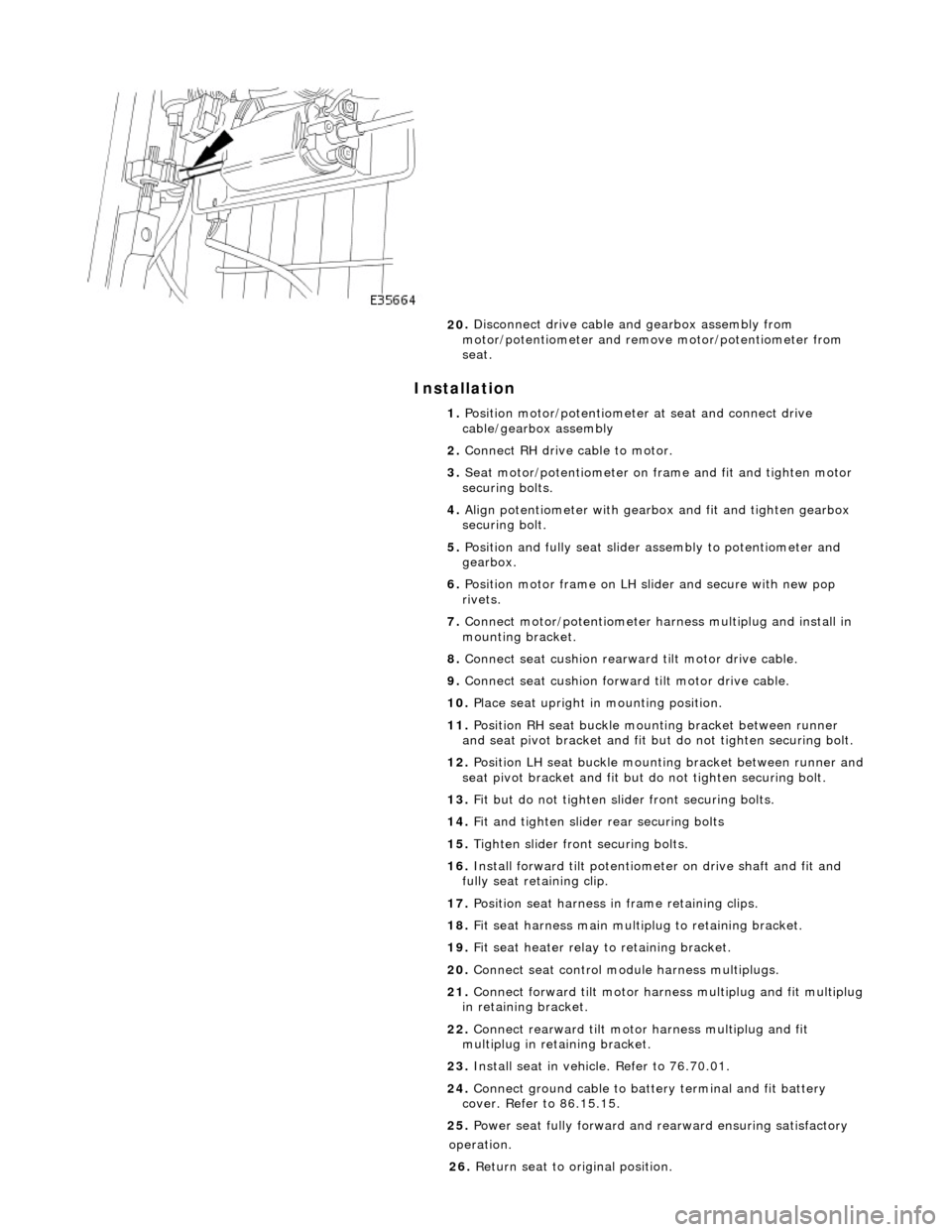
Disconnect drive cable and gearbox assembly from
motor/potentiometer and remo ve motor/potentiometer from
seat.
1. Position motor/potentiometer at seat and connect drive
cable/gearbox assembly
2. Connect RH drive cable to motor.
3. Seat motor/potentiometer on fra me and fit and tighten motor
securing bolts.
4. Align potentiometer with gearbo x and fit and tighten gearbox
securing bolt.
5. Position and fully seat slider assembly to potentiometer and
gearbox.
6. Position motor frame on LH sl ider and secure with new pop
rivets.
7. Connect motor/potentiometer harness multiplug and install in
mounting bracket.
8. Connect seat cushion rearward tilt motor drive cable.
9. Connect seat cushion forwar d tilt motor drive cable.
10. Place seat upright in mounting position.
11. Position RH seat buckle mounting bracket between runner
and seat pivot bracket and fit but do not tighten securing bolt.
12. Position LH seat buckle mounting bracket between runner and
seat pivot bracket an d fit but do not tighten securing bolt.
13. Fit but do not tighten slider front securing bolts.
14. Fit and tighten slider rear securing bolts
15. Tighten slider front securing bolts.
16. Install forward tilt potentiome ter on drive shaft and fit and
fully seat retaining clip.
17. Position seat harness in frame retaining clips.
18. Fit seat harness main multiplug to retaining bracket.
19. Fit seat heater relay to retaining bracket.
20. Connect seat control module harness multiplugs.
21. Connect forward tilt motor harn ess multiplug and fit multiplug
in retaining bracket.
22. Connect rearward tilt motor harness multiplug and fit
multiplug in retaining bracket.
23. Install seat in vehicle. Refer to 76.70.01.
24. Connect ground cable to batt ery terminal and fit battery
cover. Refer to 86.15.15.
25. Power seat fully forward and rearward ensuring satisfactory
op
eration.
26. Return seat to original position.
Page 2154 of 2490
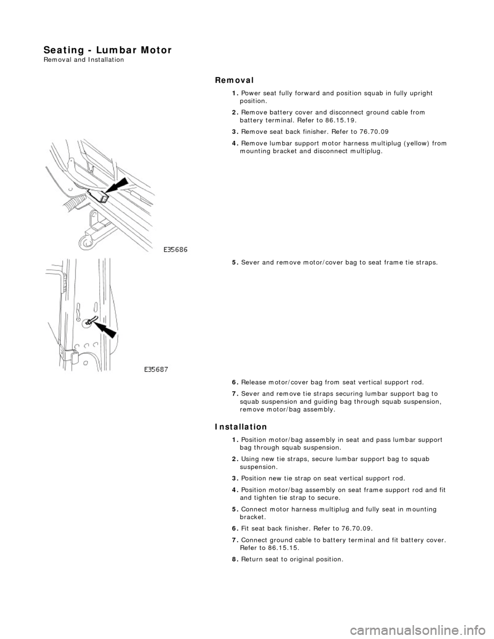
Seating - Lumbar Motor
Removal and Installation
Removal
Installation
1.
Power seat fully forward and position squab in fully upright
position.
2. Remove battery cover and disc onnect ground cable from
battery terminal. Refer to 86.15.19.
3. Remove seat back fini sher. Refer to 76.70.09
4. Remove lumbar support motor ha rness multiplug (yellow) from
mounting bracket and di sconnect multiplug.
5. Sever and remove motor/cover ba g to seat frame tie straps.
6. Release motor/cover bag from seat vertical support rod.
7. Sever and remove tie straps se curing lumbar support bag to
squab suspension and guiding bag through squab suspension,
remove motor/bag assembly.
1. Position motor/bag assembly in seat and pass lumbar support
bag through squab suspension.
2. Using new tie straps , secure lumbar support bag to squab
suspension.
3. Position new tie strap on se at vertical support rod.
4. Position motor/bag assembly on seat frame support rod and fit
and tighten tie st rap to secure.
5. Connect motor harness multiplug and fully seat in mounting
bracket.
6. Fit seat back finisher. Refer to 76.70.09.
7. Connect ground cable to battery terminal and fit battery cover.
Refer to 86.15.15.
8. Return seat to original position.
Page 2155 of 2490
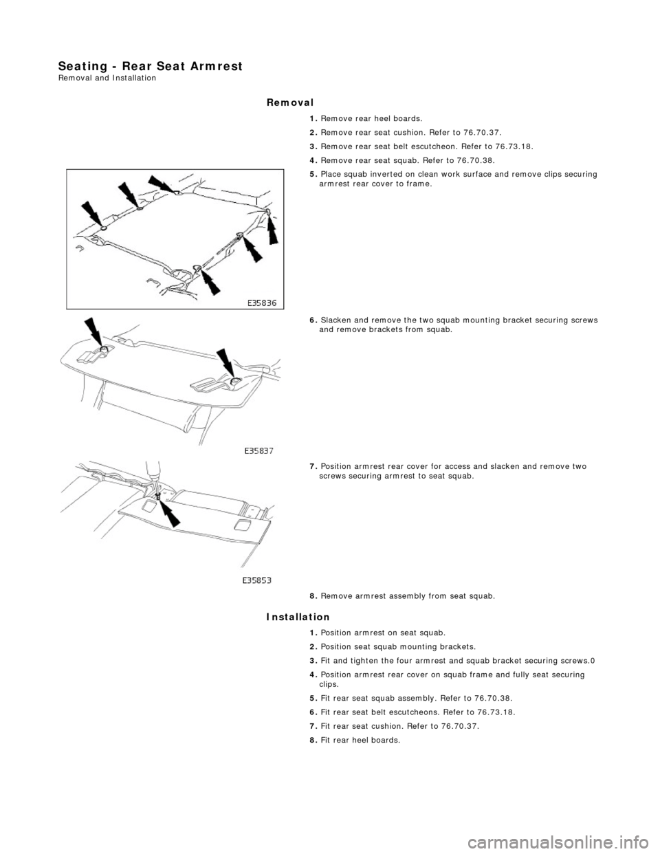
Seating - Rear Seat Armrest Removal and Installation
Removal
Installation
1.
Remove rear heel boards.
2. Remove rear seat cushion. Refer to 76.70.37.
3. Remove rear seat belt escu tcheon. Refer to 76.73.18.
4. Remove rear seat squab. Refer to 76.70.38.
5. Place squab inverted on clean work surface and remove clips securing
armrest rear cover to frame.
6. Slacken and remove the two squab mounting bracket securing screws
and remove brackets from squab.
7. Position armrest rear cover for access and slacken and remove two
screws securing armrest to seat squab.
8. Remove armrest assembly from seat squab.
1. Position armrest on seat squab.
2. Position seat squab mounting brackets.
3. Fit and tighten the four armrest and squab bracket securing screws.0
4. Position armrest rear cover on sq uab frame and fully seat securing
clips.
5. Fit rear seat squab assembly. Refer to 76.70.38.
6. Fit rear seat belt escutc heons. Refer to 76.73.18.
7. Fit rear seat cushion. Refer to 76.70.37.
8. Fit rear heel boards.
Page 2156 of 2490
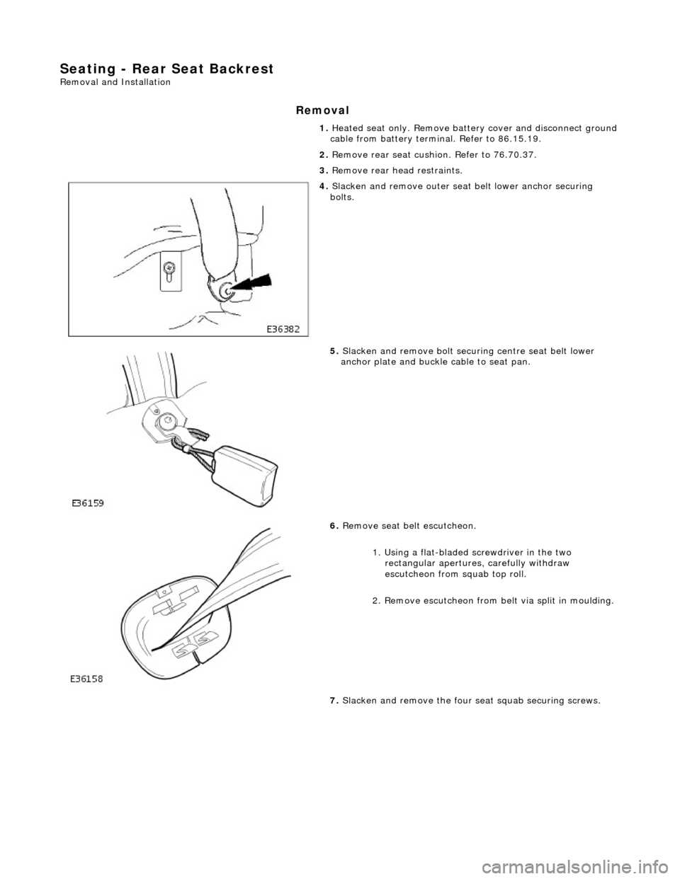
Seating - Rear Seat Backrest
Removal and Installation
Removal
1. Heated seat only. Remove batt ery cover and disconnect ground cable from battery terminal. Refer to 86.15.19.
2. Remove rear seat cushion. Refer to 76.70.37.
3. Remove rear he ad restraints.
4. Slacken and remove outer seat belt lower anchor securing
bolts.
5. Slacken and remove bolt securi ng centre seat belt lower
anchor plate and buckle cable to seat pan.
6. Remove seat be lt escutcheon.
1. Using a flat-bladed screwdriver in the two rectangular apertures, carefully withdraw
escutcheon from squab top roll.
2. Remove escutcheon from belt via split in moulding.
7. Slacken and remove the four seat squab securing screws.