transmission fluid JAGUAR X308 1998 2.G Workshop Manual
[x] Cancel search | Manufacturer: JAGUAR, Model Year: 1998, Model line: X308, Model: JAGUAR X308 1998 2.GPages: 2490, PDF Size: 69.81 MB
Page 16 of 2490

В В В В В В В В В В В В В В В В В В В В KnockВ Sensor В (KS) В RH В (18.30.93) В
В В В В В В В В В В В В В В В В В В В В
VariableВ Camshaft В Timing В (VCT) В Oil В Co ntrol
В
Solenoid В (18.30.90) В
В
В В В В В В В В
307: В Automatic В Transmission/Transaxle В
В
В В В В В В В В В В В В 307‐01A :В Automatic В Transmission/Transaxle  ‐ 3.2L В NA В V8  ‐ AJ26/4.0LВ NAВ V8  ‐ AJ27 В
В В В В В В В В В В В В В В В В Specification В
В В В В В В В В В В В В В В В В Description В and В Operation В
В В В В В В В В В В В В В В В В В В В В TransmissionВ DescriptionВ
В В В В В В В В В В В В В В В В Diagnosis В and В Testing В
В В В В В В В В В В В В В В В В В В В В DiagnosticВ Strategy В
В В В В В В В В В В В В В В В В GeneralВ Procedures В
В В В В В В В В В В В В В В В В В В В В TransmissionВ FluidВ Drain В and В Refill В (44.24.02) В
                In‐Ve
hicle В Repair В
В В В В В В В В В В В В В В В В В В В В ElectronicВ PressureВ ControlВ (EPC)В Solenoid В (44.15.51) В
В В В В В В В В В В В В В В В В В В В В ExtensionВ Housing В Seal В (44.20.18) В
В В В В В В В В В В В В В В В В В В В В ExtensionВ Housing В O ‐Ring В Seal В (44.20.19) В
В В В В В В В В В В В В В В В В В В В В MainВ ControlВ ValveВ BodyВ (44.40.01) В
В В В В В В В В В В В В В В В В В В В В OutputВ Shaft В Speed В (OSS) В Sensor В (44.15.41) В
В В В В В В В В В В В В В В В В В В В В ShiftВ Solenoids В (SS) В (44.15.50) В
В В В В В В В В В В В В В В В В В В В В TransmissionВ ControlВ Module В (TCM) В (44.15.32) В
В В В В В В В В В В В В В В В В В В В В TransmissionВ FluidВ Filter В (44.24.07) В
В В В В В В В В В В В В В В В В В В В В TransmissionВ Fl
uid В Pan В (44.24.04) В
В В В В В В В В В В В В В В В В В В В В TransmissionВ FluidВ Pan В Gasket В (44.24.05) В
В В В В В В В В В В В В В В В В В В В В TransmissionВ InternalВ Wiring В Harness В (44.15.35) В
В В В В В В В В В В В В В В В В В В В В TransmissionВ InternalВ Wiring В Harness В Electrical В ConnectorВ O‐Ring В SealsВ В
В В В В В В В В В В (44.24.20)В
В В В В В В В В В В В В В В В В В В В В TransmissionВ RangeВ (TR)В Sensor В
В В В В В В В В В В В В В В В В В В В В TransmissionВ SupportВ InsulatorВ (12.45.04) В
В В В В В В В В В В В В В В В В В В В В TurbineВ Shaft В Speed В (TSS) В Sensor В (44.15.40) В
В В В В В В В В В В В В В В В В RemovalВ
В В В В В В В В В В В В В В В В В В В В TransmissionВ (44.20.01)В
В В В В В В В В В В В В В В В В Disassembly В and В AssemblyВ ofВ Subassemblies В
В В В В В В В В В В В В В В В В В В В В InputВ Sh
aft В Seal В (44.32.07) В
В В В В В В В В В В В В В В В В В В В В TorqueВ Converter В (44.17.07) В
В В В В В В В В В В В В В В В В Installation В
В В В В В В В В В В В В В В В В В В В В TransmissionВ (44.20.01)В
Mass
В
Airflow
В
Sen s
or
В
Knock
В Sensor
В (KS)
В LH
В (18.30.92)
В
Page 17 of 2490

В
            307‐01B : A u
tomatic
В Transmission/Transaxle  ‐ 4.0L В SCВ V8 ‐ AJ26 В
В В В В В В В В В В В В В В В В Specification В
В В В В В В В В В В В В В В В В Description В and В Operation В
В В В В В В В В В В В В В В В В В В В В TransmissionВ DescriptionВ
В В В В В В В В В В В В В В В В Diagnosis В and В Testing В
В В В В В В В В В В В В В В В В В В В В DiagnosticВ Strategy В
В В В В В В В В В В В В В В В В GeneralВ Procedures В
В В В В В В В В В В В В В В В В В В В В TransmissionВ FluidВ Drain В and В Refill В (44.24.02) В
В В В В В В В В В В В В В В В В In‐Vehicle В Repair В
В В В В В В В В В В В В В В В В В В В В ExtensionВ Housing В Seal В (44.20.18) В
В В В В В В В В В В В В В В В В В В В В MainВ ControlВ ValveВ BodyВ (44.40.01) В
В В В В В В В В В В В В В В В В В В В В TransmissionВ FluidВ Filter В (44.24.07) В
В В В В В В В В В В В В В В В В В В В В TransmissionВ Fl
uid В Pan В Gasket В (44.24.05) В
В В В В В В В В В В В В В В В В В В В В TransmissionВ InternalВ Wiring В Harness В Electrical В ConnectorВ O‐Ring В SealsВ В
В В В В В В В В В В (44.24.20)В
В В В В В В В В В В В В В В В В В В В В TransmissionВ SupportВ InsulatorВ (12.45.04) В
В В В В В В В В В В В В В В В В RemovalВ
В В В В В В В В В В В В В В В В В В В В TransmissionВ (44.20.01)В
В В В В В В В В В В В В В В В В Disassembly В and В AssemblyВ ofВ Subassemblies В
В В В В В В В В В В В В В В В В В В В В InputВ Shaft В Seal В (44.32.07) В
В В В В В В В В В В В В В В В В В В В В TorqueВ Converter В (44.17.07) В
В В В В В В В В В В В В В В В В Installation В
В В В В В В В В В В В В В В В В В В В В TransmissionВ (44.20.01)В
В
            307‐02A : Transmission/Transaxle  Cooling  ‐ 3.2L  NA  V8  ‐ AJ26/4.0L  NA  V8  ‐ AJ
27 В
В В В В В В В В В В В В В В В В Description В and В Operation В
В В В В В В В В В В В В В В В В В В В В TransmissionВ CoolingВ
В
В В В В В В В В В В В В 307‐02B :В Transmission/Transaxle В Cooling  ‐ 4.0L В SCВ V8 ‐ AJ26 В
В В В В В В В В В В В В В В В В Description В and В Operation В
В В В В В В В В В В В В В В В В В В В В TransmissionВ CoolingВ
В
В В В В В В В В В В В В 307‐05A :В Automatic В Transmission/Transaxle В External В Controls  ‐ 3.2L В NA В V8  – В
В В В В В В В В В В AJ26/4.0LВ NA В V8  ‐ AJ27 В
В В В В В В В В В В В В В В В В Description В and В Operation В
В В В В В В В В В В В В В В В В В В В В ExternalВ Controls В
Page 40 of 2490
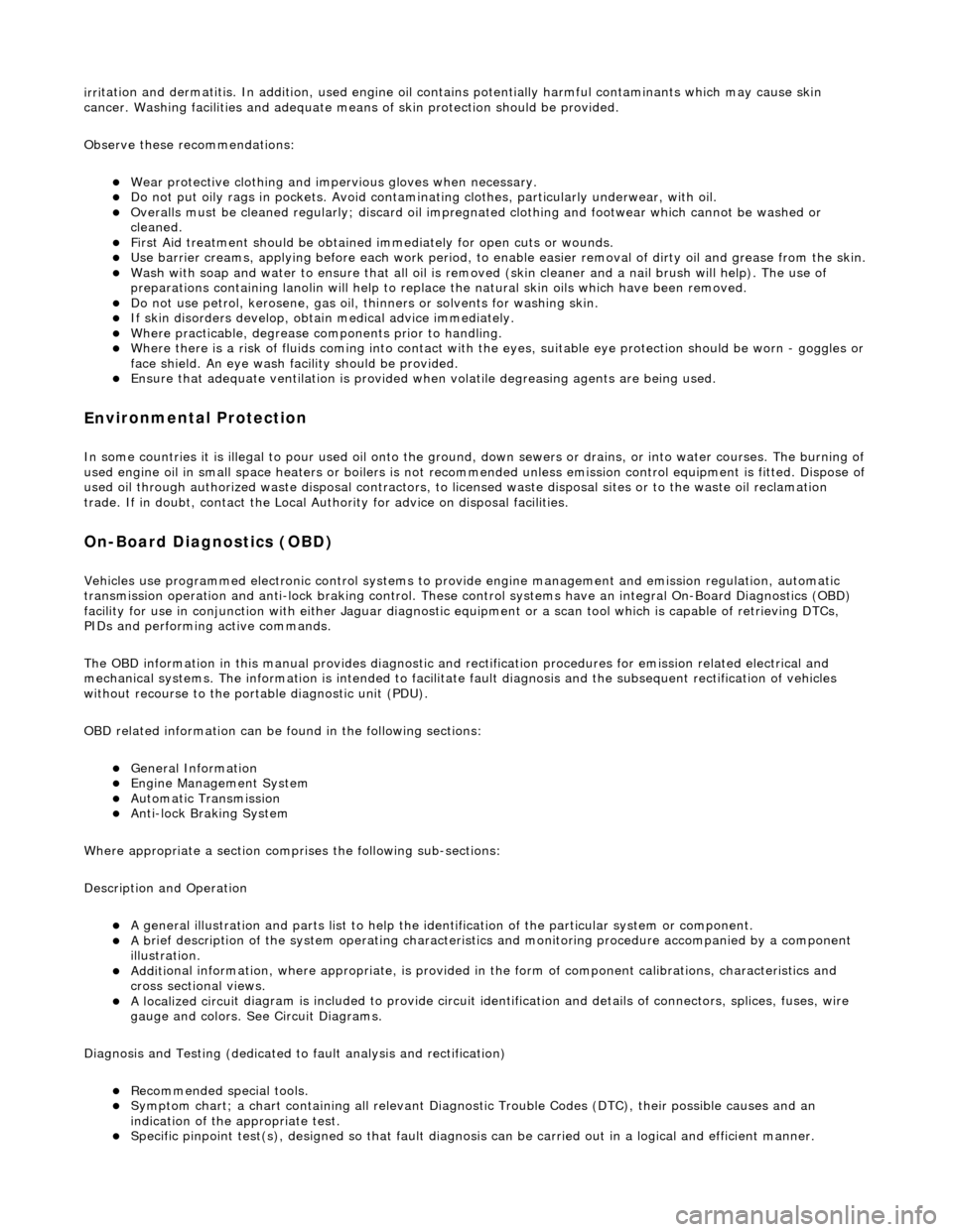
irri
tation and dermatitis. In addition, used engine oil contains potentially harmful contaminants which may cause skin
cancer. Washing facilities and adequate means of skin protection should be provided.
Observe these recommendations:
пЃ¬Wear pro t
ective clothing and impe
rvious gloves when necessary.
пЃ¬Do not put oily
rags in pockets. Avoid contaminat
ing clothes, particularly underwear, with oil.
пЃ¬Overal
ls must be cleaned re
gularly; discard oil impregna ted clothing and footwear wh ich cannot be washed or
cleaned.
пЃ¬Fi rst
Aid treatment should be obtained
immediately for open cuts or wounds.
пЃ¬Use barrier
creams, applying before each work period, to en
able easier removal of dirty oil and grease from the skin.
пЃ¬Wa
sh with soap and water to ensure th
at all oil is removed (skin cleaner and a nail brush will help). The use of
preparations containing lanolin will help to replace the natural skin oils which have been removed.
пЃ¬Do
not use petrol, kerosene, gas oil, th
inners or solvents for washing skin.
пЃ¬If
skin disorders develop, obtain medical advice immediately.
пЃ¬Wh
ere prac
ticable, degrease components prior to handling.
пЃ¬W
h
ere there is a risk of fluids coming into contact with th
e eyes, suitable eye protection should be worn - goggles or
face shield. An eye wash facility should be provided.
пЃ¬Ensure that a
dequate ventilation is provided when volatile degreasing agents are being used.
E
n
vironmental Protection
In so
m
e countries it is illegal to pour used oil onto the ground
, down sewers or drains, or into water courses. The burning of
used engine oil in small space heaters or boilers is not reco mmended unless emission control equipment is fitted. Dispose of
used oil through authorized waste disposal contractors, to licensed waste disposal sites or to the waste oil reclamation
trade. If in doubt, contact the Local Authority for advice on disposal facilities.
On-Board Diagnostics (OBD)
Ve
hicles use programmed electronic control systems to prov
ide engine management and emission regulation, automatic
transmission operation and anti -lock braking control. These control systems ha ve an integral On-Board Diagnostics (OBD)
facility for use in conjunction with either Jaguar diagnostic equipment or a scan t ool which is capable of retrieving DTCs,
PIDs and performing active commands.
The OBD information in this manual provid es diagnostic and rectification procedures for emission related electrical and
mechanical systems. The informat ion is intended to facilitate fault diagnosis and the subsequent rectification of vehicles
without recourse to the portab le diagnostic unit (PDU).
OBD related information can be fo und in the following sections:
пЃ¬General Information
пЃ¬Engine M
anagement System
пЃ¬Auto
matic Transmission
пЃ¬Anti-lock Br
aking System
Where appropriate a section comprises the following sub-sections:
Description and Operation
пЃ¬A ge
neral illustration and parts list to help the identi
fication of the particular system or component.
пЃ¬A b
rief description of the system operating characteristics and monitoring procedure
accompanied by a component
illustration.
пЃ¬Addi ti
onal information, where appropriat
e, is provided in the form of component calibrations, characteristics and
cross sectional views.
пЃ¬A localized circui
t diagram is included to provide circuit iden
tification and details of connectors, splices, fuses, wire
gauge and colors. See Circuit Diagrams.
Diagnosis and Testing (dedicated to fault analysis and rectification)
пЃ¬Recommended special tools. пЃ¬Symptom chart; a ch
art contai
ning all relevant Diagnostic Trouble Code s (DTC), their possible causes and an
indication of the appropriate test.
пЃ¬Sp
ecific pinpoint test(s), de
signed so that fault diagnosis can be carr ied out in a logical and efficient manner.
Page 47 of 2490
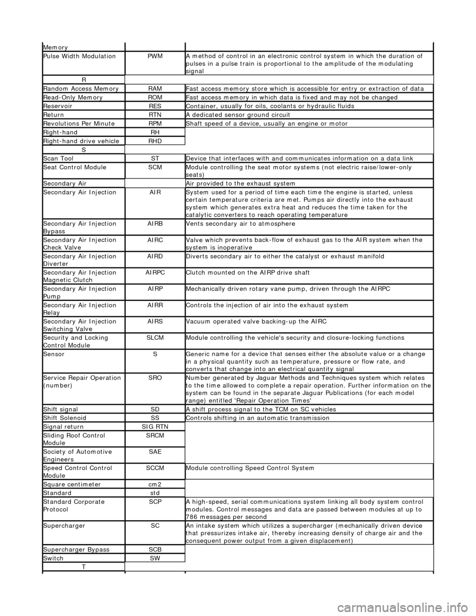
Mem
ory
Pulse Width ModulationPW
M
A
method of control in an electronic co
ntrol system in which the duration of
pulses in a pulse train is proportional to the amplitude of the modulating
signal
R
Ran
dom Access Memory
RAMF
ast access memory store which is accessible for entry or extraction of data
Re
ad-Only Memory
RO
M
F
ast access memory in which data
is fixed and may not be changed
Re
servoir
RESContaine
r, usually for oils,
coolants or hydraulic fluids
Re
turn
RTNA
dedicated sensor ground circuit
R
evolutions Per Minute
RP
M
Shaft speed o
f a device, us
ually an engine or motor
R
ight-hand
RH
Right-hand drive veh
icle
RHD
S
Scan T
ool
STDe
vice that interfaces with and comm
unicates information on a data link
Se
at Control Module
SCMModule
controlling the seat motor systems (not electric raise/lower-only
seats)
Secon
dary Air
Air pro
vided to the exhaust system
Secon
dary Air Injection
AIRSy
stem used for a period of time each
time the engine is started, unless
certain temperature criter ia are met. Pumps air directly into the exhaust
system which generates extra heat and reduces the time taken for the
catalytic converters to reach operating temperature
Secon
dary Air Injection
Bypass
AIRBVents secon
dary air to atmosphere
Secon
dary Air Injection
Check Valve
AIRCValve wh
ich prevents back-flow of exhaust gas to the AIR system when the
system is inoperative
Secon
dary Air Injection
Diverter
AIRDD
iverts secondary air to either
the catalyst or exhaust manifold
Secon
dary Air Injection
Magnetic Clutch
AIRP
C
Clu
tch mounted on the AIRP drive shaft
Secon
dary Air Injection
Pump
AIRPMe
chanically driven rotary vane
pump, driven through the AIRPC
Secon
dary Air Injection
Relay
AIRRCont
rols the injection of air into the exhaust system
Secon
dary Air Injection
Switchin
g Va
lve
AIRSV
acuum operated valve backing-up the AIRC
Secu
rity and Locking
Control Module
SLCMModul
e controlling the vehicle's security and closure-locking functions
SensorSGeneri
c name for a device
that senses either the absolute value or a change
in a physical quantity su ch as temperature, pressure or flow rate, and
converts that change into an electrical quantity signal
Servic
e Repair Operation
(number)
SRONu
mber generated by Jaguar Methods
and Techniques system which relates
to the time allowed to complete a repair operation. Further information on the
system can be found in the separate Jaguar Publications (for each model
range) entitled 'Repair Operation Times'
Shif
t signal
SDA
shift process signal to the TCM on SC vehicles
Shif
t Solenoid
SSControls shi
fting in an automatic transmission
Si
gnal return
SIG RTN
Slidin
g Roof Control
Module
SRCM
Society of Automotive
Engineers
SAE
Speed
Control Control
Module
SCCMModule con
trolling Speed Control System
Square c
entimeter
cm
2
Stan
dard
std
Stan
dard Corporate
Protocol
SCPA
high-speed, serial communications system linking all body system control
modules. Control messages and data ar e passed between modules at up to
786 messages per second
SuperchargerSCAn in
take system which utilizes a supercharger (mechanically driven device
that pressurizes intake air, thereby in creasing density of charge air and the
consequent power output from a given displacement)
Supercharger
Bypass
SCB
SwitchSW
T
Page 48 of 2490
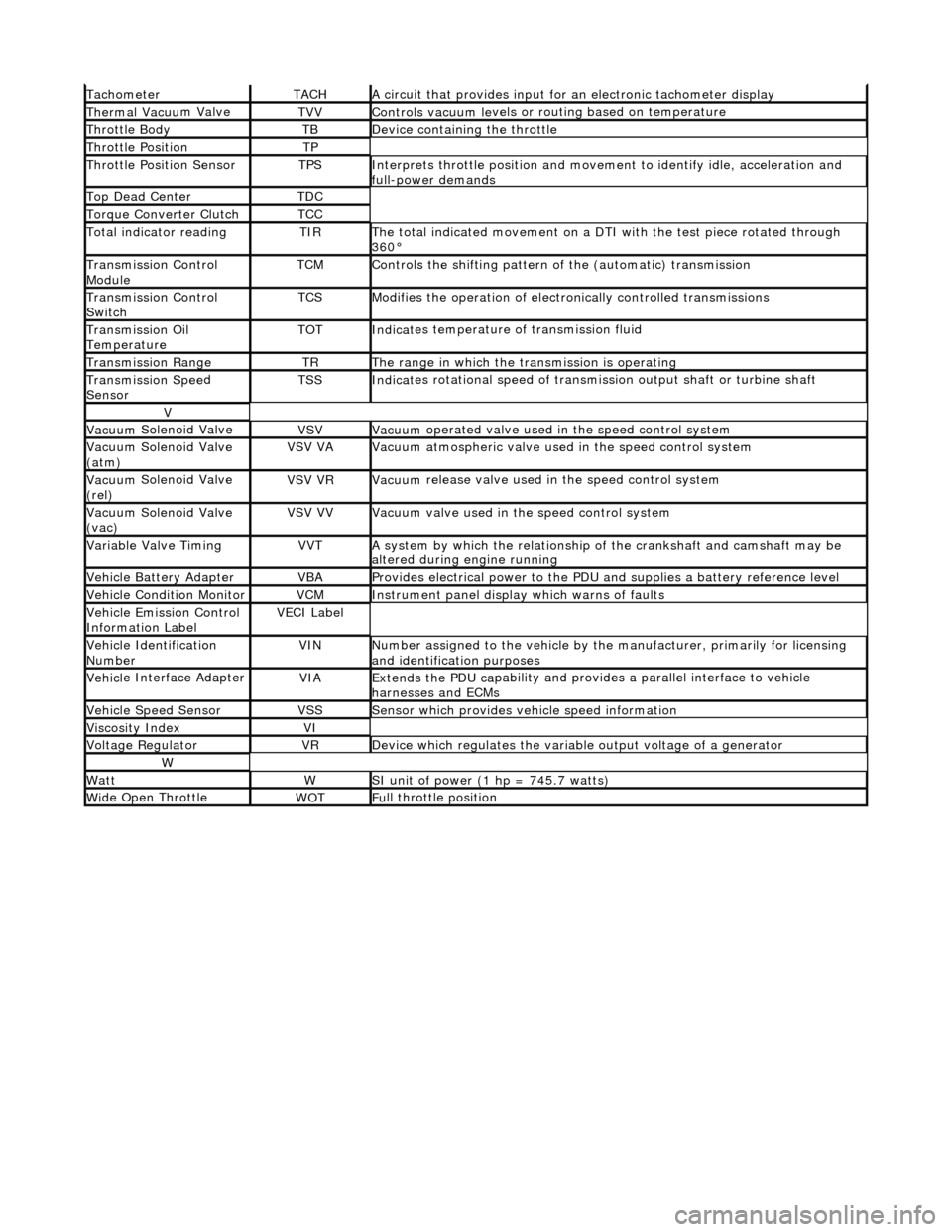
Tacho
meter
TACHA
ci
rcuit that provides input for
an electronic tachometer display
Thermal Vacuu
m Valve
TVVControls vacuum l
e
vels or
routing based on temperature
Throttle
Body
TBDe
vi
ce containing the throttle
Throttl
e
Position
TP
Throttl
e
Position Sensor
TPSInterprets throttl
e
position and movement to iden tify idle, acceleration and
full-power demands
Top Dead CenterTDC
Torque Converter C
lutch
TCC
To
tal
indicator reading
TIRThe t
o
tal indicated movement on a DTI with the test piece rotated through
360В°
Transm
ission Control
Module
TCMControls
the shifting pattern
of the (automatic) transmission
Transm
ission Control
Switch
TCSModifi es
the operation of electronically controlled transmissions
Transmission Oil
TemperatureTOTIndi
cat
es temperature of transmission fluid
Transmission RangeTRThe ran
g
e in which the transmission is operating
Transmission Spe
e
d
Sensor
TSSIndi cat
es rotational speed of transmission output shaft or turbine shaft
V
Vacuu
m
Solenoid Valve
VSVVacuu
m
operated valve used in the speed control system
Vacuu
m
Solenoid Valve
(atm)
VSV VAVacuu m
atmospheric valve used in the speed control system
Vacuu
m
Solenoid Valve
(rel)
VSV VRVacuu m
release valve used in the speed control system
Vacuu
m
Solenoid Valve
(vac)
VSV VVVacuu m
valve used in the speed control system
Variable Valve TimingVVTA
s
ystem by which the relationship of the crankshaft and camshaft may be
altered during engine running
Vehi cl
e Battery Adapter
VBAProvide
s
electrical power to the PDU
and supplies a battery reference level
Vehicl
e Condition Monitor
VCMInst
rum
ent panel display which warns of faults
Ve
hic
le Emission Control
Information Label
VECI Label
Vehi cl
e Identification
Number
VINN u
mber assigned to the vehicle by the manufacturer, primarily for licensing
and identification purposes
Vehi cl
e Interface Adapter
VIAExtends the
PDU ca
pability and provid
es a parallel interface to vehicle
harnesses and ECMs
Vehicle Spe e
d Sensor
VSSSens
or which provides ve
hicle speed information
Viscosity In
dexVI
Voltage RegulatorVRDe
vice which regulates the variable output voltage of a generator
W
Wat
tWSI unit of power (1 hp = 7
45.7 watts)
W
i
de Open Throttle
WO
TFu
ll throttle position
Page 284 of 2490
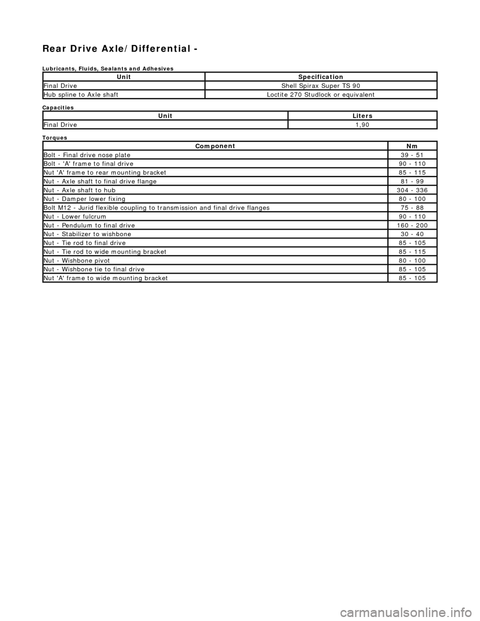
Re
ar Drive Axle/Differential -
Lubric
ants, Fluids, Sealants and Adhesives
Capacities
Torques
UnitSp
ecification
F
i
nal Drive
Shell Sp
irax Supe
r TS 90
Hub s
p
line to Axle shaft
Loct
it
e 270 Studlock or equivalent
UnitLi
t
ers
F
i
nal Drive
1,
90
Com p
onent
Nm
B
ol
t - Final drive nose plate
39
- 51
Bol t
- 'A' frame to final drive
9
0 -
110
Nu
t 'A' f
rame to rear mounting bracket
8
5 -
115
Nu
t -
Axle shaft to final drive flange
81
-
99
Nu
t -
Axle shaft to hub
3
04 -
336
N
u
t - Damper lower fixing
8
0 -
100
Bol
t
M12 - Jurid flexible coupling to
transmission and final drive flanges
75 -
88
N
u
t - Lower fulcrum
9
0 -
110
Nu
t -
Pendulum to final drive
1
60 -
200
N
u
t - Stabilizer to wishbone
30
-
40
N
u
t - Tie rod to final drive
8
5 -
105
Nu
t -
Tie rod to wide mounting bracket
8
5 -
115
Nu
t -
Wishbone pivot
8
0 -
100
N
u
t - Wishbone tie to final drive
8
5 -
105
N
u
t 'A' frame to wide mounting bracket
8
5 -
105
Page 318 of 2490
Comp
onent Tests
Bra
k
e Booster
1.
1. Chec k all
hoses and connections. All unused vacuum connectors should be capped. Hoses and their connections
should be correctly secured and in good condition with no holes and no collapsed areas. Inspect the valve on the
brake booster for damage.
2. 2. Check the hydraulic brake system for leaks or low fluid.
3. 3. With the transmission in PARK, stop the engine and apply the parking brake. Pump the brake pedal several times
to exhaust all vacuum in the system.
4. 4. With the engine switched off and all vacuum in the system exhausted, appl y the brake pedal and hold it down.
Start the engine. If the vacuum system is operating, the brake pedal will tend to move downward under constant
foot pressure. If no motion is felt, the vacuum booster system is not functioning.
5. 5. Remove the vacuum hose from the brake booster. Manifold vacuum should be available at the brake booster end
of the hose with the engine at idle speed and the transm ission in PARK or NEUTRAL. Make sure that all unused
vacuum outlets are correctly capped, hose connectors are correctly secured and vacuum hoses are in good
condition. When it is established that manifold vacuum is available to the brake booster, connect the vacuum hose
to the brake booster and repeat Step 3. If no downward movement of the brake pedal is felt, install a new brake
booster.
6. 6. Operate the engine for a minimum of 10 seconds at a fast idle. Stop the engine and allow the vehicle to stand for
10 minutes. Then, apply th e brake pedal with approximately 89 N ( 20lb) of force. The pedal feel (brake
application) should be the same as that noted with the engine running. If the brake pedal feels hard (no power
assist), install a new valve and then re peat the test. If the brake pedal still feels hard, in stall a new brake booster.
If the brake pedal movement feels spongy, bleed the brak e system. For additional information, refer to General
Procedures in this section.
Bra k
e Master Cylinder
Usual
l
y, the first and strongest
indicator of anything wrong in the brake syst em is a feeling through the brake pedal. In
diagnosing the condition of the brake master cylinder, check pedal feel as evidence of a brake concern. Check for brake
warning lamp illumination and the brake fluid le vel in the brake master cylinder reservoir.
Normal Conditio
ns
The fo
llowing conditions are considered norm
al and are not indications that the brake master cylinder is in need of repair.
пЃ¬New bra
ke systems are designed to produc
e a pedal effort that is not as hard as in the past. Complaints of light
pedal efforts should be compared to the pedal effort s of another vehicle of the same model and year.
пЃ¬The fl
uid level will fall with brake pad wear.
Abnormal Conditions
•
NOTE: Prior to carrying out any diag
nosis, make sure the brake system warning indicator is functional.
Changes in the brake pedal feel or brake pedal travel are in dicators that something could be wrong in the brake system. The
diagnostic procedure and techniques use brake pedal feel, warning indicator illu mination and low brake fluid level as
indicators to diagnosing brake system co ncerns. The following conditions are cons idered abnormal and indicate that the
brake master cylinder is in need of repair:
пЃ¬Brake ped a
l goes down fast. Th
is could be caused by an ex ternal or internal leak.
пЃ¬Brake pedal goes down slowly
. This could be
caused by an internal or external leak.
пЃ¬Brak
e pedal is low or feels spongy. This condition may be ca
used by no fluid in the brake master cylinder, reservoir
Page 696 of 2490
Engine - Flexplate4.0L NA V8 - AJ27/3.2L NA V8 - AJ26
In-vehicle Repair
Removal
Installation
1. Open the engine compartment and fit paint protection sheets.
2. Disconnect the batt ery ground cable.
пЃ¬Remove the battery cover.
3. Remove the Engine Covers, Air Intake Tube, Catalytic
Converters and the Front Muffler. Drain the transmission fluid
and remove the transmission for access.
пЃ¬Refer to Operation 44.20. 01 Transmission Remove, in
Section 307-01A, which includes each of the above
operations.
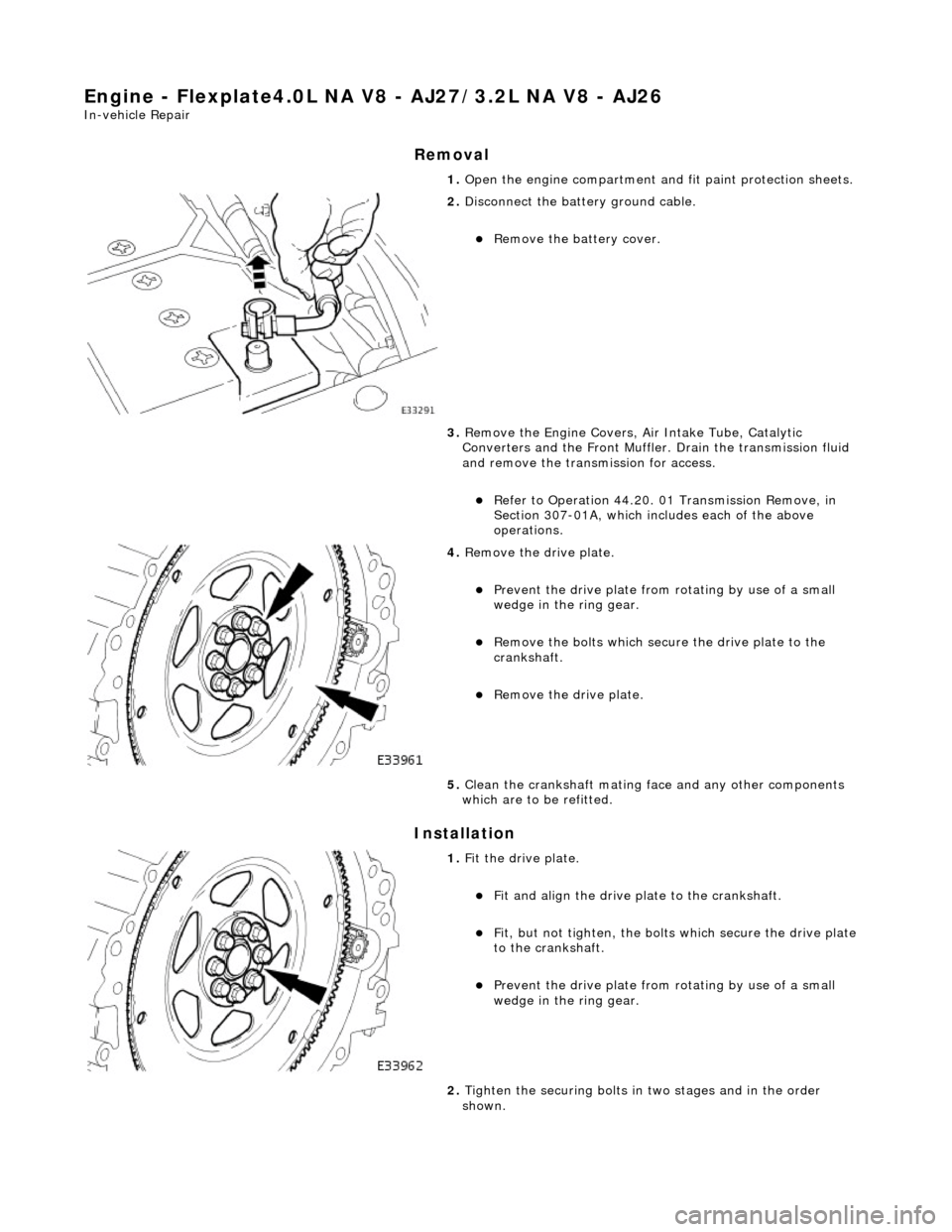
4. Remove the drive plate.
пЃ¬Prevent the drive plate from rotating by use of a small
wedge in the ring gear.
пЃ¬Remove the bolts which secure the drive plate to the
crankshaft.
пЃ¬Remove the drive plate.
5. Clean the crankshaft mating face and any other components
which are to be refitted.
1. Fit the drive plate.
пЃ¬Fit and align the drive plate to the crankshaft.
пЃ¬Fit, but not tighten, the bolt s which secure the drive plate
to the crankshaft.
пЃ¬Prevent the drive plate from rotating by use of a small
wedge in the ring gear.
2. Tighten the securing bolts in two stages and in the order
shown.
Page 697 of 2490

пЃ¬STAGE ONE tighten to 14 - 16 Nm.
3. Tighten the securing bolts in two stages and in the order
shown.
пЃ¬STAGE TWO tighten to 95 - 125 Nm.
4. Refit the Transmission, Catalytic Converters and the Front
Muffler, Air Intake Tube an d Engine Covers. Refill the
transmission with new fluid.
пЃ¬Refer to Operation 44.20. 01 Transmission Install, in
Section 307-01A, which includes each of the above
operations.
5. Remove the paint protection sheets and close the engine
compartment cover.
6. Connect the battery and fit the battery cover.
пЃ¬Refer to the Battery Reconnection Procedure 86.15.15.
Page 698 of 2490
Engine - Flexplate4.0L SC V8 - AJ26
In-vehicle Repair
Removal
Installation
1. Open the engine compartment and fit paint protection sheets.
2. Disconnect the batt ery ground cable.
пЃ¬Remove the battery cover.
3. Remove the Engine Covers, Air Intake Tube, Catalytic
Converters and the Front Muffler. Drain the transmission fluid
and remove the transmission for access.
пЃ¬Refer to Operation 44.20. 01 Transmission Remove, in
Section 307-01B, which includes each of the above
operations.
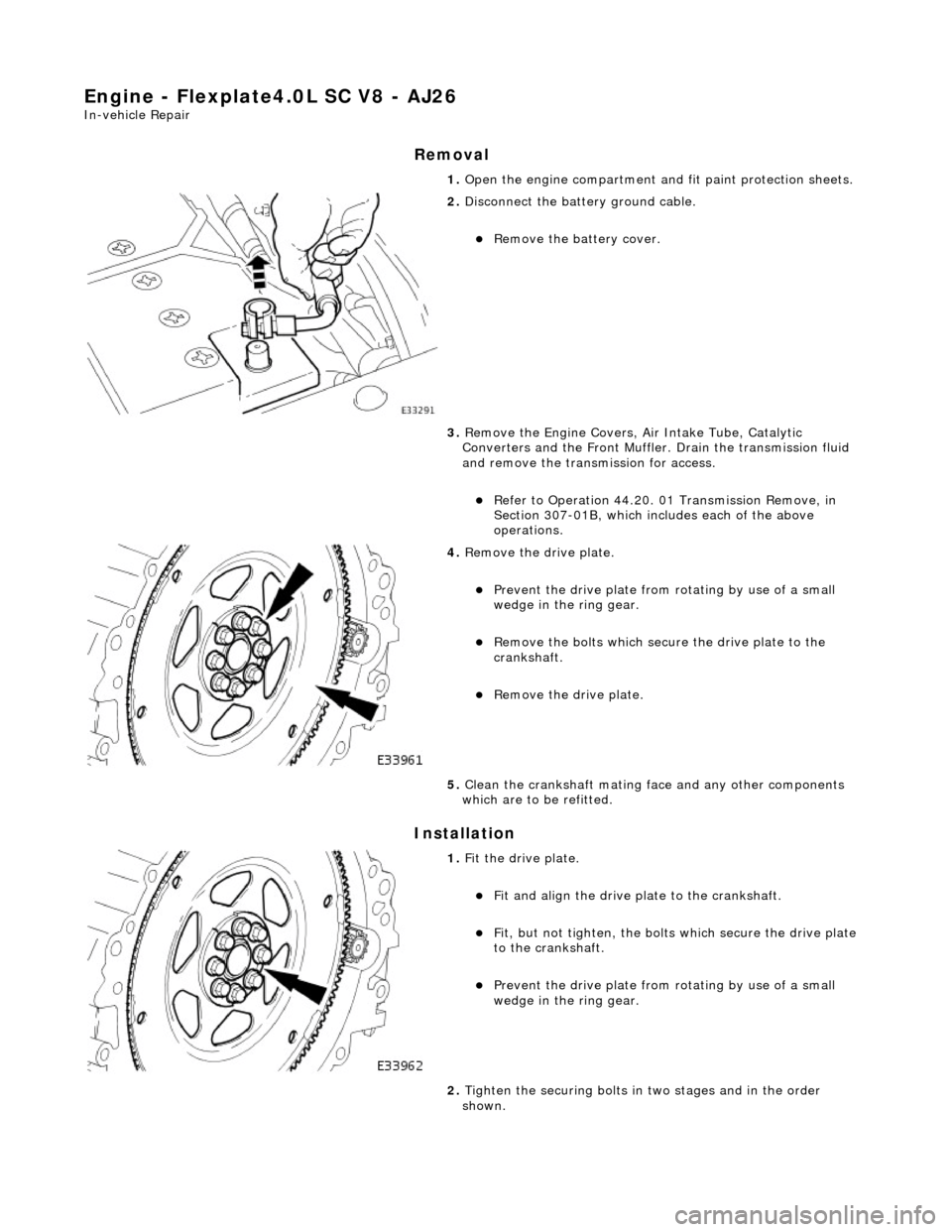
4. Remove the drive plate.
пЃ¬Prevent the drive plate from rotating by use of a small
wedge in the ring gear.
пЃ¬Remove the bolts which secure the drive plate to the
crankshaft.
пЃ¬Remove the drive plate.
5. Clean the crankshaft mating face and any other components
which are to be refitted.
1. Fit the drive plate.
пЃ¬Fit and align the drive plate to the crankshaft.
пЃ¬Fit, but not tighten, the bolt s which secure the drive plate
to the crankshaft.
пЃ¬Prevent the drive plate from rotating by use of a small
wedge in the ring gear.
2. Tighten the securing bolts in two stages and in the order
shown.