ECU JAGUAR X308 1998 2.G Workshop Manual
[x] Cancel search | Manufacturer: JAGUAR, Model Year: 1998, Model line: X308, Model: JAGUAR X308 1998 2.GPages: 2490, PDF Size: 69.81 MB
Page 2206 of 2490

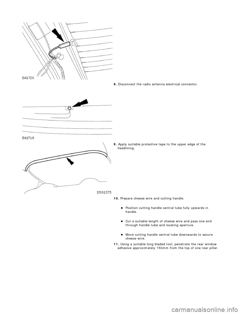
8. Disconnect the radio antenn a electrical connector.
9. Apply suitable protec tive tape to the upper edge of the
headlining.
10. Prepare cheese wire and cutting handle.
Position cutting handle cent ral tube fully upwards in
handle.
Cut a suitable length of ch eese wire and pass one end
through handle tube and locating aperture.
Move cutting handle central tube downwards to secure
cheese wire.
11. Using a suitable long bladed tool, penetrate the rear window
adhesive approximately 150mm fro m the top of one rear pillar.
Page 2214 of 2490

Cut a suitable length of cheese wire and pass one end
through handle tube and locating aperture.
Move cutting handle central tube downwards to secure
cheese wire.
12. Using a suitable long bladed tool, penetrate Betaseal
approximately 150mm from the top of one A pillar.
13. Pass free end of cheese wire through penetration and install
second cutting handle.
14. WARNING: When removing the windshield glass,
personal protection must be worn. Failure to follow this
instruction may result in personal injury.
• CAUTIONS:
Make sure the ch eese wire cannot contact the paintwork
while the the windshield adhesive is being cut. Failure to follow
this instruction may result in damage to the vehicle.
Make sure the cheese wire cannot contact the instrument
panel while the the windshield adhesive is being cut. Failure to
follow this instruction may result in damage to the vehicle.
Make sure the cheese wire passes the Vehicle Identification
Number (VIN) plate on the correct side. Failure to follow this
instruction may result in damage to the component.
When cutting, do not allow ch eese wire to contact edge of
windshield glass as this will crack the windshield glass.
• NOTE: Apply cutting lubricant to the cheese wire frequently
through out the cutting process.
With assistance and exercising care at the corners to avoid
damaging paintwork, cut around the windshield glass
Page 2220 of 2490

Instrument Panel and Console - Audio Unit Housing
Removal and Installation
Removal
Installation
1.
Remove centre console veneer pa nel. Refer to operations in
this section.
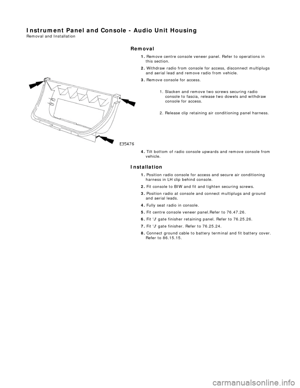
2. Withdraw radio from console for access, disconnect multiplugs
and aerial lead and remo ve radio from vehicle.
3. Remove console for access.
1. Slacken and remove tw o screws securing radio
console to fascia, release two dowels and withdraw
console for access.
2. Release clip retaining air conditioning panel harness.
4. Tilt bottom of radio console upwards and remove console from
vehicle.
1. Position radio console for access and secure air conditioning
harness in LH clip behind console.
2. Fit console to BIW and fit an d tighten securing screws.
3. Position radio at console and connect multiplugs and ground
and aerial leads.
4. Fully seat radio in console.
5. Fit centre console veneer panel.Refer to 76.47.26.
6. Fit 'J' gate finisher retain ing panel. Refer to 76.25.26.
7. Fit 'J' gate finisher . Refer to 76.25.24.
8. Connect ground cable to battery terminal and fit battery cover.
Refer to 86.15.15.
Page 2221 of 2490

Instrument Panel and Console - Climate Control Assembly Housing
Removal and Installation
Removal
Installation
1. Move 'J' gate selector to position 'D.'
2. Remove battery cover and disc onnect ground cable from
battery terminal. Refer to 86.15.19.
3. Remove 'J' gate finish er. Refer to 76.25.24.
4. Remove 'J' gate finisher reta ining plate.Refer to 76.25.26.
5. Remove centre console veneer panel. Refer to 76.47.26.
6. Remove radio and console. Refer to operations in this section.
7. Disconnect air conditioning panel flying lead multiplug (blue)
in LH side of transmission tunnel.
8. Slacken and remove remaining screw securing air
conditioning panel console to BIW.
9. Withdraw air conditioning panel and console for access and
disconnect the harness multiplug behind panel.
10. Remove air conditioning panel from vehicle.
11. Remove panel from console.
1. Fit air conditioning panel to console.
Page 2222 of 2490

2.
Position air conditioning panel and console at centre console
and connect multiplugs.
3. Fully seat air conditioning pa nel and console on BIW bracket
and fit and tighten securing screw.
4. Fit radio and console. Refer to operations in this section.
5. Fit centre console veneer panel. Refer to operations in this
section.
6. Fit 'J' gate surround. Refer to operations in this section.
7. Fit 'J' gate finisher. Refer to operations in this section.
8. Connect ground cable to battery terminal and fit battery cover.
Refer to 86.15.15.
9. Return 'J' gate selector to position 'P'.
Page 2223 of 2490

Instrument Panel and Console - Coin Stowage Compartment
Removal and Installation
Removal
Installation
1.
Slacken and remove screw securing driver stowage
compartment to fascia.
2. Withdraw stowage compartment from fascia and remove from
vehicle.
1. Position driver stowage compartment in fascia recess.
2. Install stowage compartment to fascia securing screw.
Page 2224 of 2490

Instrument Panel and Console - Floor Console
Removal and Installation
Removal
1. Turn ignition switch to posi tion II and apply footbrake.
2. Move gear selector to the the 'D' position. and release
footbrake.
3. Turn ignition switch to position'O'
4. Remove battery cover and disc onnect ground cable from
battery terminal. Refer to 86.15.19.
5. Where fitted, remove centre cons ole rear extension. Refer to
76.25.05.
6. Remove fascia centre veneer panel. Refer to 76.47.06.
7. Using a thin plastic lever, ca refully release the rear air
distribution control grill tang s at top and sides and remove
grill complete with veneer panel and control.
8. Disconnect cigar lighter and ashtray illumination harness
(white) multiplug at RH rear. of console.
9. Slacken and remove the two co nsole rear securing screws.
10. Remove 'J' gate finisher and veneer panel. Refer to 76.25.24
and 76.25.26.
11. Remove fascia centre veneer panel. Refer to 76.47.06.
Page 2225 of 2490

Installation
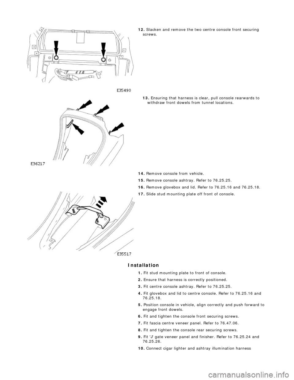
12. Slacken and remove the two ce ntre console front securing
screws.
13. Ensuring that harness is clea r, pull console rearwards to
withdraw front dowels from tunnel locations.
14. Remove console from vehicle.
15. Remove console ashtray. Refer to 76.25.25.
16. Remove glovebox and lid. Refer to 76.25.16 and 76.25.18.
17. Slide stud mounting plate off front of console.
1. Fit stud mounting plate to front of console.
2. Ensure that harness is correctly positioned.
3. Fit centre console ashtray. Refer to 76.25.25.
4. Fit glovebox and lid to centre console. Refer to 76.25.16 and
76.25.18.
5. Position console in vehicle, align correctly and push forward to
engage front dowels.
6. Fit and tighten the consol e front securing screws.
7. Fit fascia centre veneer panel. Refer to 76.47.06.
8. Fit and tighten the console rear securing screws.
9. Fit 'J' gate veneer panel and finisher. Refer to 76.25.24 and
76.25.26.
10. Connect cigar lighter and as htray illumination harness
Page 2227 of 2490

Instrument Panel and Console - Floor Console Ashtray
Removal and Installation
Removal
Installation
1.
Remove battery cover and disc onnect ground cable from
battery terminal. Refer to 86.15.19.
2. Remove center console for access . Refer to operations in this
section.
3. Open ashtray lid and remove cigar lighter.
4. Remove cigar lighter housing.
Remove tape securing harnes s to console underside..
Slacken and remove retaining ring from underside and
remove housing complete with cable.
5. Release bulb housing tangs and withdraw bulb and housing
from underside complete with flying lead.
6. Position console for access, slacken and remove the four
ashtray securing screws and remove ashtray from console.
1. Position ashtray on center console.
2. Fit and tighten the four ashtray securing screws.
3. Fit and fully seat cigar lighter housing in ashtray and fit and
tighten retaining ring.
4. Fit cigar lighter housing and illumination bulb.
5. Tape cables to underside of console.
6. Fit cigar lighter in housing.
7. Close ashtray lid.
8. Fit center console assembly. Refer to 76..
9. Connect multiplug at rear of centre console.
10. Fit centre console rear air distribution control grill.
11. Connect earth cable to battery te rminal and fit battery cover.
Refer to 86.15.15.
Page 2228 of 2490

Instrument Panel and Console - Floor Console Extension
Removal and Installation
Removal
Installation
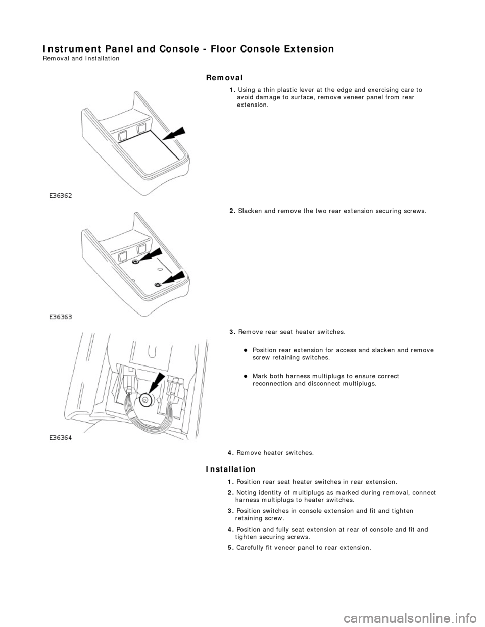
1. Using a thin plastic lever at th e edge and exercising care to
avoid damage to surface, remove veneer panel from rear
extension.
2. Slacken and remove the two rear extension securing screws.
3. Remove rear seat heater switches.
Position rear extension for access and slacken and remove
screw retaining switches.
Mark both harness multip lugs to ensure correct
reconnection and disconnect multiplugs.
4. Remove heater switches.
1. Position rear seat heater switches in rear extension.
2. Noting identity of multiplugs as marked during removal, connect
harness multiplugs to heater switches.
3. Position switches in console extension and fit and tighten
retaining screw.
4. Position and fully seat extension at rear of console and fit and
tighten securing screws.
5. Carefully fit veneer panel to rear extension.