ECU JAGUAR X308 1998 2.G Workshop Manual
[x] Cancel search | Manufacturer: JAGUAR, Model Year: 1998, Model line: X308, Model: JAGUAR X308 1998 2.GPages: 2490, PDF Size: 69.81 MB
Page 2370 of 2490
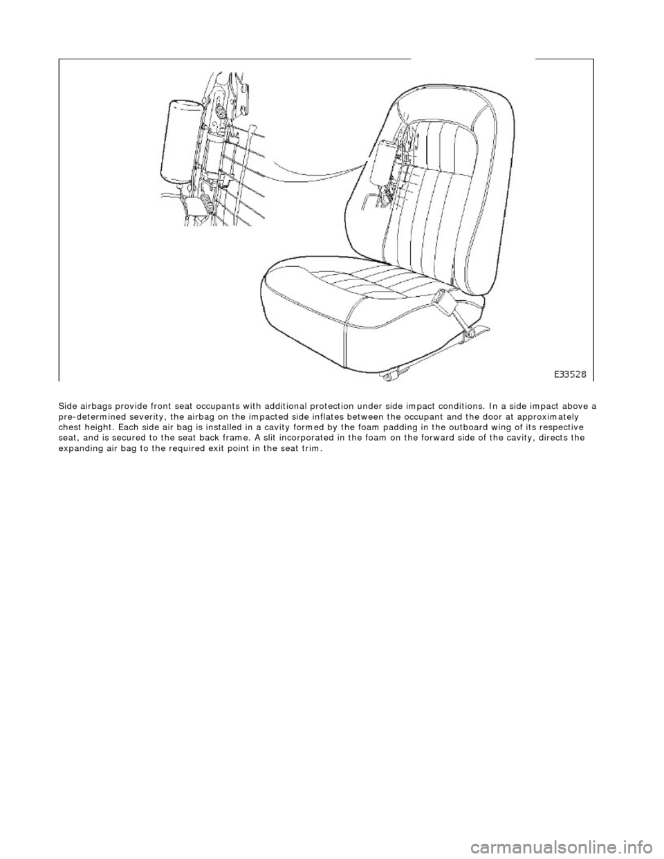
Side airbags provide front seat occupants with additional protection under side impa ct conditions. In a side impact above a
pre-determined severity, the ai rbag on the impacted side inflates between the occupant an d the door at approximately
chest height. Each side air bag is installe d in a cavity formed by the foam padding in the outboard wing of its respective
seat, and is secured to the seat back frame . A slit incorporated in the foam on the forward side of the cavity, directs the
expanding air bag to the required exit point in the seat trim.
Page 2371 of 2490
Supplemental Restraint System - Air Bag Control Module
Removal and Installation
Removal
Installation
1.
WARNING: FOLLOWING DISCONNECTION OF THE
BATTERY, A PERIOD OF AT LEAST ONE MINUTE MUST BE
ALLOWED TO ELAPSE BEFORE ANY WORK IS CARRIED OUT ON
AN AIR BAG SYSTEM COMPONENT.
Remove battery cover and disc onnect ground cable from
battery terminal. Refer to 86.15.19.
2. Remove 'J' gate surroun d. Refer to 76.25.24.
3. Remove centre console veneer panel. Refer to 76.47.26.
4. Remove radio. Re fer to 86.50.03.
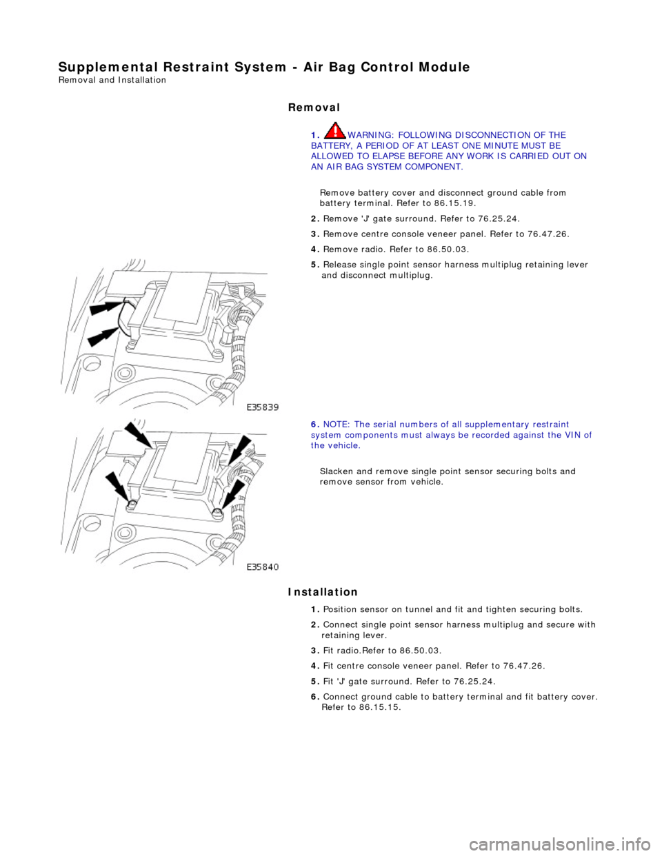
5. Release single point sensor ha rness multiplug retaining lever
and disconnect multiplug.
6. NOTE: The serial num bers of all supplementary restraint
system components must always be recorded against the VIN of
the vehicle.
Slacken and remove single point sensor securing bolts and
remove sensor from vehicle.
1. Position sensor on tunnel and fit and tighten securing bolts.
2. Connect single point sensor harn ess multiplug and secure with
retaining lever.
3. Fit radio.Refer to 86.50.03.
4. Fit centre console veneer panel. Refer to 76.47.26.
5. Fit 'J' gate surround. Refer to 76.25.24.
6. Connect ground cable to battery terminal and fit battery cover.
Refer to 86.15.15.
Page 2372 of 2490
Supplemental Restraint System - Driver Air Bag Module
Removal and Installation
Removal
• WARNINGS:
FOLLOWING DISCONNECTION OF THE BATTERY, A PERIOD OF AT LEAST ONE MINUTE MUST BE ALLOWED TO ELAPSE
BEFORE ANY WORK IS CARRIED OUT ON AN AIR BAG MODULE.
FOLLOWING TEN YEARS IN SERVICE, AN AIR BAG MO DULE MUST BE REMOVED AND DISPOSED OF IN THE
APPROVED MANNER, AND A NEW AIR BAG MUST BE FITTED.
AIR BAGS CONTAIN A CHEMICAL IRRITANT. IF AN AIR BAG IS RENEWED, THE ORIGINAL UNIT MUST BE DISPOSED
OF IN ACCORDANCE WITH CURRENT SAFETY PROCEDURES.
IN THE EVENT OF A FAULT RUPTURING THE 10A BATTERY SUPPLY FUSE (F4 LOCATED IN THE FUSE-BOX AT THE
DRIVER'S END OF THE FASCIA), THE FUSE MUST NOT BE RENEWED UNTIL THE AIRBAG/SRS SYSTEM HAS BEEN DE-
ACTIVATED. FUSES OF ANY OTHER VALUE MUST NEVER BE USED, AS THIS CAN CAUSE DISARM FAILURE.
Installation
1. Remove battery cover and disc onnect ground cable from
battery terminal. Refer to 86.15.19.
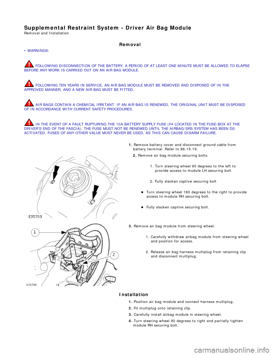
2. Remove air bag module securing bolts.
1. Turn steering wheel 90 degrees to the left to
provide access to module LH securing bolt.
2. Fully slacken captive securing bolt
Turn steering whee l 180 degrees to the right to provide
access to module RH securing bolt.
Fully slacken captive securing bolt.
3. Remove air bag module from steering wheel.
1. Carefully withdraw airbag module from steering wheel
and position for access.
2. Release air bag harness mu ltiplug from retaining clip
and disconnect multiplug.
1. Position air bag module and connect harness multiplug.
2. Fit multiplug onto retaining clip.
3. Carefully install airbag mo dule in steering wheel.
4. Turn steering wheel 90 degrees to right an d partially tighten
module RH securing bolt.
Page 2373 of 2490

5.
Turn steering wheel 90 degrees to left and partially tighten
module LH securing bolt.
6. Repeat steps 3 and 4 to fully ti ghten securing bolts and return
steering wheel to central position.
7. Fit ground cable to battery terminal. Refer to 86.15.15.
Page 2374 of 2490
Supplemental Restraint System - Passenger Air Bag Module
Removal and Installation
Removal
• WARNINGS:
FOLLOWING DISCONNECTION OF THE BATTERY, A PERIOD OF AT LEAST ONE MINUTE MUST BE ALLOWED TO ELAPSE
BEFORE ANY WORK IS CARRIED OUT ON AN AIR BAG MODULE.
FOLLOWING TEN YEARS IN SERVICE, AN AIR BAG MO DULE MUST BE REMOVED AND DISPOSED OF IN THE
APPROVED MANNER, AND A NEW AIR BAG MUST BE FITTED.
AIR BAGS CONTAIN A CHEMICAL IRRITANT. IF AN AIR BAG IS RENEWED, THE ORIGINAL UNIT MUST BE DISPOSED
OF IN ACCORDANCE WITH CURRENT SAFETY PROCEDURES.
IN THE EVENT OF A FAULT RUPTURING THE 10A BATTERY SUPPLY FUSE (F4 LOCATED IN THE FUSE-BOX AT THE
DRIVER'S END OF THE FASCIA), THE FUSE MUST NOT BE RENEWED UNTIL THE AIRBAG/SRS SYSTEM HAS BEEN DE-
ACTIVATED. FUSES OF ANY OTHER VALUE MUST NEVER BE USED, AS THIS CAN CAUSE DISARM FAILURE.
1. Remove battery cover and disc onnect ground cable from
terminal. Refer to 86.15.19.
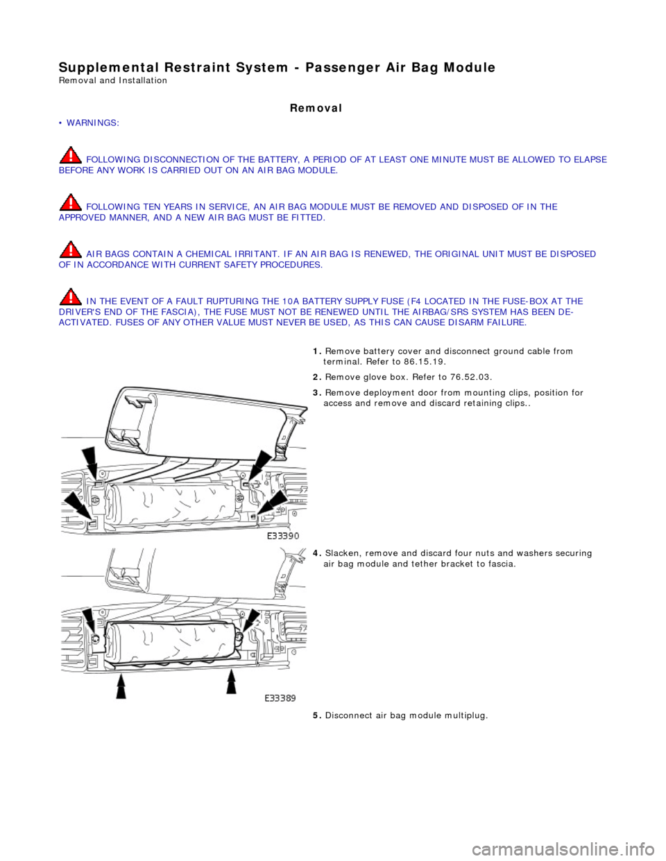
2. Remove glove box. Refer to 76.52.03.
3. Remove deployment door from mounting clips, position for
access and remove and di scard retaining clips..
4. Slacken, remove and discard fo ur nuts and washers securing
air bag module and tether bracket to fascia.
5. Disconnect air bag module multiplug.
Page 2375 of 2490

Installation
• NOTE: The serial numbers of all supplementary restrain t system components must always be recorded against the VIN of
the vehicle.
6. Withdraw air bag module and remove from vehicle.
7. Slacken, remove and discard two bolts securing air bag tether
bracket to air bag module.
1. Position air bag module on teth er bracket and fit and tighten
two new securing bolts.
2. Position air bag module and deployment door mounting
bracket in fascia.
3. Fit and tighten four new nuts and washers securing air bag
Page 2377 of 2490
Supplemental Restraint System - Side Air Bag Module
Removal and Installation
Removal
• WARNINGS:
A SIDE AIR BAG MUST ONLY BE RENEWED IF A FAULT FLAG HAS OCCURRED. IN THE EVENT OF SIDE AIR BAG
DEPLOYMENT DUE TO SIDE IMPACT, THE COMPLETE SEAT MUST BE RENEWED.
FOLLOWING TEN YEARS IN SERVICE, AN AIR BAG MO DULE MUST BE REMOVED AND DISPOSED OF IN THE
APPROVED MANNER, AND A NEW AIR BAG MUST BE FITTED.
FOLLOWING DISCONNECTION OF THE BATTERY, A PERIOD OF AT LEAST FIFTEEN MINUTES MUST BE ALLOWED TO
ELAPSE BEFORE DISCONNECTING THE SINGLE-POINT SENSIN G (SPS) UNIT AND AN ELAPSE OF 2 MINUTES ALLOWED
BEFORE DISCONNECTING ANY OTHER SUPPLEMENTARY RESTRAINT SYSTEM COMPONENT.
AIR BAGS CONTAIN A CHEMICAL IRRITANT. IF AN AIR BAG IS RENEWED, THE DISCARDED UNIT MUST BE DISPOSED
OF IN ACCORDANCE WITH CURRENT SAFETY PROCEDURES.
IN THE EVENT OF A FAULT RUPTURING THE 10A BATTERY SUPPLY FUSE (F4 LOCATED IN THE FUSE-BOX AT THE
DRIVER'S END OF THE FASCIA), THE FUSE MUST NOT BE RENEWED UNTIL THE AIRBAG/SRS SYSTEM HAS BEEN DE-
ACTIVATED. FUSES OF ANY OTHER VALUE MUST NEVER BE USED, AS THIS CAN CAUSE DISARM FAILURE.
1. Remove battery cover and disc onnect ground cable from
battery terminal. Refer to 86.15.19.
2. Remove seat from vehi cle. Refer to 76.70.01.
3. Remove seat back fini sher. Refer to 76.70.09.
4. Partially remove squab cover and foam pad for access. Refer to
76.70.15
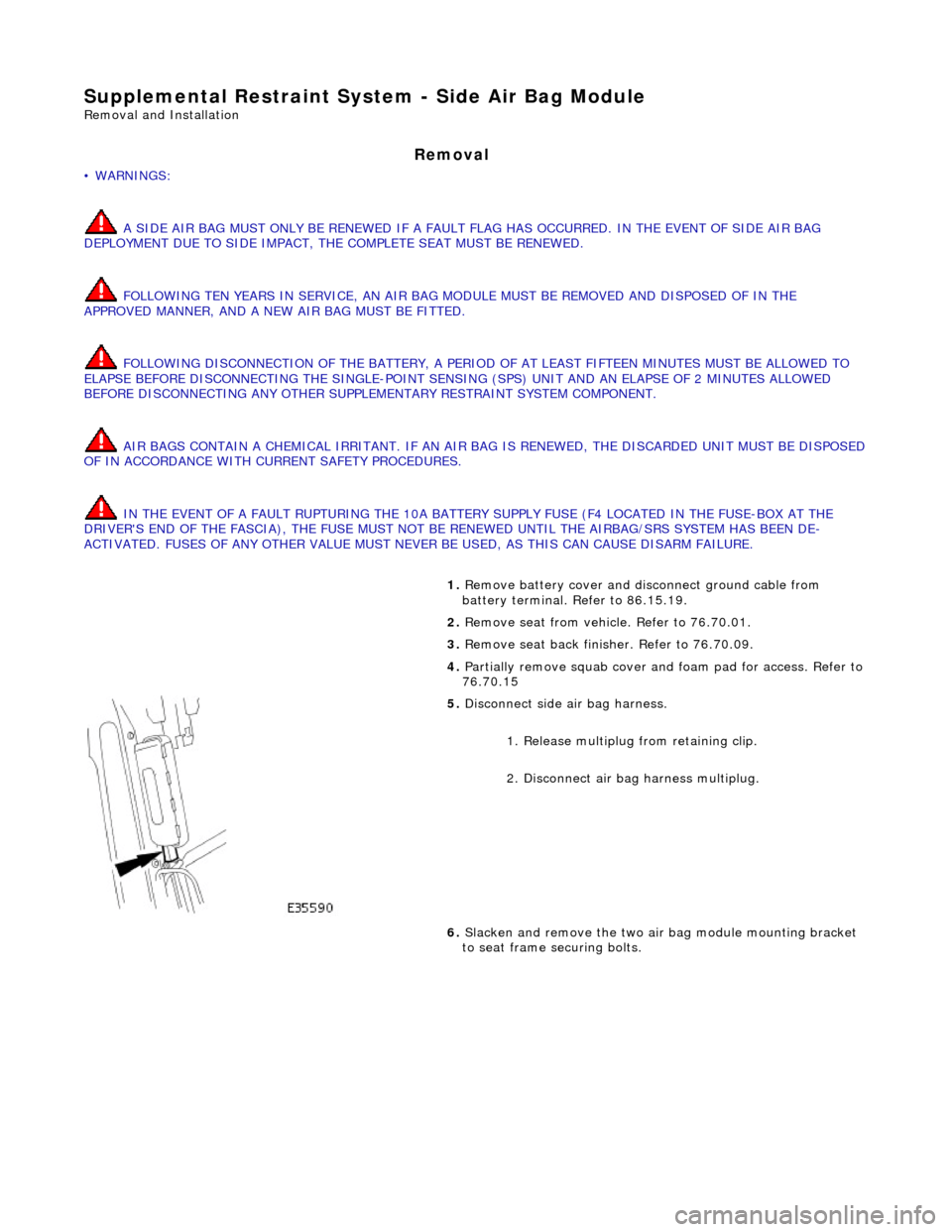
5. Disconnect side air bag harness.
1. Release multiplug from retaining clip.
2. Disconnect air ba g harness multiplug.
6. Slacken and remove the two air bag module mounting bracket
to seat frame securing bolts.
Page 2378 of 2490

Installation
7. Remove air bag module from seat and arrange for disposal in
approved manner.
1. CAUTION: Side air bags are de dicated to either LH or RH
seat installation. When the air bag module is installed, the
multiplug connector must face the seat base.
Position air bag module on the seat frame ensuring that harness
connector faces the seat base.
2. Fit and tighten the securing bolts.
3. Connect the air bag harness mult iplug and fit multiplug onto
retaining clip.
4. CAUTIONS:
Hog rings removed during the following procedure must not
be re-used. Do not commence the following procedure unless new hog rings are availabl e. Use of used or non-Jaguar parts can
impair air bag deployment and cause serious personal injury.
Hog ring pliers must be used to install new hog rings. Use
of ordinary pliers will result in ring deformation, leading to
possible failure and personal in jury during airbag deployment.
Fit the seat squab cover. Refer to 76.70.15.
5. Fit the seat back finisher. Refer to 76.70.09.
6. Connect ground cable to battery terminal and fit battery cover.
Refer to 86.15.15.
Page 2379 of 2490
Supplemental Restraint System - Side Impact Sensor
Removal and Installation
Removal
• WARNINGS:
FOLLOWING DISCONNECTION OF THE BA TTERY, A PERIOD OF AT LEAST FIFTEEN MINUTES MUST BE ALLOWED TO
ELAPSE BEFORE DISCONNECTING THE SINGLE-POINT SENSING (SPS) UNIT.
IN THE EVENT OF A FAULT RUPTURING THE 10A BATTER Y SUPPLY FUSE (F4 LOCATED IN THE FUSE-BOX AT THE
DRIVER'S END OF THE FASCIA), THE FUSE MUST NOT BE RENEWED UNTIL THE AIRBAG/SRS SYSTEM HAS BEEN DE-
ACTIVATED. FUSES OF ANY OTHER VALUE MUST NEVER BE USED, AS THIS CAN CAUSE DISARM FAILURE.
Installation
1. Remove battery cover and disconnect ground cable from battery
terminal. Refer to 86.15.19.
2. Remove'B' post trim pa d. Refer to 76.13.08.
3. Remove seat belt upper anchor and seat belt guide. Refer to
76.73.10
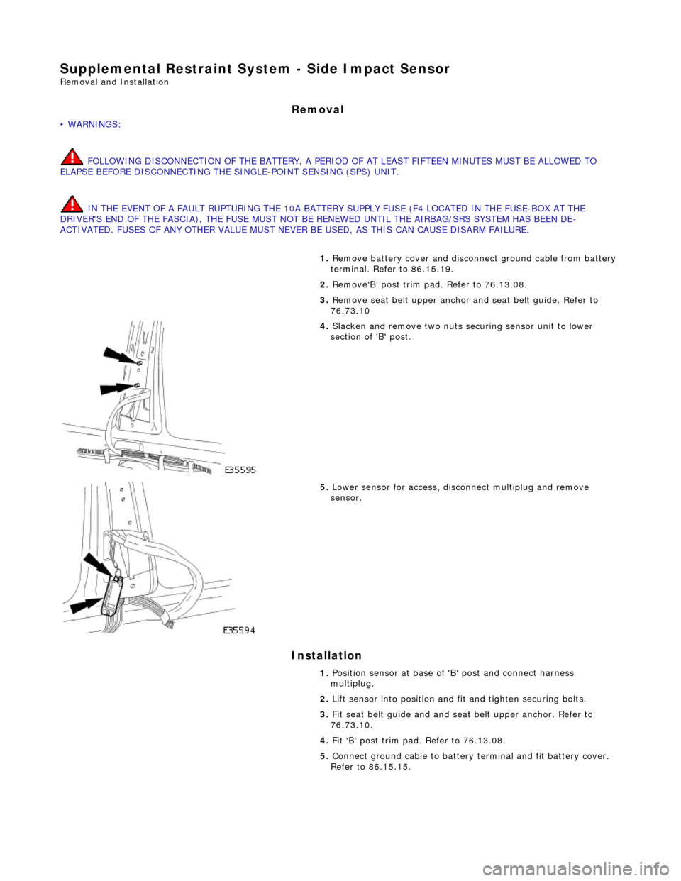
4. Slacken and remove two nuts securing sensor unit to lower
section of 'B' post.
5. Lower sensor for access, disco nnect multiplug and remove
sensor.
1. Position sensor at base of 'B' post and connect harness
multiplug.
2. Lift sensor into position and fit and tighten securing bolts.
3. Fit seat belt guide and and seat belt upper anchor. Refer to
76.73.10.
4. Fit 'B' post trim pad. Refer to 76.13.08.
5. Connect ground cable to battery terminal and fit battery cover.
Refer to 86.15.15.
Page 2393 of 2490
Panel Surface Preparation
ALIGNING AND WELDING PANELS
• NOTE: Observe all appropriate safety procedures.
Apply appropriate sealer or joint preparation.
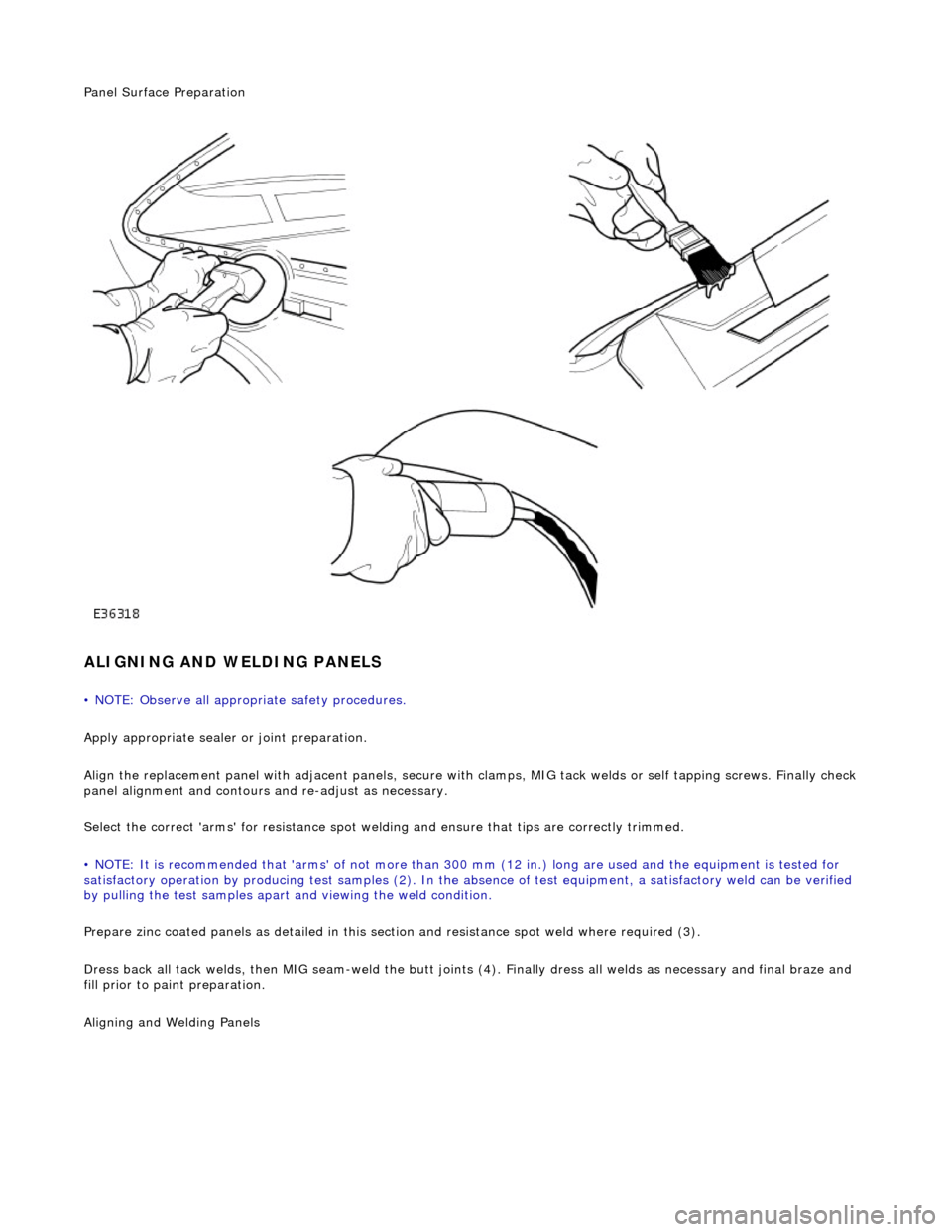
Align the replacement panel with adjacent panels, secure with clamps, MIG tack welds or self tapping screws. Finally check
panel alignment and contours and re-adjust as necessary.
Select the correct 'arms' for resistance spot welding and ensure that tips are correctly trimmed.
• NOTE: It is recommended that 'arms' of not more than 300 mm (12 in.) long ar e used and the equipment is tested for
satisfactory operation by producing test samples (2). In the ab sence of test equipment, a satisfactory weld can be verified
by pulling the test sa mples apart and viewing the weld condition.
Prepare zinc coated panels as detailed in this section and resistance spot weld where required (3).
Dress back all tack welds, then MIG seam-weld the butt joints (4). Finally dress all welds as necessary and final braze and
fill prior to paint preparation.
Ali
gning and Welding Panels