303-14 JAGUAR X308 1998 2.G Workshop Manual
[x] Cancel search | Manufacturer: JAGUAR, Model Year: 1998, Model line: X308, Model: JAGUAR X308 1998 2.GPages: 2490, PDF Size: 69.81 MB
Page 716 of 2490

Tighten the locknut without altering the setting or
introducing twist into the cable outer
Check the kickdown setting using the PDU. For scan tool
procedure, refer to 303-14 , Throttle cable, Renew
21. Reconnect the multi-plugs to the throttle body.
1. Connect the throttle body motor multi-plug.
2. Connect the two potentiometer multi-plugs, one each side of the throttle.
3. Connect the vacuum pipe elbow to the throttle
actuator.
22. Fit the intake tube / air flow meter / air cleaner cover
assembly.
1. Fit a new rubber seal; air in take tube to throttle body.
2. Fit the intake tube / air flow meter / air cleaner cover
assembly.
23. Reconnect the air cleaner cover.
1. Fit the five clips which secure the air cleaner cover.
24. Connect the intake tube to the throttle body.
1. Connect the intake tube to the throttle body.
2. Fit the two bolts which secure the intake tube to the throttle body.
Page 726 of 2490

11. Reconnect the multi-plug, located on the bracket under the
left side of th e throttle body.
12. Connect the coolant hoses to the throttle body.
Remove the blanking plugs from the hoses.
Connect the coolant feed hose and secure with the clip.
Connect the coolant return hose and secure with the clip.
13. CAUTION: Under no circumstances may the quadrant be held clear of the throttle stop by cable tension
Refit the throttle cable and ensure that there is neither tension
nor slack in the cable
Tighten the locknut without altering the setting or
introducing twist into the cable outer
Check the kickdown setting us ing the PDU. For scan tool
procedure, refer to 303-14 , Throttle cable, Renew
14. Reconnect the multi-plugs to the throttle body.
1. Connect the throttle body motor multi-plug.
2. Connect the two potentiometer multi-plugs, one each side of the throttle.
Page 1107 of 2490

Intake Air Distribution and Filtering - Intake Air Distribution and Filtering
Description an
d Operation
I
ntake Air Distribution and Filtering - Normally Aspirated Vehicles
Air Intake Asse
mbly
The air cleaner assembly consists of a two piece box containing the air filter, an airflow/temperature unit and the air intake
duct which connects to the top of the throttle assembly. The en gine full load breather feeds into the intake duct from the
bank 1 camshaft cover. A tuned stub on the ai r intake duct reduces the intake noise level.
Mass Air Flow and Temperature Sensors
The intake air is monitored by the Mass Air Flow (MAF) sensor assembly which is fitted at the outlet of the air filter
assembly. Two sensors are incorporated in the MAF sensor assembly, measuring air flow and temperature (temperature
sensor arrowed); both sensors provide anal ogue signal inputs to the engine control module (ECM) and are further described
in Section 303-14.
Page 1395 of 2490

and/or increased performance as appropriate.
Serial Communications Interfaces
Controller Area Network (CAN)
The TCM is an integral part of the CAN system which facilita tes the interchange of real-time data between control modules
and sensors; refer to 303-14 fo r a full description of CAN.
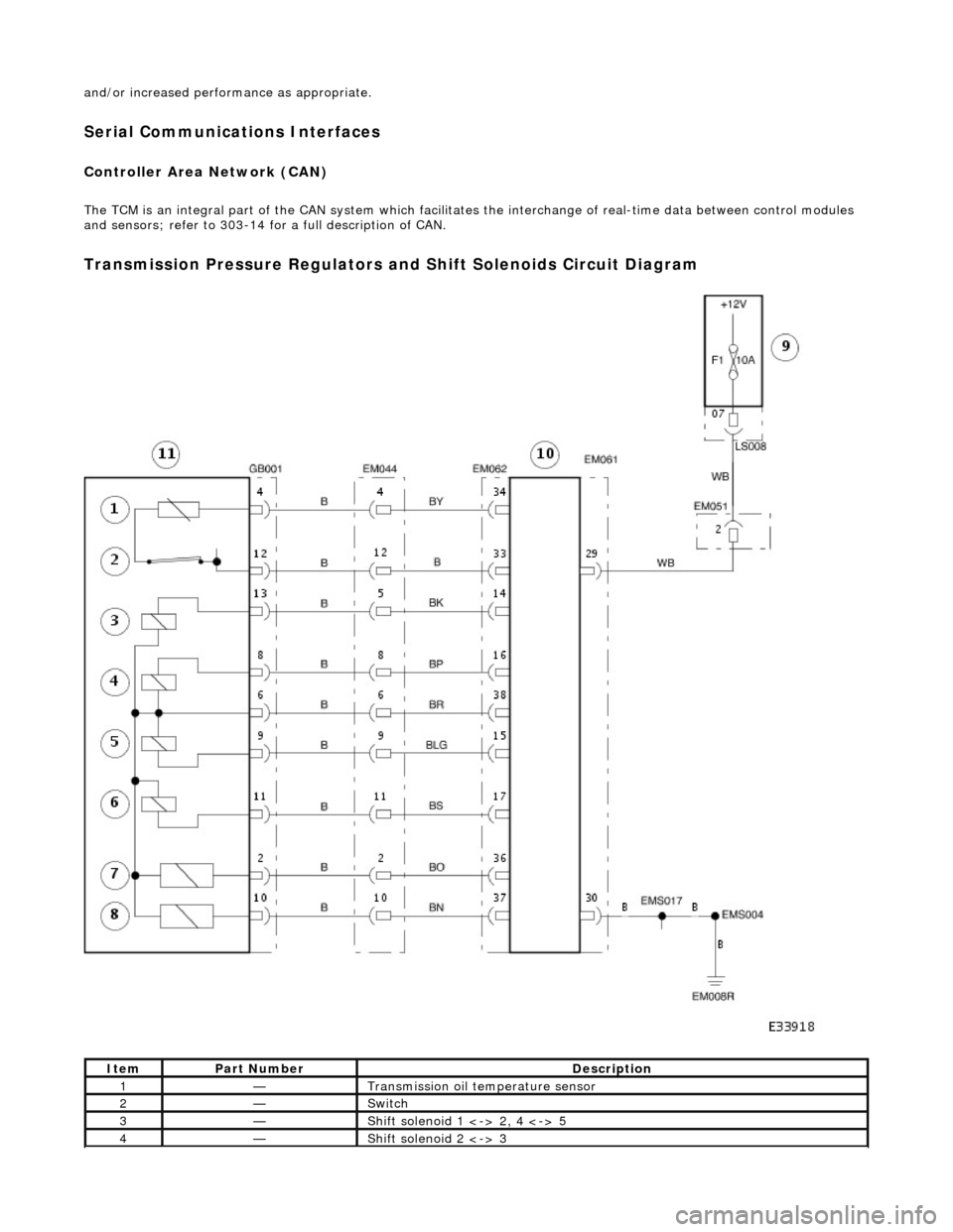
Transmission Pressure Regulators and Shift Solenoids Circuit Diagram
ItemPart NumberDescription
1—Transmission oil temperature sensor
2—Switch
3—Shift solenoid 1 <-> 2, 4 <-> 5
4—Shift solenoid 2 <-> 3