Mass air flow JAGUAR X308 1998 2.G Workshop Manual
[x] Cancel search | Manufacturer: JAGUAR, Model Year: 1998, Model line: X308, Model: JAGUAR X308 1998 2.GPages: 2490, PDF Size: 69.81 MB
Page 16 of 2490

В В В В В В В В В В В В В В В В В В В В KnockВ Sensor В (KS) В RH В (18.30.93) В
В В В В В В В В В В В В В В В В В В В В
VariableВ Camshaft В Timing В (VCT) В Oil В Co ntrol
В
Solenoid В (18.30.90) В
В
В В В В В В В В
307: В Automatic В Transmission/Transaxle В
В
В В В В В В В В В В В В 307‐01A :В Automatic В Transmission/Transaxle  ‐ 3.2L В NA В V8  ‐ AJ26/4.0LВ NAВ V8  ‐ AJ27 В
В В В В В В В В В В В В В В В В Specification В
В В В В В В В В В В В В В В В В Description В and В Operation В
В В В В В В В В В В В В В В В В В В В В TransmissionВ DescriptionВ
В В В В В В В В В В В В В В В В Diagnosis В and В Testing В
В В В В В В В В В В В В В В В В В В В В DiagnosticВ Strategy В
В В В В В В В В В В В В В В В В GeneralВ Procedures В
В В В В В В В В В В В В В В В В В В В В TransmissionВ FluidВ Drain В and В Refill В (44.24.02) В
                In‐Ve
hicle В Repair В
В В В В В В В В В В В В В В В В В В В В ElectronicВ PressureВ ControlВ (EPC)В Solenoid В (44.15.51) В
В В В В В В В В В В В В В В В В В В В В ExtensionВ Housing В Seal В (44.20.18) В
В В В В В В В В В В В В В В В В В В В В ExtensionВ Housing В O ‐Ring В Seal В (44.20.19) В
В В В В В В В В В В В В В В В В В В В В MainВ ControlВ ValveВ BodyВ (44.40.01) В
В В В В В В В В В В В В В В В В В В В В OutputВ Shaft В Speed В (OSS) В Sensor В (44.15.41) В
В В В В В В В В В В В В В В В В В В В В ShiftВ Solenoids В (SS) В (44.15.50) В
В В В В В В В В В В В В В В В В В В В В TransmissionВ ControlВ Module В (TCM) В (44.15.32) В
В В В В В В В В В В В В В В В В В В В В TransmissionВ FluidВ Filter В (44.24.07) В
В В В В В В В В В В В В В В В В В В В В TransmissionВ Fl
uid В Pan В (44.24.04) В
В В В В В В В В В В В В В В В В В В В В TransmissionВ FluidВ Pan В Gasket В (44.24.05) В
В В В В В В В В В В В В В В В В В В В В TransmissionВ InternalВ Wiring В Harness В (44.15.35) В
В В В В В В В В В В В В В В В В В В В В TransmissionВ InternalВ Wiring В Harness В Electrical В ConnectorВ O‐Ring В SealsВ В
В В В В В В В В В В (44.24.20)В
В В В В В В В В В В В В В В В В В В В В TransmissionВ RangeВ (TR)В Sensor В
В В В В В В В В В В В В В В В В В В В В TransmissionВ SupportВ InsulatorВ (12.45.04) В
В В В В В В В В В В В В В В В В В В В В TurbineВ Shaft В Speed В (TSS) В Sensor В (44.15.40) В
В В В В В В В В В В В В В В В В RemovalВ
В В В В В В В В В В В В В В В В В В В В TransmissionВ (44.20.01)В
В В В В В В В В В В В В В В В В Disassembly В and В AssemblyВ ofВ Subassemblies В
В В В В В В В В В В В В В В В В В В В В InputВ Sh
aft В Seal В (44.32.07) В
В В В В В В В В В В В В В В В В В В В В TorqueВ Converter В (44.17.07) В
В В В В В В В В В В В В В В В В Installation В
В В В В В В В В В В В В В В В В В В В В TransmissionВ (44.20.01)В
Mass
В
Airflow
В
Sen s
or
В
Knock
В Sensor
В (KS)
В LH
В (18.30.92)
В
Page 45 of 2490
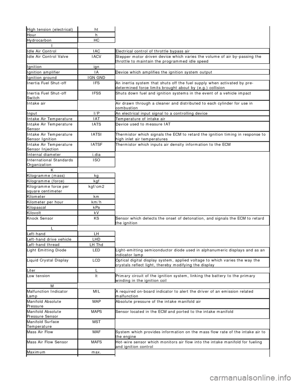
High
tension (electrical)
ht
Hourh
Hydro
carbon
HC
I
Idl
e Air Control
IACEl
ectrical control of throttle bypass air
Idl
e Air Control Valve
IACVStepper motor dri
ven device which vari
es the volume of air by-passing the
throttle to maintain the programmed idle speed
Ignitionign
Ignition am
plifier
IAD
evice which amplifies the i
gniti
on system output
Ignition groundIGN GND
In
ertia Fuel Shut-off
IFSAn
inertia system that shuts off the fuel supply when activated by pre-
determined force limits brough t about by (e.g.) collision
In
ertia Fuel Shut-off
Switch
IFSSShut
s down fuel and ignition systems in the event of a vehicle impact
Inta
ke air
Air drawn t
hrough a cleaner and distri
buted to each cylinder for use in
combustion
InputI/PAn
electrical input signal to a controlling device
Inta
ke Air Temperature
IATTem
perature of intake air
Inta
ke Air Temperature
Sensor
IATSDe
vice used to measure IAT
Inta
ke Air Temperature
Sensor Ignition
IATSITherm
istor which signals the ECM to retard
the ignition timing in response to
high inlet air temperatures
Inta
ke Air Temperature
Sensor Injection
IATSFTher
mistor which inputs air density information to the ECM
Internal diameteri.
dia
Inte
rnational Standards
Organization
ISO
K
Kilogramme (mass)kg
Kilogram
me (force)
kg
f
Ki
logramme force per
square centimeter
kg
f/cm2
Kilom
eter
km
Ki
lometer per hour
km
/h
Kilopasc
al
kP
a
KilovoltkV
Knock
Sensor
KSSens
or which detects the onset of detonation, and signals the ECM to retard
the ignition
L
Le
ft-hand
LH
Left-hand drive veh
icle
LHD
Le
ft-hand thread
LH Thd
Ligh
t Emitting Diode
LEDLigh
t-emitting semiconductor diode used
in alphanumeric displays and as an
indicator lamp
Liqu
id Crystal Display
LCDOp
tical digital display system, applied voltage to which varies the way the
crystals reflect light, thereby modifying the display
LiterL
Low ten
sion
ltPrim
ary circuit of the ignition system, linking the battery to the primary
winding in the ignition coil
M
Malfu
nction Indicator
Lamp
MILA
required on-board indicator to aler
t the driver of an emission related
malfunction
Mani
fold Absolute
Pressure
MAPAbsolute pressure o
f the intake manifold air
Mani
fold Absolute
Pressure Sensor
MAPSSensor loca
ted in the ECM and
ported to the intake manifold
Manifol
d Surface
Temperature
MST
Mass Ai
r Flow
MAFSy
stem which provides inform
ation on the mass flow rate of the intake air to
the engine
Mass Ai
r Flow Sensor
MAFSHot-wi
re sensor which monitors air flow
into the intake manifold for fueling
and ignition control
Maxim
um
max.
Page 525 of 2490
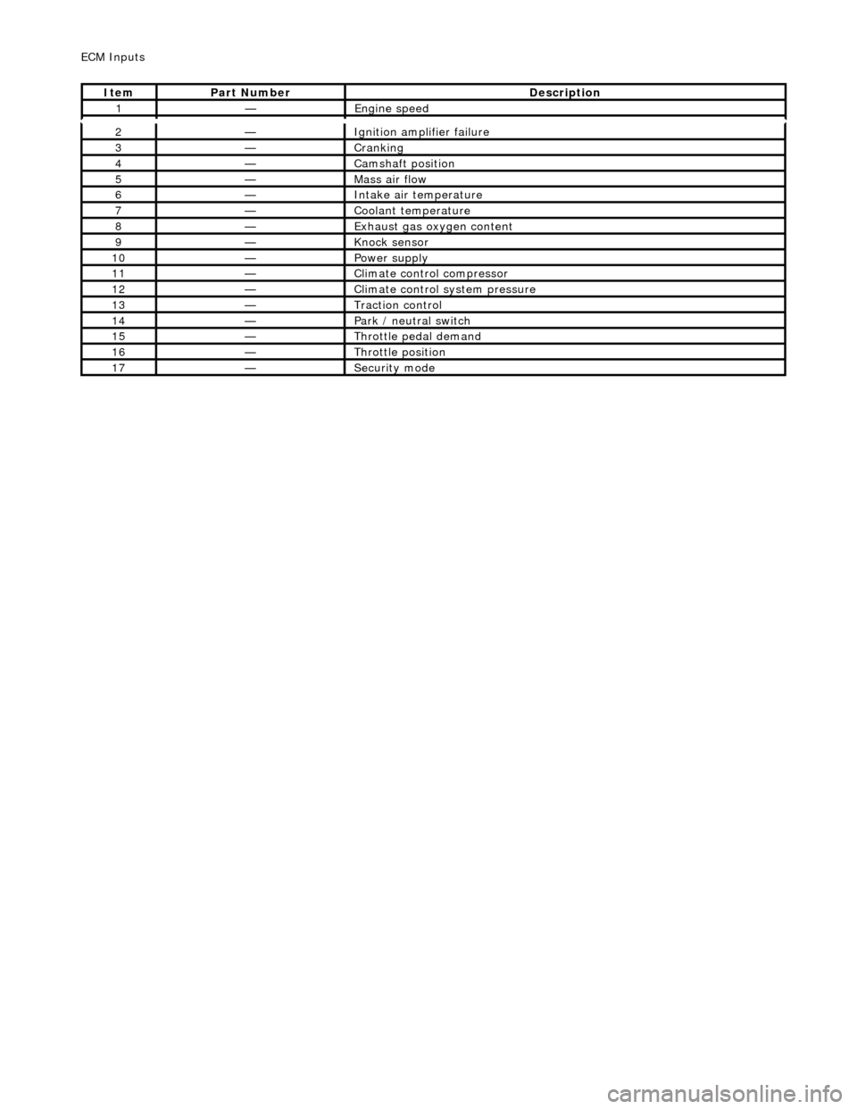
2—Ignition ampl
ifier failure
3—Crankin
g
4—Camshaft position
5—Mass ai
r flow
6—Inta
ke air temperature
7—Coo
lant temperature
8—Exhaus
t gas oxygen content
9—Knock
sensor
10—Power supply
11—Cl
imate control compressor
12—Cli
mate control system pressure
13—Traction contr
ol
14—Park / neutral
switch
15—Throttle pedal demand
16—Thro
ttle position
17—Securi
ty mode
ECM In
puts
It
em
Par
t Number
De
scription
1—Engine
speed
Page 527 of 2490
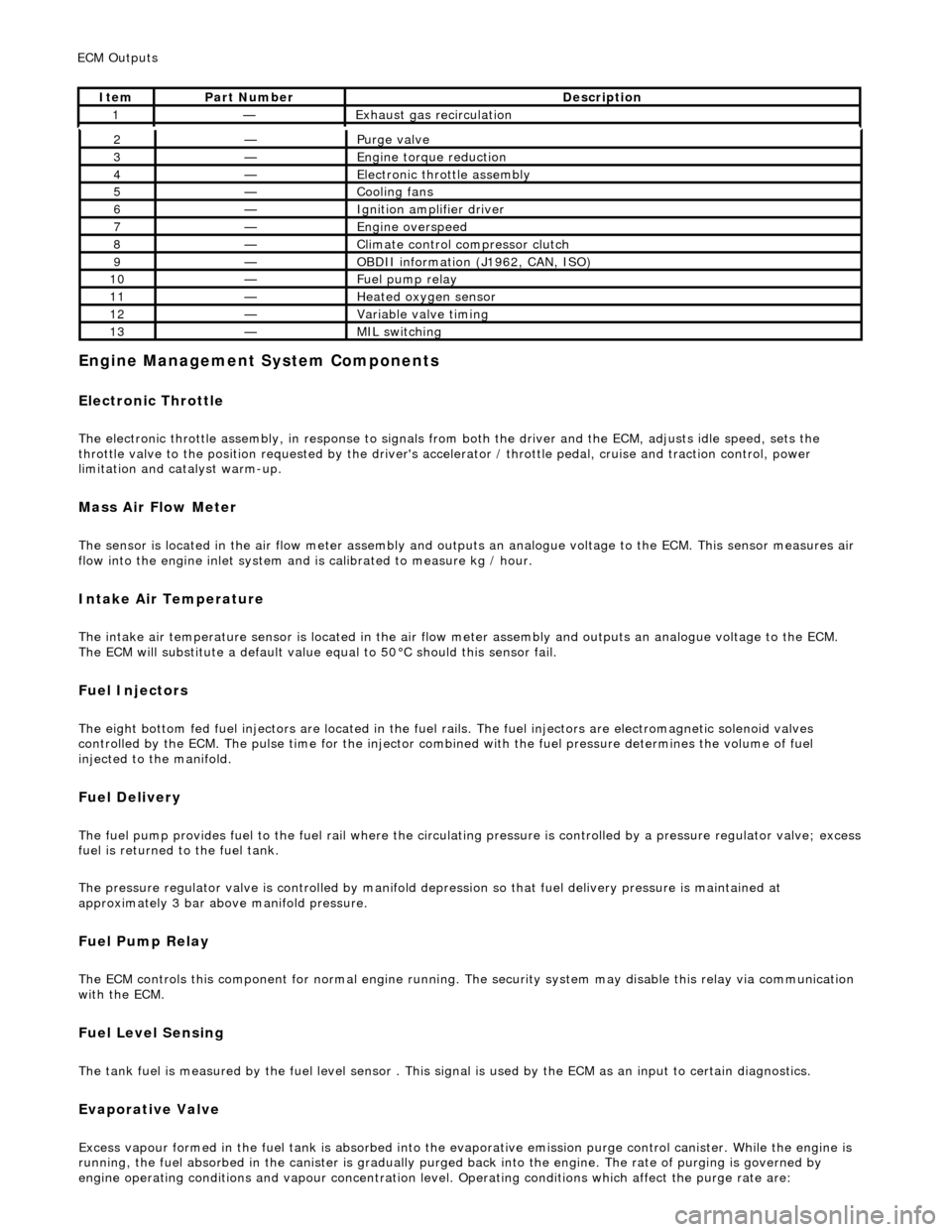
E
ngine Management System Components
Electronic Throt
tle
The
electronic throttle assembly, in resp
onse to signals from both the driver and the ECM, adjusts idle speed, sets the
throttle valve to the position requested by the driver's accelerator / throttle pedal, cruise and traction control, power
limitation and catalyst warm-up.
Mass
Air Flow Meter
The sensor i
s located in the air flow mete
r assembly and outputs an analogue voltag e to the ECM. This sensor measures air
flow into the engine inlet system and is calibrated to measure kg / hour.
In
take Air Temperature
Th
e intake air temperature sensor is loca
ted in the air flow meter assembly and outputs an analogue voltage to the ECM.
The ECM will substitute a default value eq ual to 50В°C should this sensor fail.
Fuel Injectors
The eigh
t bottom fed fuel injectors are located in the fuel rails. Th
e fuel injectors are electromagnetic solenoid valves
controlled by the ECM. The pulse time for the injector combined with the fuel pr essure determines the volume of fuel
injected to the manifold.
Fue
l Delivery
The fu
el pump provides fuel to the fuel rail where the circulat
ing pressure is controlled by a pressure regulator valve; excess
fuel is returned to the fuel tank.
The pressure regulator valve is controlled by manifold depression so that fuel delivery pressure is maintained at
approximately 3 bar above manifold pressure.
Fuel Pump
Relay
The ECM controls thi
s component for normal
engine running. The security system may disable this relay via communication
with the ECM.
Fuel Lev
el Sensing
The tank fuel
is measured by the fuel le
vel sensor . This signal is used by the ECM as an in put to certain diagnostics.
Eva
porative Valve
Excess vapour
formed in the fuel tank is
absorbed into the evaporative emission pu rge control canister. While the engine is
running, the fuel absorbed in the canister is gradually purged back into the engine. The rate of purging is governed by
engine operating conditions and vapour concentration level. Operating conditions which affect the purge rate are:
2—Purge
valve
3—Engine
torque reduction
4—E
lectronic throttle assembly
5—Coo
ling fans
6—Ignition amplifier driver
7—Engine overspeed
8—Cli
mate control compressor clutch
9—O
BDII information (J1962, CAN, ISO)
10—F
uel pump relay
11—Heat
ed oxygen sensor
12—Vari
able valve timing
13—MIL sw
itching
ECM Out
puts
It
em
Par
t Number
De
scription
1—Exhaus
t gas recirculation
Page 1023 of 2490
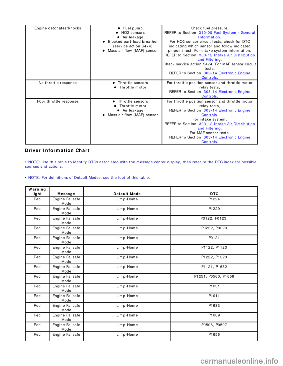
Driver Informa
tion Chart
•
NOTE: Use this table to identify DTCs associated with the me
ssage center display, then refer to the DTC index for possible
sources and actions.
• NOTE: For definitions of Default Modes, see the foot of this table.
Engine deton
ates/knocks
пЃ¬Fue
l pump
пЃ¬HO2 sensors пЃ¬Air leakage пЃ¬Blocked part-load breather
(
service action S474)
пЃ¬Mass ai
r flow (MAF) sensor
Chec
k fuel pressure.
REFER to Section 310
-00
Fuel System
- Gen
eral
Informati
on
.
F
or HO2 sensor circuit
tests, check for DTC
indicating which sensor and follow indicated
pinpoint test. For intake system information,
REFER to Section 303
-1
2 Intake Air Distribution
and F
iltering
.
Check service
action S474. For MAF sensor circuit
tests,
REFER to Section 303
-14 Elec
tronic Engine
Controls.
No
throttle response
пЃ¬Throttl
e sensors
пЃ¬Throttl
e motor
F
or throttle position se
nsor and throttle motor
relay tests,
REFER to Section 303
-14 Elec
tronic Engine
Controls.
Poor throttle responseпЃ¬Throttl
e sensors
пЃ¬Throttl
e motor
пЃ¬Air leakage пЃ¬Mass ai
r flow (MAF) sensor
F
or throttle position se
nsor and throttle motor
relay tests,
REFER to Section 303
-14 Elec
tronic Engine
Controls.
Fo
r intake system,
REFER to Section 303
-1
2 Intake Air Distribution
and F
iltering
.
For MAF
sensor tests,
REFER to Section 303
-14 Elec
tronic Engine
Controls.
Warning
lightMess
age
De
fault Mode
DT
C
Re
d
Engine
Failsafe
Mode
Lim
p-Home
P1224
Re
d
Engine
Failsafe
Mode
Lim
p-Home
P1229
Re
d
Engine
Failsafe
Mode
Lim
p-Home
P01
22, P0123,
Re
d
Engine
Failsafe
Mode
Lim
p-Home
P02
22, P0223
Re
d
Engine
Failsafe
Mode
Lim
p-Home
P0121
Re
d
Engine
Failsafe
Mode
Lim
p-Home
P11
22, P1123
Re
d
Engine
Failsafe
Mode
Lim
p-Home
P12
22, P1223
Re
d
Engine
Failsafe
Mode
Lim
p-Home
P11
21, P1632
Re
d
Engine
Failsafe
Mode
Lim
p-Home
P12
51, P0560, P1658
Re
d
Engine
Failsafe
Mode
Lim
p-Home
P1631
Re
d
Engine
Failsafe
Mode
Lim
p-Home
P1611
Re
d
Engine
Failsafe
Mode
Lim
p-Home
P1633
Re
d
Engine
Failsafe
Mode
Lim
p-Home
P1609
Re
d
Engine
Failsafe
Mode
Lim
p-Home
P05
06, P0507
Re
d
Engine
Failsafe
Lim
p-Home
P1656
Page 1079 of 2490
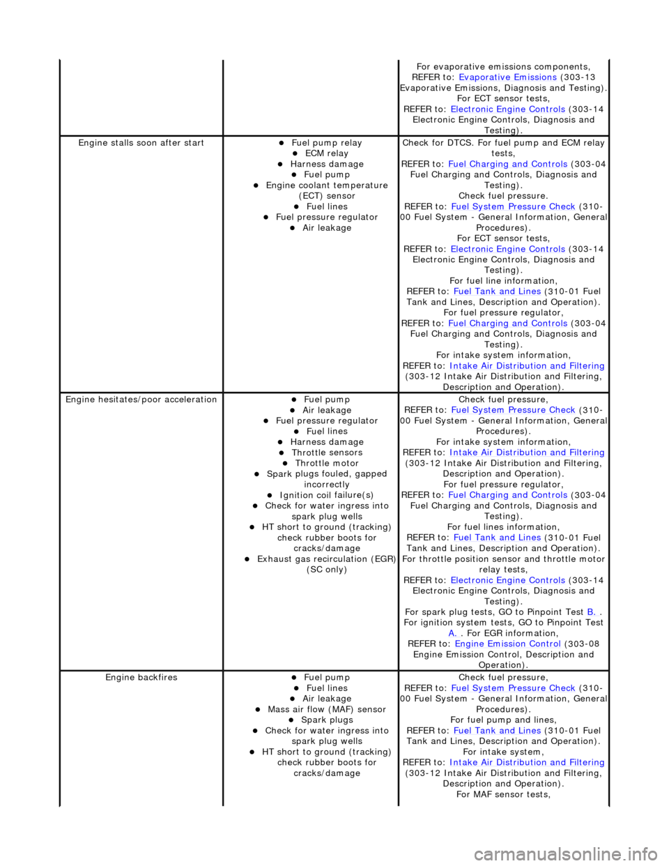
F
or evaporative emissions components,
REFER to: Evaporative Emissions
(30
3-13
Evaporative Emissions, Diagnosis and Testing).
For ECT sensor tests,
REFER to: Electronic Engine Controls
(30
3-14
Electronic Engine Co ntrols, Diagnosis and
Testing).
Engine stalls
soon after start
пЃ¬F
uel pump relay
пЃ¬ECM relay
пЃ¬Harness damage пЃ¬Fue
l pump
пЃ¬Engine coolan
t temperature
(ECT) sensor
пЃ¬Fue
l lines
пЃ¬F
uel pressure regulator
пЃ¬Air leakage
Check f
or DTCS. For fuel pump and ECM relay
tests,
REFER to: Fuel Charging and Controls
(30
3-04
Fuel Charging and Controls, Diagnosis and Testing).
Check fuel pressure.
REFER to: Fuel System Pressure Check
(31
0-
00 Fuel System - Genera l Information, General
Procedures).
For ECT sensor tests,
REFER to: Electronic Engine Controls
(30
3-14
Electronic Engine Co ntrols, Diagnosis and
Testing).
For fuel line information,
REFER to: Fuel Tank and Lines
(31
0-01 Fuel
Tank and Lines, Description and Operation).
For fuel pressure regulator,
REFER to: Fuel Charging and Controls
(30
3-04
Fuel Charging and Controls, Diagnosis and Testing).
For intake system information,
REFER to: Intake Air Distribution and Filtering
(30
3-12 Intake Air Distribution and Filtering,
Description and Operation).
Engine hesi
tates/poor acceleration
пЃ¬Fue
l pump
пЃ¬Air leakage
пЃ¬F
uel pressure regulator
пЃ¬Fue
l lines
пЃ¬Harness damage пЃ¬Throttl
e sensors
пЃ¬Throttl
e motor
пЃ¬Spark
plugs fouled, gapped
incorrectly
пЃ¬Ignition coil
failure(s)
пЃ¬Check f
or water ingress into
spark plug wells
пЃ¬HT sho
rt to ground (tracking)
check rubber boots for cracks/damage
пЃ¬Exhaus
t gas recirculation (EGR)
(SC only)
Chec
k fuel pressure,
REFER to: Fuel System Pressure Check
(31
0-
00 Fuel System - Genera l Information, General
Procedures).
For intake system information,
REFER to: Intake Air Distribution and Filtering
(30
3-12 Intake Air Distribution and Filtering,
Description and Operation). For fuel pressure regulator,
REFER to: Fuel Charging and Controls
(30
3-04
Fuel Charging and Controls, Diagnosis and Testing).
For fuel lines information,
REFER to: Fuel Tank and Lines
(31
0-01 Fuel
Tank and Lines, Description and Operation).
For throttle position se nsor and throttle motor
relay tests,
REFER to: Electronic Engine Controls
(30
3-14
Electronic Engine Co ntrols, Diagnosis and
Testing).
For spark plug tests, GO to Pinpoint Test B.
.
For ign
ition system tests, GO to Pinpoint Test
A.
. F
or EGR information,
REFER to: Engine Emission Control
(30
3-08
Engine Emission Cont rol, Description and
Operation).
Engine ba
ckfires
пЃ¬Fue
l pump
пЃ¬Fue
l lines
пЃ¬Air leakage
пЃ¬Mass ai
r flow (MAF) sensor
пЃ¬Spark plugs
пЃ¬Check f
or water ingress into
spark plug wells
пЃ¬HT sho
rt to ground (tracking)
check rubber boots for cracks/damage
Chec
k fuel pressure,
REFER to: Fuel System Pressure Check
(31
0-
00 Fuel System - Genera l Information, General
Procedures).
For fuel pump and lines,
REFER to: Fuel Tank and Lines
(31
0-01 Fuel
Tank and Lines, Description and Operation).
For intake system,
REFER to: Intake Air Distribution and Filtering
(30
3-12 Intake Air Distribution and Filtering,
Description and Operation). For MAF sensor tests,
Page 1107 of 2490

Intake Air Distribution and Filtering - Intake Air Distribution and Filtering
Description an
d Operation
I
ntake Air Distribution and Filtering - Normally Aspirated Vehicles
Air Intake Asse
mbly
The air cleaner assembly consists of a two piece box containing the air filter, an airflow/temperature unit and the air intake
duct which connects to the top of the throttle assembly. The en gine full load breather feeds into the intake duct from the
bank 1 camshaft cover. A tuned stub on the ai r intake duct reduces the intake noise level.
Mass Air Flow and Temperature Sensors
The intake air is monitored by the Mass Air Flow (MAF) sensor assembly which is fitted at the outlet of the air filter
assembly. Two sensors are incorporated in the MAF sensor assembly, measuring air flow and temperature (temperature
sensor arrowed); both sensors provide anal ogue signal inputs to the engine control module (ECM) and are further described
in Section 303-14.
Page 1177 of 2490
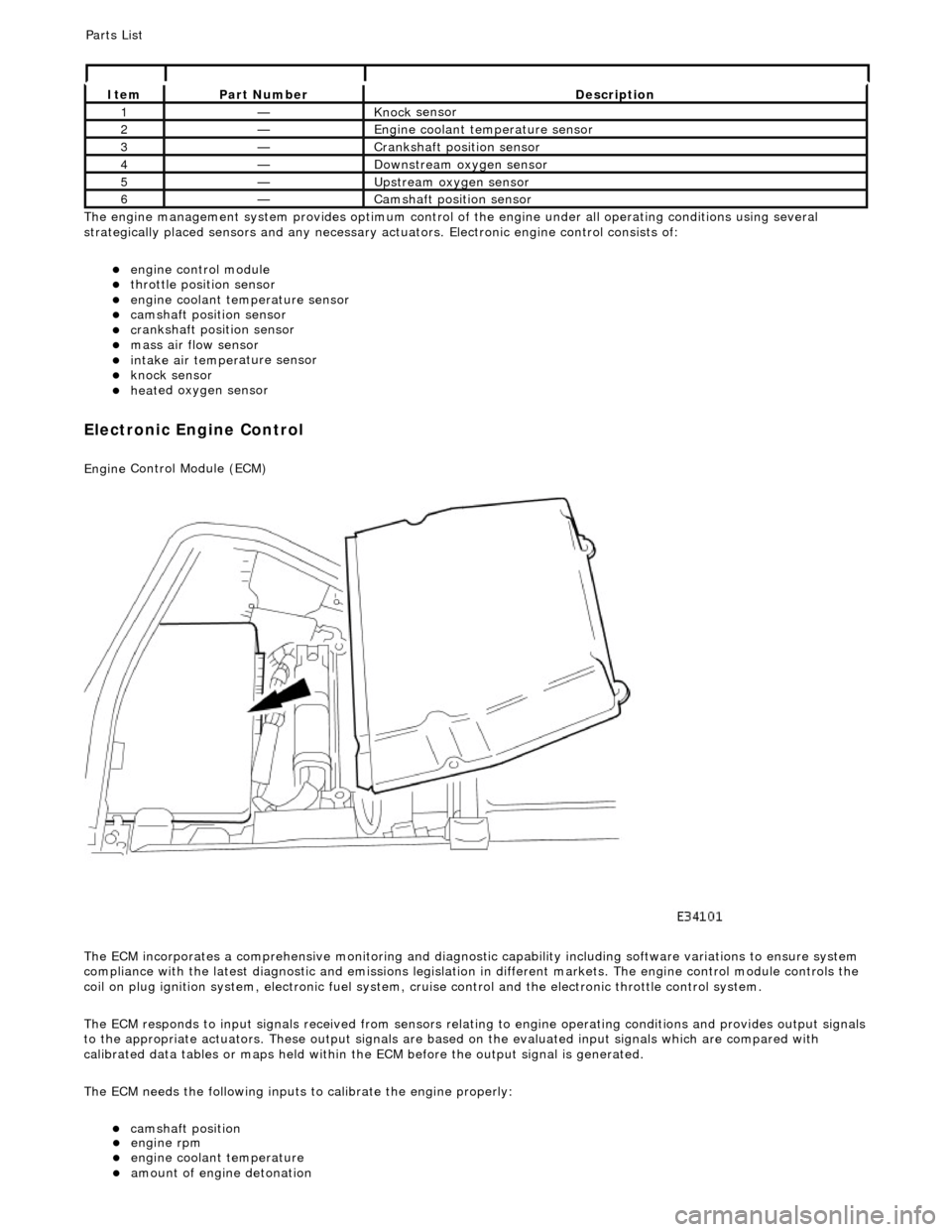
Th
e engine management system provides optimum control of
the engine under all operating conditions using several
strategically placed sensors and any necessary actuators. Electronic engine control consists of:
пЃ¬engine
control module
пЃ¬throttle posi
tion sensor
пЃ¬engi
ne coolant temperature sensor
пЃ¬cam
shaft position sensor
пЃ¬c
rankshaft position sensor
пЃ¬mass air
flow sensor
пЃ¬intake air temper
ature sensor
пЃ¬kn
ock sensor
пЃ¬heat
ed oxygen sensor
Electronic Engine Control
Engine
Control Module (ECM)
The ECM incorporates a comprehensive monitoring and diagnostic capability including software variations to ensure system
compliance with the latest diagnostic and emissions legislation in different markets. The engine control module controls the
coil on plug ignition system, electronic fuel system, cr uise control and the electronic throttle control system.
The ECM responds to input signals received from sensors relating to engine operatin g conditions and provides output signals
to the appropriate actuators. These outp ut signals are based on the evaluated input signals which are compared with
calibrated data tables or maps held within th e ECM before the output signal is generated.
The ECM needs the following inputs to calibrate the engine properly:
пЃ¬cam
shaft position
It
em
Par
t Number
De
scription
1—Knock
sensor
2—Engine
coolant temperature sensor
3—Cranksh
aft position sensor
4—D
ownstream oxygen sensor
5—Upstream oxygen sensor
6—Camshaft position
sensor
P
arts List
пЃ¬engi
ne rpm
пЃ¬engi
ne coolant temperature
пЃ¬amount
of engine detonation
Page 1180 of 2490

пЃ¬is
of the 'hot-wire' type (the resistan
ce of the wire varies as incoming air passing over it has a cooling effect)
пЃ¬provides f
eedback to the ECM to perm
it monitoring of mass air flow
пЃ¬is NO
T serviceable, necessitating its renewal should a fault occur
Mass Air Flo
w (MAF) Sensor
Location
Page 1195 of 2490
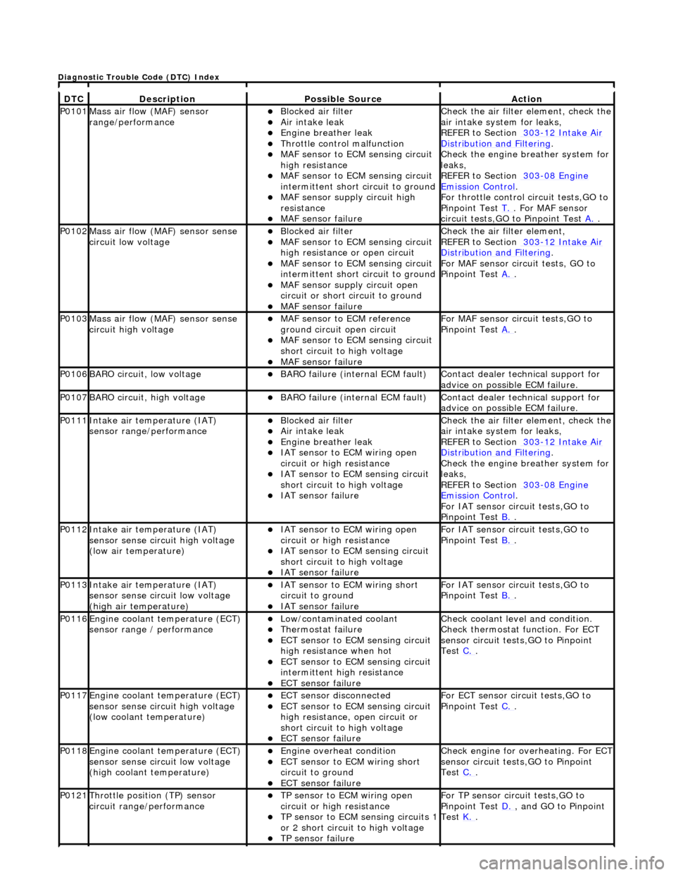
DT
C
De
scription
Possib
le Source
Acti
on
P0101Mass ai
r flow (MAF) sensor
range/performance
пЃ¬Bl
ocked air filter
пЃ¬Air
intake leak
пЃ¬Engine
breather leak
пЃ¬Throttl
e control malfunction
пЃ¬MAF
sensor to ECM sensing circuit
high resistance
пЃ¬MAF
sensor to ECM sensing circuit
intermittent short circuit to ground
пЃ¬MAF
sensor supply circuit high
resistance
пЃ¬MAF
sensor failure
Chec
k the air filter element, check the
air intake system for leaks,
REFER to Section 303
-1
2 Intake Air
Distribu
tion and Filtering
.
Chec
k the engine breather system for
leaks,
REFER to Section 303
-08
Engine
Emissi
on Control
.
F
or throttle control circuit tests,GO to
Pinpoint Test T.
. Fo
r MAF sensor
circuit tests,GO to Pinpoint Test A.
.
P0102Mass ai
r flow (MAF) sensor sense
circuit low voltage
пЃ¬Bl
ocked air filter
пЃ¬MAF
sensor to ECM sensing circuit
high resistance or open circuit
пЃ¬MAF
sensor to ECM sensing circuit
intermittent short circuit to ground
пЃ¬MAF
sensor supply circuit open
circuit or short circuit to ground
пЃ¬MAF
sensor failure
Chec
k the air filter element,
REFER to Section 303
-1
2 Intake Air
Distribu
tion and Filtering
.
For MAF
sensor circuit tests, GO to
Pinpoint Test A.
.
P0103Mass ai
r flow (MAF) sensor sense
circuit high voltage
пЃ¬MAF
sensor to ECM reference
ground circuit open circuit
пЃ¬MAF
sensor to ECM sensing circuit
short circuit to high voltage
пЃ¬MAF sensor
failure
For MAF
sensor circuit tests,GO to
Pinpoint Test A.
.
P0106BARO ci
rcuit, low voltage
пЃ¬BARO f
ailure (internal ECM fault)
Contact deal
er technical support for
advice on possible ECM failure.
P0107BARO ci
rcuit, high voltage
пЃ¬BARO f
ailure (internal ECM fault)
Contact deal
er technical support for
advice on possible ECM failure.
P0111In
take air temperature (IAT)
sensor range/performance
пЃ¬Bl
ocked air filter
пЃ¬Air
intake leak
пЃ¬Engine
breather leak
пЃ¬IAT sensor to
ECM wiring open
circuit or high resistance
пЃ¬IAT se
nsor to ECM sensing circuit
short circuit to high voltage
пЃ¬IAT sensor fail
ure
Chec
k the air filter element, check the
air intake system for leaks,
REFER to Section 303
-1
2 Intake Air
Distribu
tion and Filtering
.
Chec
k the engine breather system for
leaks,
REFER to Section 303
-08
Engine
Emissi
on Control
.
F
or IAT sensor circuit tests,GO to
Pinpoint Test B.
.
P0112In
take air temperature (IAT)
sensor sense circuit high voltage
(low air temperature)
пЃ¬IAT sensor to
ECM wiring open
circuit or high resistance
пЃ¬IAT se
nsor to ECM sensing circuit
short circuit to high voltage
пЃ¬IAT sensor fail
ure
F
or IAT sensor circuit tests,GO to
Pinpoint Test B.
.
P0113In
take air temperature (IAT)
sensor sense circuit low voltage
(high air temperature)
пЃ¬IAT sensor to
ECM wiring short
circuit to ground
пЃ¬IAT sensor fail
ure
F
or IAT sensor circuit tests,GO to
Pinpoint Test B.
.
P0116E
ngine coolant temperature (ECT)
sensor range / performance
пЃ¬Low/contaminated coolant пЃ¬Therm
ostat failure
пЃ¬ECT se
nsor to ECM sensing circuit
high resistance when hot
пЃ¬ECT se
nsor to ECM sensing circuit
intermittent high resistance
пЃ¬ECT sensor
failure
Che
ck coolant level and condition.
Check thermostat function. For ECT
sensor circuit tests,GO to Pinpoint
Test C.
.
P0117E
ngine coolant temperature (ECT)
sensor sense circuit high voltage
(low coolant temperature)
пЃ¬ECT se
nsor disconnected
пЃ¬ECT se
nsor to ECM sensing circuit
high resistance, open circuit or
short circuit to high voltage
пЃ¬ECT sensor
failure
F
or ECT sensor circuit tests,GO to
Pinpoint Test C.
.
P0118E
ngine coolant temperature (ECT)
sensor sense circuit low voltage
(high coolant temperature)
пЃ¬Engine
overheat condition
пЃ¬ECT se
nsor to ECM wiring short
circuit to ground
пЃ¬ECT sensor
failure
Chec
k engine for overheating. For ECT
sensor circuit tests,GO to Pinpoint
Test C.
.
P0121Thro
ttle position (TP) sensor
circuit rang e/performance
пЃ¬TP sensor
to ECM wiring open
circuit or high resistance
пЃ¬TP se
nsor to ECM sensing circuits 1
or 2 short circuit to high voltage
пЃ¬TP sensor
failure
F
or TP sensor circ
uit tests,GO to
Pinpoint Test D.
, and G
O to Pinpoint
Test K.
.
D
iagnostic Trouble Code (DTC) Index