P1646 JAGUAR X308 1998 2.G Workshop Manual
[x] Cancel search | Manufacturer: JAGUAR, Model Year: 1998, Model line: X308, Model: JAGUAR X308 1998 2.GPages: 2490, PDF Size: 69.81 MB
Page 1028 of 2490
Pinpoint Tests
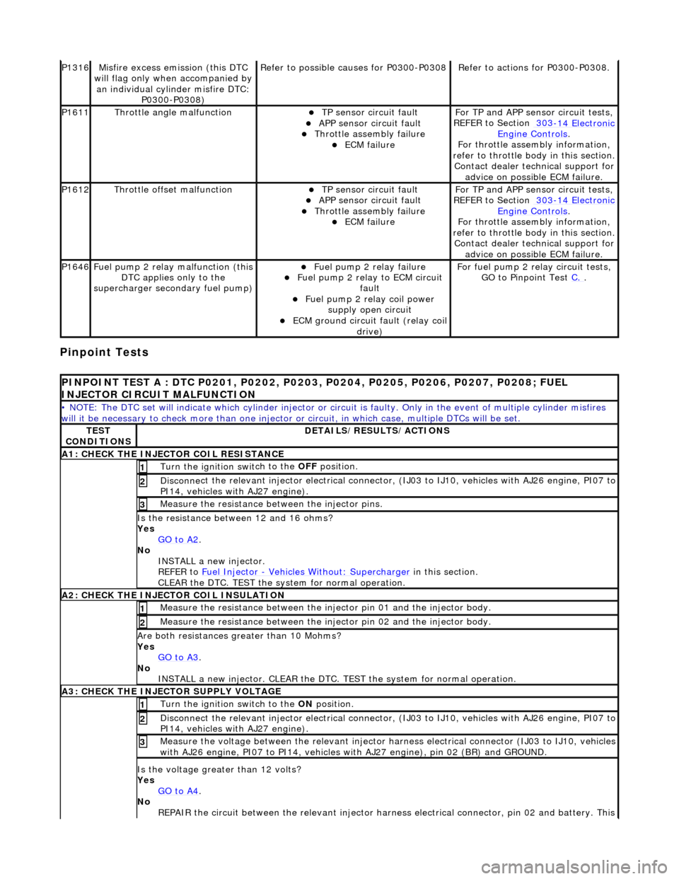
P1316Mi
sfire excess emission (this DTC
will flag only when accompanied by an individual cylinder misfire DTC: P0300-P0308)
Re
fer to possible causes for P0300-P0308
R
e
fer to actions for P0300-P0308.
P1611Thr
o
ttle angle malfunction
TP sensor
ci
rcuit fault
APP sensor circuit faul
t Throttle
assembly failure
ECM failu
r
e
F
or TP and APP
sens
or circuit tests,
REFER to Section 303
-14 El
ectronic
Engine
C
ontrols
.
F o
r throttle assembly information,
refer to throttle body in this section.
Contact dealer technical support for advice on possible ECM failure.
P1612Throttl e
offset malfunction
TP sensor
ci
rcuit fault
APP sensor circuit faul
t Throttle
assembly failure
ECM failu
r
e
F
or TP and APP
sens
or circuit tests,
REFER to Section 303
-14 El
ectronic
Engine
C
ontrols
.
F o
r throttle assembly information,
refer to throttle body in this section.
Contact dealer technical support for advice on possible ECM failure.
P1646Fu
el pump 2 relay malfunction (this
DTC applies only to the
supercharger secondary fuel pump)
Fu
el pump 2 relay failure
Fu
el pump 2 relay to ECM circuit
fault
Fu
el pump 2 relay coil power
supply open circuit
ECM ground circuit faul t (relay coil
drive)
For fuel pump 2 r
elay circuit tests,
GO to Pinpoint Test C.
.
PI
NPOINT TEST A : DTC P0201, P0202, P0203, P0204, P0205, P0206, P0207, P0208; FUEL
INJECTOR CIRCUIT MALFUNCTION
• NOTE
: The DTC set will indicate which cylinder injector or circ
uit is faulty. Only in the event of multiple cylinder misfires
will it be necessary to chec k more than one injector or circuit, in which case, multiple DTCs will be set.
TES
T
CONDITIONS
D E
TAILS/RESULTS/ACTIONS
A1
: CH
ECK THE INJECTOR COIL RESISTANCE
Turn the ignition swi
t
ch to the OFF
position.
1
Disconne
ct the relevant injector electrical connector
, (IJ03 to IJ10, vehicles with AJ26 engine, PI07 to
PI14, vehicles with AJ27 engine).
2
Meas ure t
he resistance between the injector pins.
3
Is
t
he resistance between 12 and 16 ohms?
Yes GO to A2
.
No
INST
ALL a new injector.
REFER to Fuel Injector
- Ve hicles With
out: Supercharger
in this
section.
CLEAR the DTC. TEST the system for normal operation.
A2: CHECK
THE INJECTOR COIL INSULATION
Meas
ure t
he resistance between the inje
ctor pin 01 and the injector body.
1
Measure t
he resistance between the inje
ctor pin 02 and the injector body.
2
Are both re
sistances greater than 10 Mohms?
Yes GO to A3
.
No
INST
ALL a new injector. CLEAR the DTC. TE
ST the system for normal operation.
A3: CHECK THE INJECTOR
SUPPLY VOLTAGE
Turn the ignition swi
t
ch to the ON
position.
1
Disconne
ct the relevant injector electrical connector
, (IJ03 to IJ10, vehicles with AJ26 engine, PI07 to
PI14, vehicles with AJ27 engine).
2
Meas ure t
he voltage between the relevant injector harness electrical connector (IJ03 to IJ10, vehicles
with AJ26 engine, PI07 to PI 14, vehicles with AJ27 engine), pin 02 (BR) and GROUND.
3
Is the volt
age greater than 12 volts?
Yes GO to A4
.
No
R
EPAIR the circuit between the relevant injector harn
ess electrical connector, pin 02 and battery. This
Page 1030 of 2490
Measure t
he resistance
between BT15 and GROUND.
2
Is the res
istance greater than 5 ohms?
Yes GO to B2
.
No
GO to B3
.
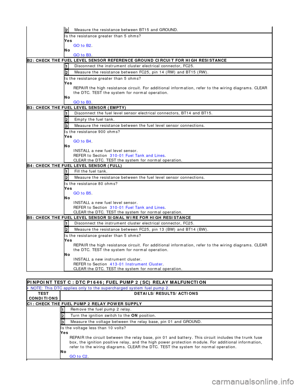
B2: CHECK THE FUEL
LEVEL SENSOR REFERE
NCE GROUND CIRCUIT FOR HIGH RESISTANCE
Disc
onnect the instrument cluster electrical connector, FC25.
1
Meas
ure t
he resistance between FC25, pin 14 (RW) and BT15 (RW).
2
Is the res
istance greater than 5 ohms?
Yes REPAIR the high resistance circui t. For additional information, refer to the wiring diagrams. CLEAR
the DTC. TEST the system for normal operation.
No GO to B3
.
B3: CHECK THE FUEL
LEVEL SENSOR (EMPTY)
Di
sc
onnect the fuel level sensor electrical connectors, BT14 and BT15.
1
Empty the fuel
tank. 2
Measure t
he resistance between the
fuel level sensor connections.
3
Is t
he resistance 900 ohms?
Yes GO to B4
.
No
INST
ALL a new fuel level sensor.
REFER to Section 310
-0 1
Fuel Tank and Lines
.
CLEAR t h
e DTC. TEST the system for normal operation.
B4:
CHECK
THE FUEL LEVEL SENSOR (FULL)
Fi
ll
the fuel tank.
1
Meas
ure t
he resistance between the
fuel level sensor connections.
2
Is
the resistance 80 ohms?
Yes GO to B5
.
No
INST
ALL a new fuel level sensor.
REFER to Section 310
-0 1
Fuel Tank and Lines
.
CLEAR t h
e DTC. TEST the system for normal operation.
B
5
: CHECK THE FUEL LEVEL SENSOR SIGNAL WIRE FOR HIGH RESISTANCE
Di
sc
onnect the instrument cluster electrical connector, FC25.
1
Meas
ure t
he resistance between FC25, pin 13 (BW) and BT14 (BW).
2
Is th
e res
istance greater than 5 ohms?
Yes REPAIR the high resistance circui t. For additional information, refer to the wiring diagrams. CLEAR
the DTC. TEST the system for normal operation.
No INSTALL a new instrument cluster.
REFER to Section 413
-01
Instrume
nt Cluster
.
CLEAR t h
e DTC. TEST the system for normal operation.
P
INPOINT TEST C : DTC P1646; FU
EL PUMP 2 (SC) RELAY MALFUNCTION
•
NO
TE: This DTC applies only to the
supercharged system fuel pump 2.
TES
T
CONDITIONS
D E
TAILS/RESULTS/ACTIONS
C
1
: CHECK THE FUEL PUMP 2 RELAY POWER SUPPLY
R
e
move the fuel pump 2 relay.
1
Turn the ignition swi
t
ch to the
ON position.
2
Meas
ure t
he voltage between the
relay base, pin 01 and GROUND.
3
Is the volt
age less than 10 volts?
Yes REPAIR the circuit between the rela y base, pin 01 and battery. This circuit includes the trunk fuse
box, the ignition positive relay, and the high power protection module. For additional information,
refer to the wiring diagrams. CLEAR the DTC. TEST the system for normal operation.
No GO to C2
.
Page 1207 of 2490
Pinpoint Tests
f
ailure
P1611Thr
ottle angle malfunction
TP sensor
circuit fault (refer to
P0121)
APP sensor circuit faul
t (refer to
P0121)
Throttl
e assembly failure
ECM failu
re
Se
e pinpoint tests for components
listed. For throttle body information,
REFER to Section 303
-04
Fuel
Charging and Con
trols
.
Contact deal
er technical support for
advice on possible ECM failure.
P1612Throttl
e offset malfunction
TP sensor
circuit fault (refer to
P0121)
APP sensor circuit faul
t (refer to
P0121)
Throttl
e assembly failure
ECM failu
re
Se
e pinpoint tests for components
listed. For throttle body information,
REFER to Section 303
-04
Fuel
Charging and Con
trols
.
Contact deal
er technical support for
advice on possible ECM failure.
P1637CAN AB
S/TCCM token missing
CAN
open circuit fault - ABS/TCCM
to ECM
CAN s
hort circuit fault
ABS/TCCM failu
re
ECM failu
re
F
or network circuit tests,
REFER to Section 418
-00
Module
Comm
unications Network
.
P1638CAN INST token missingCAN
open circuit fault - INST to
ECM
CAN s
hort circuit fault
INST
failure
ECM failu
re
F
or network circuit tests,
REFER to Section 418
-00
Module
Comm
unications Network
.
P1642CAN c
ircuit malfunction
CAN s
hort circuit fault
Control modul
e failure - check for
additional logged DTCs to locate
control module source
F
or network circuit tests,
REFER to Section 418
-00
Module
Comm
unications Network
.
P1643CAN TC
M token missing
CAN
open circuit fault - TCM to
ECM
CAN s
hort circuit fault
TCM failure
ECM failu
re
F
or network circuit tests,
REFER to Section 418
-00
Module
Comm
unications Network
.
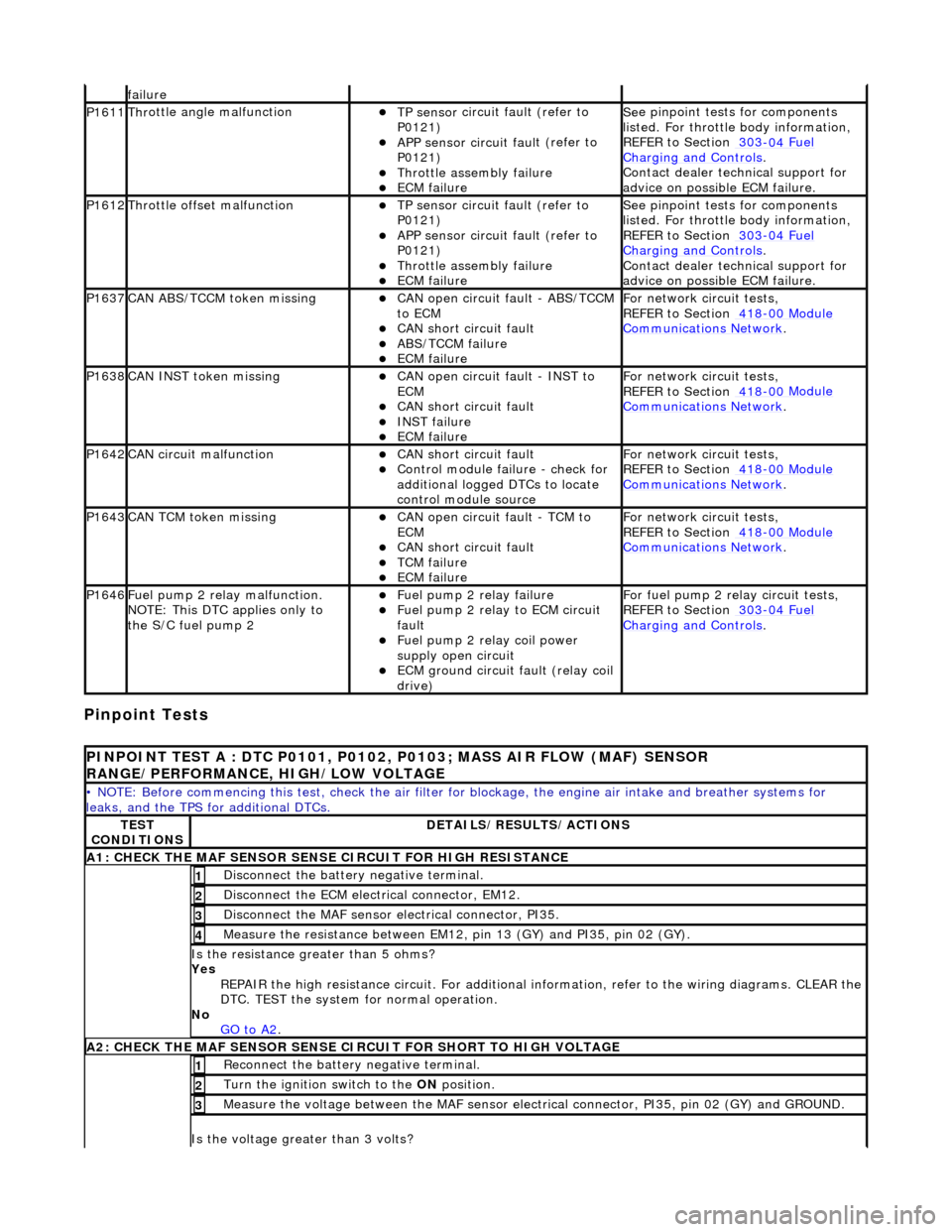
P1646F
uel pump 2 relay malfunction.
NOTE: This DTC applies only to
the S/C fuel pump 2
F
uel pump 2 relay failure
F
uel pump 2 relay to ECM circuit
fault
F
uel pump 2 relay coil power
supply open circuit
ECM ground circuit faul
t (relay coil
drive)
F
or fuel pump 2 relay circuit tests,
REFER to Section 303
-04
Fuel
Charging and Con
trols
.
P
INPOINT TEST A : DTC P0101, P0102, P0103; MASS AIR FLOW (MAF) SENSOR
RANGE/PERFORMANCE, HIGH/LOW VOLTAGE
•
NOTE: Before commencing this
test, check the air filter for blockage, the engine air inta ke and breather systems for
leaks, and the TPS for additional DTCs.
TE
ST
CONDITIONS
D
ETAILS/RESULTS/ACTIONS
A1: CHECK
THE MAF SENSOR SENS
E CIRCUIT FOR HIGH RESISTANCE
Di
sconnect the battery negative terminal.
1
D
isconnect the ECM electrical connector, EM12.
2
Di
sconnect the MAF sensor electrical connector, PI35.
3
Meas
ure the resistance between EM12, pin 13 (GY) and PI35, pin 02 (GY).
4
Is th
e resistance greater than 5 ohms?
Yes REPAIR the high resistance circuit. For additional information, refer to the wiring diagrams. CLEAR the
DTC. TEST the system for normal operation.
No GO to A2
.
A2: CHECK
THE MAF SENSOR SENSE CI
RCUIT FOR SHORT TO HIGH VOLTAGE
R
econnect the battery negative terminal.
1
Turn the ignition swi
tch to the ON
position.
2
M
easure the voltage between the MAF sensor electrical connector, PI35, pin 02 (GY) and GROUND.
3
Is th
e voltage greater than 3 volts?
Page 1698 of 2490
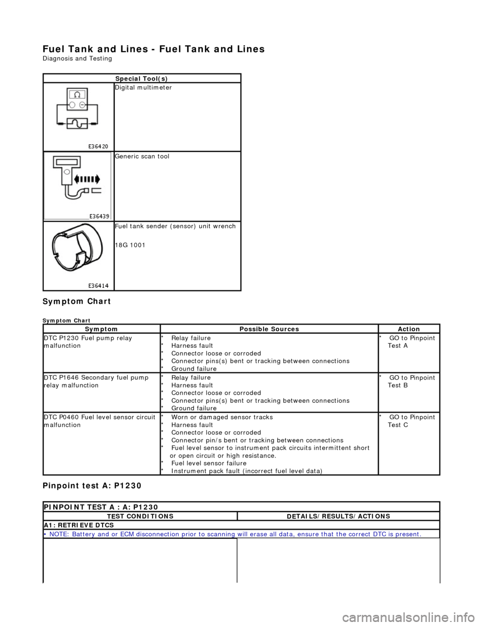
Fuel Tank and Lines - Fuel Tank and Li
nes
D
iagn
osis and Testing
Sym
p
tom Chart
Sy
m
ptom Chart
Pinpoint test A: P1230
S
p
ecial Tool(s)
D
i
gital multimeter
Generi
c scan tool
F
u
el tank sender (sensor) unit wrench
18G 1001
Sy m
ptom
Possib
l
e Sources
Acti
o
n
D
T
C P1230 Fuel pump relay
malfunction
Re lay
failure
Harness fault
Connector loose or corroded
Connector pins(s) bent or tracking between connections
Ground failure
*
*
*
*
*
GO to Pinpoint
Test A
*
D
T
C P1646 Secondary fuel pump
relay malfunction
Re lay
failure
Harness fault
Connector loose or corroded
Connector pins(s) bent or tracking between connections
Ground failure
*
*
*
*
*
GO to Pinpoint
Test B
*
D
T
C P0460 Fuel level sensor circuit
malfunction
Worn
or damaged sensor tracks
Harness fault
Connector loose or corroded
Connector pin/s bent or tracking between connections
Fuel level sensor to instrument pack circui ts intermittent short
or open circuit or high resistance. Fuel level sensor failure
Instrument pack fault (inc orrect fuel level data)
*
*
*
*
*
*
*
GO to Pinpoint
Test C
*
P
INPOINT TES
T A : A: P1230
T
E
ST CONDITIONS
D
E
TAILS/RESULTS/ACTIONS
A1
: RETRIEV
E DTCS
•
NOTE
: Battery and or ECM disconnection prior to scanning wi
ll erase all data, ensure that the correct DTC is present.
Page 1712 of 2490
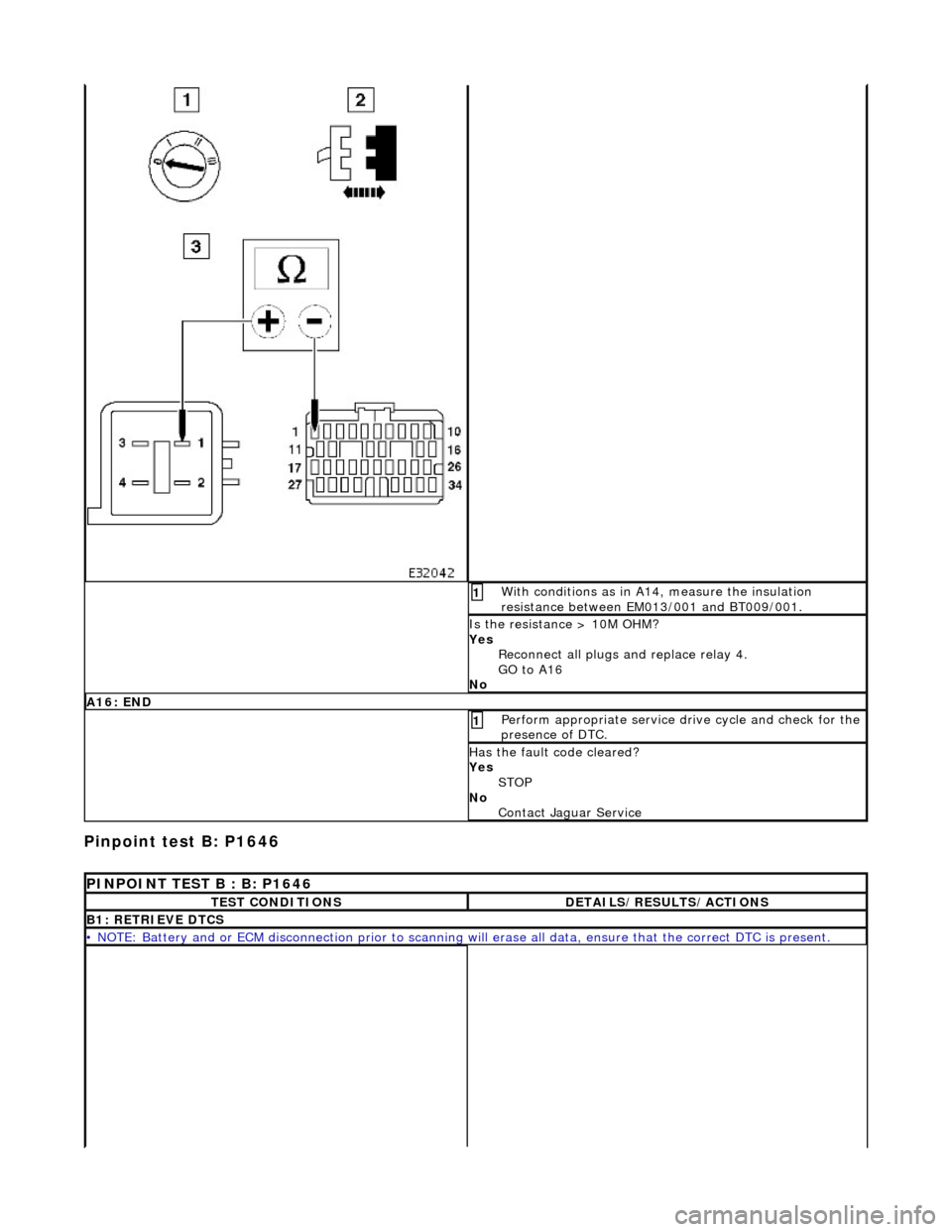
Pinpoint test B:
P1646
W
i
th conditions as in A14, measure the insulation
resistance between EM013/001 and BT009/001.
1
I s
the resistance > 10M OHM?
Yes Reconnect all plugs and replace relay 4.
GO to A16
No
A 16:
END
Perform
a
ppropriate service drive cycle and check for the
presence of DTC.
1
Has th
e fault code cleared?
Yes STOP
No Contact Ja
guar Serv ice
PINPOINT TEST B : B: P1646
TE
ST CONDITIONS
D
E
TAILS/RESULTS/ACTIONS
B1
: RETRI
EVE DTCS
•
NOTE
: Battery and or ECM disconnection prior to scanning wi
ll erase all data, ensure that the correct DTC is present.