air conditioning JAGUAR X308 1998 2.G Workshop Manual
[x] Cancel search | Manufacturer: JAGUAR, Model Year: 1998, Model line: X308, Model: JAGUAR X308 1998 2.GPages: 2490, PDF Size: 69.81 MB
Page 20 of 2490

В В В В В В В В В В В В 310‐01: В Fu elВ Tank В and В Lines В
В В В В В В В В В В В В В В В В RemovalВ and В Installation В
В В В В В В В В В В В В В В В В В В В В FuelВ Level В Sensor В (88.25.32) В
В В В В В В В В В В В В В В В В В В В В FuelВ Pump В (19.45.08) В
В В В В В В В В В В В В В В В В В В В В FuelВ Tank В (19.55.01) В
В
            310‐02
:
В Acceleration В Control В
В В В В В В В В В В В В В В В В GeneralВ Procedures В
В В В В В В В В В В В В В В В В В В В В Accelerator В CableВ Adjustment В (12.20.05) В
В В В В В В В В В В В В В В В В RemovalВ and В Installation В
В В В В В В В В В В В В В В В В В В В В Accelerator В CableВ (19.20.06) В
В
В В В В В В В В В В В В 310‐03: В Speed В Control В
В В В В В В В В В В В В В В В В Diagnosis В and В Testing В
В В В В В В В В В В В В В В В В В В В В SpeedВ Con
trolВ
В
В В В В 4: В Electrical В
В
В В В В В В В В 412: В Climate В Control В System В
В
В В В В В В В В В В В В 412‐00: В Climate В Control В System  ‐ General В InformationВ
В В В В В В В В В В В В В В В В Specification В
В В В В В В В В В В В В В В В В Description В and В Operation В
В В В В В В В В В В В В В В В В В В В В ClimateВ ControlВ System В
В В В В В В В В В В В В В В В В Diagnosis В and В Testing В
В В В В В В В В В В В В В В В В В В В В ClimateВ ControlВ System В
В В В В В В В В В В В В В В В В GeneralВ Procedures В
В В В В В В В В В В В В В В В В В В В В AirВ Conditioning В (A/C) В System В Check ‐ RetailВ Procedure В
В В В В В В В В В В В В В В В В В В В В AirВ Conditioning В (A/C) В System В Recovery, В Evacuation В and В ChargingВ (82.30.30) В
В В В В В В В В В В В В В В В В В В В В Contaminated В Refrigerant В Ha
ndling В
В В В В В В В В В В В В В В В В В В В В ManifoldВ GaugeВ SetВ Connection В
В В В В В В В В В В В В В В В В В В В В RefrigerantВ AddingВ (82.30.02) В
В В В В В В В В В В В В В В В В В В В В RefrigerantВ OilВ Adding В
В В В В В В В В В В В В В В В В В В В В RefrigerantВ SystemВ Tests В
В
В В В В В В В В В В В В 412‐01: В Air В Distribution В and В Filtering В
В В В В В В В В В В В В В В В В Description В and В Operation В
Page 21 of 2490

В В В В В В В В В В В В В В В В В В В В AirВ Distributio nВ and В Filt
ering
В
В В В В В В В В В В В В В В В В Diagnosis В and В Testing В
В В В В В В В В В В В В В В В В В В В В AirВ Distribution В and В Filtering В
В В В В В В В В В В В В В В В В RemovalВ and В Installation В
В В В В В В В В В В В В В В В В В В В В CenterВ Registers В (82.20.38) В
В В В В В В В В В В В В В В В В В В В В DriverВ Side В Blower В Motor В (82.25.56) В
В В В В В В В В В В В В В В В В В В В В PassengerВ Side В Blower В Motor В (82.25.55) В
В В В В В В В В В В В В В В В В В В В В PlenumВ Chamber В (82.20.87) В
В
В В В В В В В В В В В В 412‐02: В Heating В and В Ventilation В
В В В В В В В В В В В В В В В В Description В and В Operation В
В В В В В В В В В В В В В В В В В В В В HeatingВ and В Ventilation В
В В В В В В В В В В В В В В В В В В В
В В В В В В В В В В В В В В В В В В В В В
В В
В В В В В В В В В В В В В В В В Removal
В and В Installation В
В В В В В В В В В В В В В В В В В В В В Heater
В Core В (80.20.29) В
В В В В В В В В В В В В В В В В В В В В Heater
В Core В and В Evaporator В Core В Housing В (82.25.21) В
В
В В В В В В В В В В В В 412
‐03: В Air В Conditioning В
В В В В В В В В В В В В В В В В Description
В and В Operation В
В В В В В В В В В В В В В В В В В В В В AirВ
Conditioning В
В В В В В В В В В В В В В В В В Diagnosis
В and В Testing В
В В В В В В В В В В В В В В В В В В В В AirВ
Conditioning В
В В В В В В В В В В В В В В В В Removal
В and В Installation В
В В В В В В В В В В В В В В В В В В В В AirВ
Conditioning В (A/C) В CompressorВ (82.10.20)В
В В В В В В В В В В В В В В В В В В В В Condenser
В Core В (82.15.07) В
В В В В В В В В В В В В В В В В В В В В Evaporator
В Core В (82.25.20) В
В В В В В В В В В В В В В В В В В В В В Press
ureВ Cutoff В Switch В (82.10.32) В
В В В В В В В В В В В В В В В В В В В В Receiver
В Drier В (82.17.01) В
В
В В В В В В В В В В В В 412
‐04: В Control В Components В
В В В В В В В В В В В В В В В В Description
В and В Operation В
В В В В В В В В В В В В В В В В В В В В ControlВ
Components В
В В В В В В В В В В В В В В В В Diagnosis
В and В Testing В
В В В В В В В В В В В В В В В В В В В В ControlВ
Components В
В В В В В В В В В В В В В В В В Removal
В and В Installation В
В В В В В В В В В В В В В В В В В В В В AirВ
Discharge В Temperature В Sensor В (82.20.64) В
Page 35 of 2490
General Infor
mation - Gene
ral Service Information
Description an
d Operation
Safety Notice
Appropri
ate service me
thods and proper repair procedures are essential for the safe, reliable operation of all motor vehicles,
as well as the safety of the person do ing the work. This manual provides genera l directions for accomplishing service and
repair work with tested, effect ive, techniques. Following them will help assure reliability.
There are numerous variations in procedures, techniques, tools, and parts for servicing vehicles, as well as in the skill of the
person doing the work. This manual cannot possibly anticipate all such variations and provide advice or cautions as to each.
Accordingly, anyone who depart s from the instructions provided in the manua l must first establish that neither personal
safety nor vehicle integrity is compromised from choices of methods, tools or parts.
Notes, Ca
utions and Warnings
Throughout
this manual, important inform
ation is highlighted by the use of notes, cautions and warnings. NOTES give
additional information on a topic or proc edure, CAUTIONS are given to prevent da mage to the vehicle, and WARNINGS are
given to prevent personal injury.
Worksh
op Manual Organization
This
manual incorporates descript
ive, diagnostic, and repair information to help trained Jaguar technicians complete service
and rectification procedures. The informat ion can be accessed by choosing the appropriate five digit section number. For
example, Section 412-03 covers air conditioning , which is part of the Climate Control System.
The manual is organized into groups covering generic aspects of the vehicle systems; the first digit of the section
number represents a group se lected from the following:
1. General Information.
2. Chassis.
3. Powertrain.
4. Electrical.
5. Body and Paint.
Each of the groups comprises sections re lating to specific areas of the vehicle.
The second and third digits of the section number indicate the vehicle system.
The last two digits of the se ction number define the system covered, more specifically.
Each section comprises one or more of the following sub-sections:
Specification
Page 39 of 2490
Before inspecting a component for wear or per
forming a dimensional check,
ensure that it is absolutely clean; a slight smear
of grease can conceal an incipient failure. When a component is to be checked dimensionally against figures quoted for it,
use the correct equipment (surface plates, micrometers, dial gauges etc.) in serviceable condition. The use of makeshift
equipment can be dangerous. Reject a component if its dimensio ns are outside the limits quoted, or if damage is apparent.
A part may be refitted if its critical di mension is exactly to the limit size and it is otherwise satisfactory. Use Plastigauge 12
Type PG-1 for checking bearing surface clearance, e.g. big end bearing shell to crank jour nal. Instructions for the use of
Plastigauge and a scale giving bearing clearances in steps of 0.0025 mm (0.0001 in) are supplied with the package.
Safety
Precautions
• WAR
NINGS:
WORKING ON THE FUEL SYSTEM RESULTS IN FUEL AND FUEL VAPOUR BEING PRESENT IN THE ATMOSPHERE. FUEL
VAPOUR IS EXTREMELY FLAMMABLE, HENCE GREAT CARE MUST BE TAKEN WHILST WORKING ON THE FUEL SYSTEM.
ADHERE STRICTLY TO THE FOLLOWING PRECAUTIONS:
пЃ¬DO
NOT SMOKE IN THE WORK AREA.
пЃ¬DISP
LAY 'NO SMOKING' SIGNS AROUND THE AREA.
пЃ¬DISCONNECT TH
E BATTERY BEFORE WORKING ON THE FUEL SYSTEM.
пЃ¬DO NOT CONNEC
T/DISCONNECT ELECTRICAL CIRCUITS
, USE ELECTRICAL EQUIPMENT OR OTHER TOOLS OR
ENGAGE IN WORKING PRACTICES WHICH IN ANY WAY MAY RESULT IN THE PRODUCTION OF SPARKS.
пЃ¬ENS
URE THAT A CO2 FIRE EXTINGUISHER IS CLOSE AT HAND.
пЃ¬ENS
URE THAT DRY SAND IS AVAILABLE TO SOAK UP ANY FUEL SPILLAGE.
пЃ¬EMP
TY FUEL USING SUITABLE FIRE PROOF EQUIPMENT IN
TO AN AUTHORIZED EXPLOSION PROOF CONTAINER.
пЃ¬DO NOT EMP
TY FUEL WHILE WORKING IN A WORKSHOP OR A PIT.
пЃ¬ENS
URE THAT WORKING AREA IS WELL VENTILATED.
пЃ¬ENS
URE THAT ANY WORK ON THE FUEL SYSTEM IS ON
LY CARRIED OUT BY EXPERIENCED AND WELL QUALIFIED
MAINTENANCE PERSONNEL.
пЃ¬ENS
URE THAT FUME EXTRACTION EQUIPMENT IS USED WHERE APPROPRIATE.
FUME EXTRACTION EQUIPMENT MUST BE IN OPERATION WHEN SOLVENTS ARE USED E.G. TRICHLOROETHANE,
WHITE SPIRIT, SBP3, METHYLENE CHLORIDE, PERCHLORETHY LENE. DO NOT SMOKE IN THE VICINITY OF VOLATILE
DEGREASING AGENTS.
General workshop practices:
пЃ¬Disc
onnect the grounded termin
al of the vehicle battery.
пЃ¬D
o not apply heat in an attempt to free seized nuts or fitt
ings; as well as causing damage to protective coatings,
there is a risk of damage from stray heat to electronic equipment and brake lines.
пЃ¬Keep oils and solven
ts away from naked flames and other sour
ces of ignition.
пЃ¬Adhere str
ictly to handling and safety inst
ructions given on containers and labels.
пЃ¬E
nsure that a suitab
le form of fire extinguisher is conveniently located.
пЃ¬Wh
en using electrical tools and equipment, inspect the power
lead for damage and check that it is properly earthed.
пЃ¬D
o not leave tools, equipment, spilt oil etc. around the work area.
Working beneath a vehicle:
пЃ¬Wh
enever possible, use a ramp or
pit in preference to jacking.
пЃ¬Posit
ion chocks at the wheels as we
ll as applying the parking brake.
пЃ¬N
ever rely on a jack alone to support a
vehicle; use axle stands, or blocks care fully placed at the jacking points, to
provide a rigid location.
пЃ¬Ch
eck that any lifting equipment used has adeq
uate capacity and is fully serviceable.
Working on air conditioning systems:
пЃ¬D
o not disconnect any pipes of the refrigeration system
unless you are trained and instructed to do so; a refrigerant
is used which can cause blindness if allowed to come into contact with the eyes.
Health Protection
P
rolonged and repeated contact with mineral oil will result in the removal of natural oils from the skin, leading to dryness,
In
spection
Page 42 of 2490
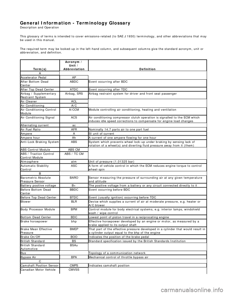
General Information - Terminology Glossary
Description an
d Operation
This glossary of terms is intended to cover emissions-related (to SAE J 1930) term inology, and other abbreviations that may
be used in this manual.
The required term may be looked-up in th e left-hand column, and subsequent columns give the standard acronym, unit or
abbreviation, and definition.
Te rm
(s)
Acr
ony
m /
Unit /
Abbreviation
De fi
nition
A
Accel
e
rator Pedal
AP
Af
ter Botto
m Dead
Center
ABDCEvent occurri ng after
BDC
Af
ter Top Dead CenterATDCEvent occurri ng after
TDC
Ai
rbag /
Supplementary
Restraint System
Airbag, SRSAi rbag restraint system for
dr
iver and front seat passenger
Air Cleane rACL
Air ConditioningA/C
Air Conditioning Con t
rol
Module
A/CCMModule c
ontrolling air conditioning, heating and ventilation
Air Conditioning SignalACSA
i
r conditioning compressor clutch operation is signalled to the ECM which
induces idle speed corrections to co mpensate for engine load changes
Alternating cu
rrent
ac
Ai
r Fuel R
atio
AFRN
omi
nally 14.7 parts air to one part fuel
Ampe
reASI unit of current
Ampere hourAhA current of one ampere
fl
owing for one hour
Anti-Lock Braking SystemABSS
y
stem which prevents wheel lock-up
under braking by sensing lack of
rotation of a wheel(s) and divertin g fluid pressure away from it (them)
ABS Control Mo
dule
ABS CM
ABS /
T
raction Control
Control Module
ABS / T
C CM
Atmosph
e
re
atmU
n
it of pressure (1.01325 bar)
Au
to
matic Stability
Control
ASCA form of vehicle
control
in which the ECM reduces en gine torque to control
wheel-spin
B
Baro me
tric Absolute
Pressure Sensor
BAR OSensor measuring the pressure of surr ou
nding air at any given temperature
and altitude
Bat t
ery positive voltage
B+The posi
ti
ve voltage from a battery or
any circuit connected directly to it
Before Bottom Dead
CenterBBDCEvent occurri ng before BD
C
Before Top Dead
Center
BTD
CEvent (usual ly
ignition) occurring before TDC
Blowe
rBLRDe
vice which supplies a current of air at
moderate pressure, e.g. heater or
A/C blower
Body Processor M
odule
BPMControl modu
le
for body electrical systems, e.g. interior lamps, windshield
wash / wipe control
Bott om D
ead Center
BD
CLowest poin t of piston
travel in a reciprocating engine
Brake hors
epowe
r
bhpEffecti
ve horsepower devel
oped by an
engine or motor, as measured by a
brake applied to its output shaft
Brake Mean Effective
Pres sureBME PThat p
art of the effective
pressure developed in a cyli nder that would result in
a cylinder output equal to the bhp of the engine
Brake On/ O
ff
BOOIn
dic
ates the position of the brake pedal
Br
it
ish Standard
BSStan
dar
d specification issued by the British Standards Institution
Br
it
ish Standard
Automotive
BSAu
BusTopology of a commu n
ication network
Bypass
AirBPAMechanica l
control of throttle bypass air
C
Camshaft Posit
i
on Sensor
CMPSIndi
cat
es camshaft position
Canadian Motor
V
ehicle
CMVSS
Page 522 of 2490
diverter val
ve (if fitted) and oil filter.
пЃ¬Main
bearings
which are grooved in the upper positions and plain in
the lower positions. They are manufactured from
aluminium / tin material.
пЃ¬A c
rankshaft with under
cuts and rolled fillets for extra strength.
пЃ¬Fracture
-split connecting rods in sintered-forged steel.
пЃ¬Brackets
bolted to the front of
the cylinder
block are used to mo unt all accessories.
пЃ¬A sin
gle, seven ribbed vee belt
drives the accessories.
пЃ¬An au
tomatic belt tensioner for the front accessory drive,
incorporating a wear indicator.
пЃ¬An advanced en
gine management system inco
rporating electronic throttle control.
пЃ¬The un
it meets the requirements of the CARB OBDII USA legislation.
Ancillary Systems
The an
ci
llary systems, driven by the engine, each have a
detailed Description and Operation along with Diagnostic
Procedures, and Removal and Installation instructions ; refer to the following sections of this manual:
пЃ¬Power Steeri
ng Pump - Section 211-02
пЃ¬Ai
r Conditioning Compressor - Sectio
n 412-03
пЃ¬Engine
C
ooling Pump - Section 303-03
пЃ¬Generator
- Sectio
n 414-02
The drive belt, idler pulley and automatic tensioner are described in Section 303-05.
The engine starting system is described in Section 303-06.
En
gine Management and Emission Control System
Engine Control Modu
le (ECM)
Engine
management and exhaust emissions are controlled by the ECM, which has the
following main functions:
пЃ¬Fu
el injection
пЃ¬Idle
s
peed
пЃ¬Ignition пЃ¬Ev
aporative loss system
пЃ¬Engine
cooling fans пЃ¬Clim
ate control compressor clutch demand
The microprocessor within the ECM receiv es signals from various sensors and other modules and uses a pre-determined
program to compute engine management functions.
Adaptive functions are incorporated in the ECM to cater for co ntinuous adjustments to its computations to suit prevailing
conditions. Because the system also controls emissions to suit all modes, neither CO levels nor idle speed require service
attention or adjustment, except if an error should occur.
On Board Diagnostics are controlled by the ECM with the continuous monitoring of incoming signals and the subsequent
verification against what the module expects to 'see'. Should a si gnal be incorrect or missing, the ECM will substitute a fixed
value to provide the 'limp home mode' and alert the driver of the problem. Fixed values may be adopted for:
пЃ¬Transmission oil
temperature
пЃ¬Mechanica
l
guar
d position
пЃ¬Throttle blade angle пЃ¬Camshaft position
пЃ¬Inta
k
e air temperature
Diagnostic trouble codes (DTC), including OBD II codes, are stored in the ECM memo ry and can be read by an appropriate
retrieval tool.
Should either the ECM or TCM fa il, ensure that the control housing cooling fan is operating correctly. Failure of the cooling
fan MUST be rectified before renewing a control module and details of a fa n failure should accompany a returned control
module.
Page 832 of 2490
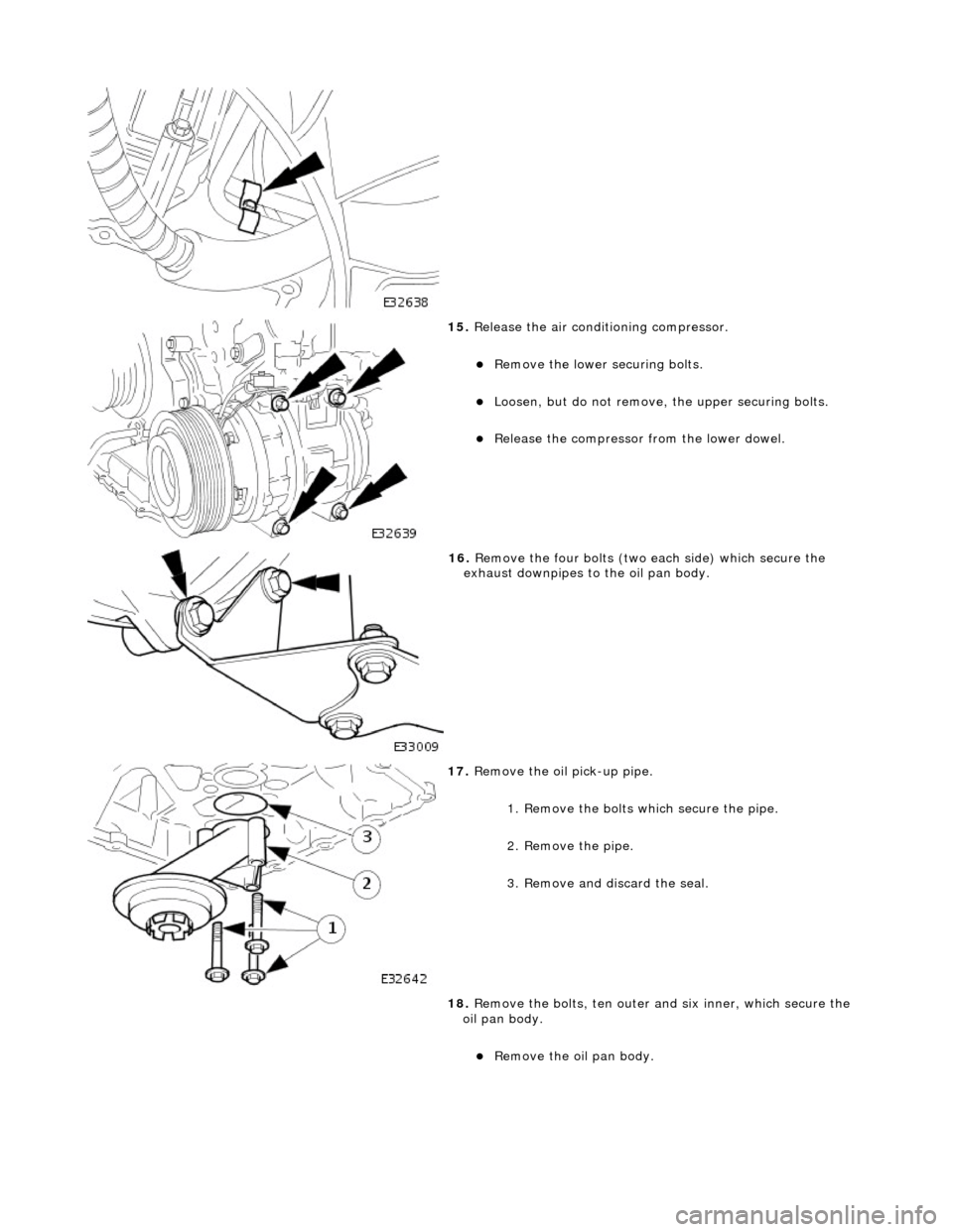
15. Release the air conditioning compressor.
пЃ¬Remove the lower securing bolts.
пЃ¬Loosen, but do not remove, th e upper securing bolts.
пЃ¬Release the compressor from the lower dowel.
16. Remove the four bolts (two each side) which secure the
exhaust downpipes to the oil pan body.
17. Remove the oil pick-up pipe.
1. Remove the bolts which secure the pipe.
2. Remove the pipe.
3. Remove and discard the seal.
18. Remove the bolts, ten outer an d six inner, which secure the
oil pan body.
пЃ¬Remove the oil pan body.
Page 837 of 2490
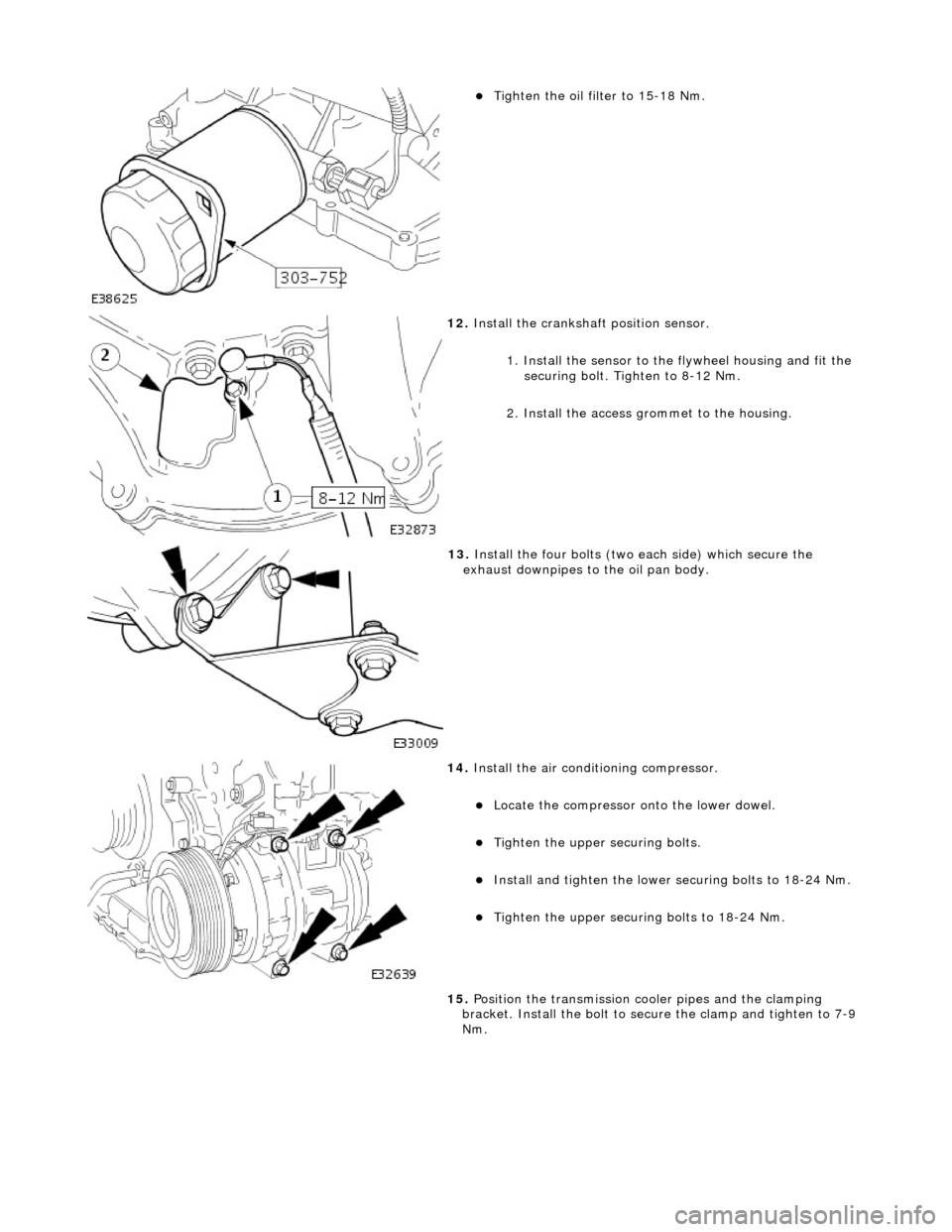
пЃ¬Tighten the oil filter to 15-18 Nm.
12. Install the crankshaft position sensor.
1. Install the sensor to the flywheel housing and fit the
securing bolt. Tighten to 8-12 Nm.
2. Install the access grommet to the housing.
13. Install the four bolts (two each side) which secure the
exhaust downpipes to the oil pan body.
14. Install the air conditioning compressor.
пЃ¬Locate the compressor onto the lower dowel.
пЃ¬Tighten the upper securing bolts.
пЃ¬Install and tighten the lower securing bolts to 18-24 Nm.
пЃ¬Tighten the upper securing bolts to 18-24 Nm.
15. Position the transmission cooler pipes and the clamping
bracket. Install the bolt to secu re the clamp and tighten to 7-9
Nm.
Page 841 of 2490
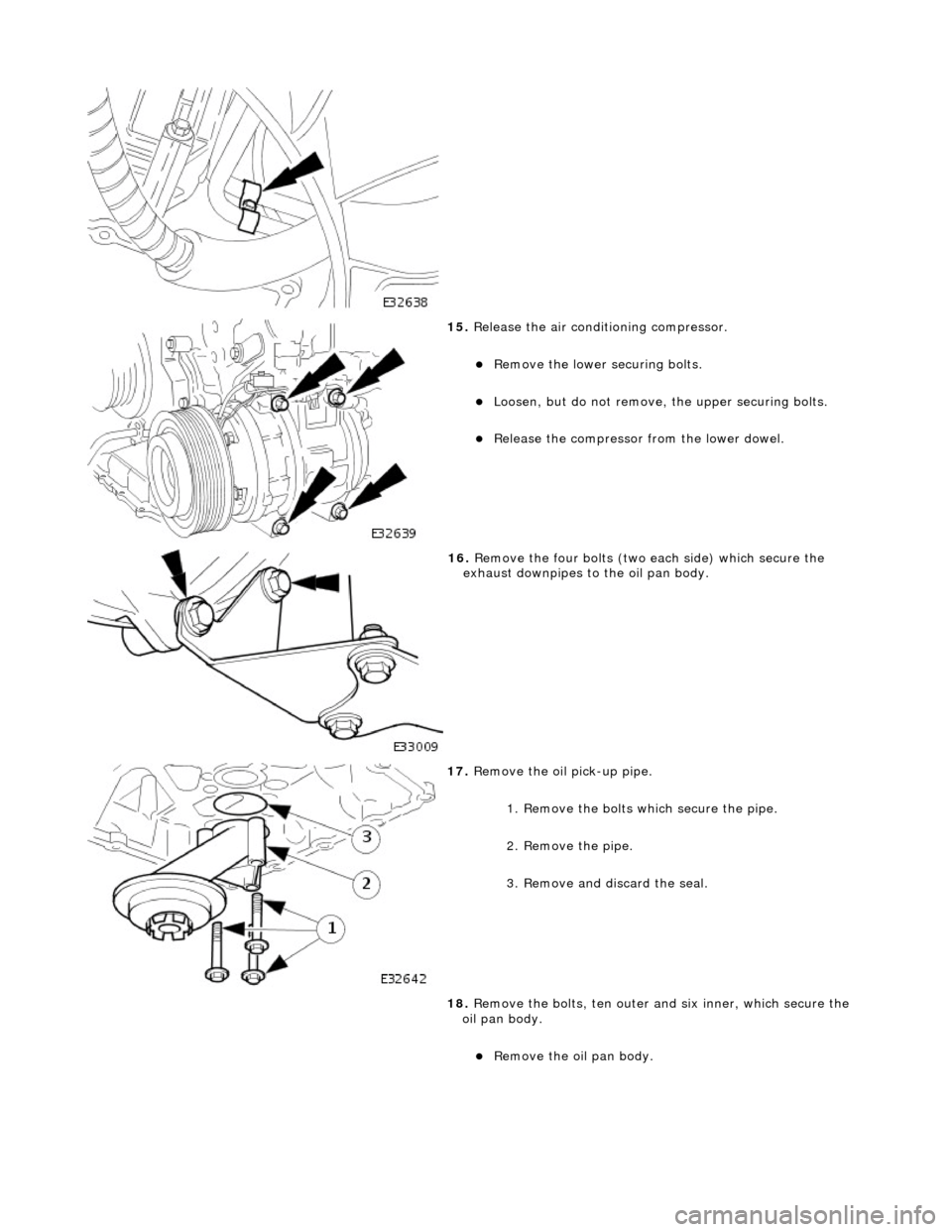
15. Release the air conditioning compressor.
пЃ¬Remove the lower securing bolts.
пЃ¬Loosen, but do not remove, th e upper securing bolts.
пЃ¬Release the compressor from the lower dowel.
16. Remove the four bolts (two each side) which secure the
exhaust downpipes to the oil pan body.
17. Remove the oil pick-up pipe.
1. Remove the bolts which secure the pipe.
2. Remove the pipe.
3. Remove and discard the seal.
18. Remove the bolts, ten outer an d six inner, which secure the
oil pan body.
пЃ¬Remove the oil pan body.
Page 846 of 2490

пЃ¬Tighten the oil filter to 15-18 Nm.
12. Install the crankshaft position sensor.
1. Install the sensor to the flywheel housing and fit the
securing bolt. Tighten to 8-12 Nm.
2. Install the access grommet to the housing.
пЃ¬Connect the harness clips to the oil pan body.
13. Install the four bolts (two each side) which secure the
exhaust downpipes to the oil pan body and transmission
casing.
14. Install the air conditioning compressor.
пЃ¬Locate the compressor onto the lower dowel.
пЃ¬Tighten the upper securing bolts.
пЃ¬Install and tighten the lower securing bolts to 18-24 Nm.
пЃ¬Tighten the upper securing bolts to 18-24 Nm.
15. Position the transmission cooler pipes and the clamping
bracket. Install the bolt to secu re the clamp and tighten to 7-9
Nm.