V8 supercharged JAGUAR X308 1998 2.G Workshop Manual
[x] Cancel search | Manufacturer: JAGUAR, Model Year: 1998, Model line: X308, Model: JAGUAR X308 1998 2.GPages: 2490, PDF Size: 69.81 MB
Page 46 of 2490
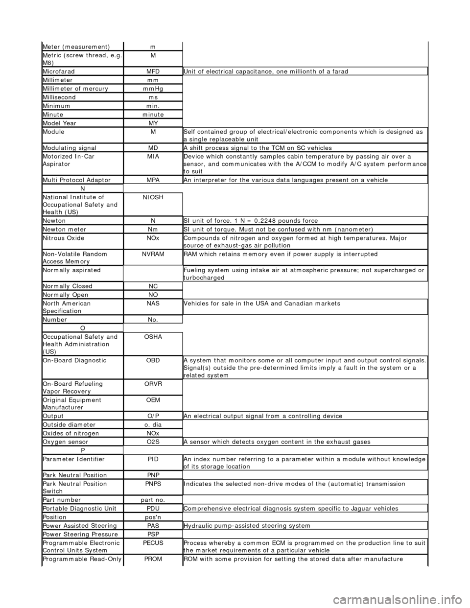
Meter (measurement)m
Me
tric (screw thread, e.g.
M8)
M
MicrofaradMFDUni t
of electrical capacitance, one millionth of a farad
Mi
ll
imeter
mm
Mi
ll
imeter of mercury
mm
Hg
Mill
isecond
ms
Min
i
mum
mi
n.
Min u
te
minut
e
Model YearMY
ModuleMSelf
contained group of electrical/electronic components which is designed as
a single replaceable unit
Modulating signalMDA sh
ift process signal to the TCM on SC vehicles
Motorized In
-Car
AspiratorMIAD e
vice which constantly samples cabi
n temperature by passing air over a
sensor, and communicates with the A/ CCM to modify A/C system performance
to suit
Mult i Prot
ocol Adaptor
MPAAn i
n
terpreter for the various data
languages present on a vehicle
N
Nati
onal Institute of
Occupational Safety and
Health (US)
NIO S
H
Ne
wto
n
NSI unit of force. 1
N = 0.224
8 pounds force
Ne
wto
n meter
NmSI unit of torque. Must not be
co
nfused with nm (nanometer)
Ni
tr
ous Oxide
NO
xCompounds of nit rogen and oxygen fo rmed at high temperatures. Major
sourc
e of exhaust-gas air pollution
No
n
-Volatile Random
Access Memory
NVR A
M
R
A
M which retains memory even
if power supply is interrupted
Normal
ly aspirated
F
u
eling system using intake air at atmo
spheric pressure; not supercharged or
turbocharged
N ormal
ly Closed
NC
N
o
rmally Open
NO
No
r
th American
Specification
NASVehicles f or sal
e in the USA and Canadian markets
Nu
mbe
r
No
.
O
Oc
cupational Safety and
Health Administration
(US)
OS H
A
O
n
-Board Diagnostic
OB
DA system that moni
tors some or all co
mputer input and output control signals.
Signal(s) outside the pre-de termined limits imply a fault in the system or a
related system
O n
-Board Refueling
Vapor Recovery
OR V
R
O
riginal
Equipment
Manufacturer
OE M
Outp
ut
O/
PAn electrical o u
tput signal from a controlling device
Ou
ts
ide diameter
o.
d
ia
O
xides of
nitrogen
NO
x
Oxygen senso
r
O2
SA s
ensor which detects oxygen content in the exhaust gases
P
Parameter Identifi
erPIDAn in
dex number referring to a parame
ter within a module without knowledge
of its storage location
Park N e
utral Position
PN
P
Park N e
utral Position
Switch
PN PSIndic
ates the selected non-drive modes of the (automatic) transmission
Part numberpart no.
Portable Diag
nostic Un
it
PD
UCompre hen
sive electrical diagnosis system specific to Jaguar vehicles
Posi
ti
on
po
s'n
Power As si
sted Steering
PASHydraul
i
c pump-assisted steering system
Power Steer
i
ng Pressure
PSP
Programmable Elect
r
onic
Control Units System
PECU SProcess whereb y
a common ECM is progra
mmed on the production line to suit
the market requirements of a particular vehicle
Programmable Read-O
nly
PROMRO
M with some provision for setting
the stored data after manufacture
Page 58 of 2490
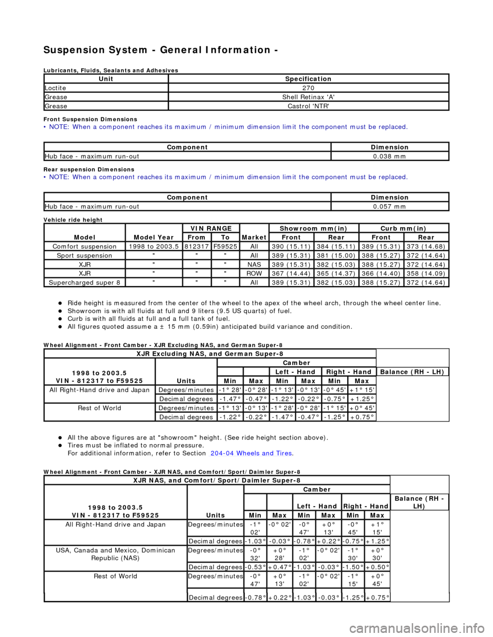
Suspension System - General Informatio
n -
Lubric
ants, Fluids, Sealants and Adhesives
Front Suspension Dimensions
• NO
TE: When a component reaches its maximum / minimum dimension limit the component must be replaced.
Rear sus
p
ension Dimensions
•
NO
TE: When a component reaches its maximum / minimum dimension limit the component must be replaced.
Vehicle ride
height
R i
de height is measured from
the center of the wheel to the apex of the wheel arch, through the wheel center line.
Showroom is with a
ll fluids at full an
d 9 liters (9.5 US quarts) of fuel.
Curb is
with all fluids at full and a full tank of fuel.
All f
i
gures quoted assume a ±
15 mm (0.59in) anticipated bu ild variance and condition.
Whee
l Alignment - Front Camber - XJR Excluding NAS, and German Super-8
Al l the above fi
gures
are at "showroom" height. (See ride height section above).
Tires must be infl
ated
to normal pressure.
For additional informat ion, refer to Section 204
-04
Wheels and Tires
.
Whe
e
l Alignment - Front Camber - XJR NAS, and Comfort/Sport/Daimler Super-8
UnitSp
ecification
Loctite27
0
Greas eShell Retin a
x 'A'
Greas
eCastro l 'NT
R'
Com
p
onent
Di
mensi
on
Hub face
-
maximum run-out
0.
03
8 mm
Com
p
onent
Di
mensi
on
Hub face
-
maximum run-out
0.
05
7 mm
Mod
e
l
Mod
e
l Year
V
I
N RANGE
Mark
et
Sh
owroom mm(in)
Curb mm(i
n)
FromToFron
t
RearFr
on
t
Rear
Com
f
ort suspension
1
998
to 2003.5
8
123
17
F
595
25
All3
90 (
15.11)
3
84 (
15.11)
3
89 (
15.31)
3
73 (
14.68)
Sport su
spe
nsion
"""All3
89 (
15.31)
3
81 (
15.00)
3
88 (
15.27)
3
72 (
14.64)
XJR"""NAS3
89 (
15.31)
3
82 (
15.03)
3
88 (
15.27)
3
72 (
14.64)
XJR"""RO
W367 (
14.44)
3
65 (
14.37)
3
66 (
14.40)
3
58 (
14.09)
Supercharged super 8"""All3
89 (
15.31)
3
82 (
15.03)
3
88 (
15.27)
3
72 (
14.64)
XJR
Excluding NAS, and German Super-8
1998 to
2003.5
VIN - 812317 to F59525
Units
Cambe r
Left
- Hand
Rig
h
t - Hand
Bal
a
nce (RH - LH)
MinMaxMinMaxMinMax
All Right-Hand driv
e and JapanDegrees
/minutes
-
1
° 28'
-0
°
28'
-
1
° 13'
-
0
° 13'
-0
° 45'+1 °
15'
Decimal degrees-1.
4
7°
-0
.4
7°
-1
.2
2°
-0.
2
2°
-0
.7
5°
+1
.25
°
R
e
st of World
De
grees
/minutes
-
1
° 13'
-0
°
13'
-
1
° 28'
-
0
° 28'
-1
° 15'+0 °
45'
Decimal degrees-1.
2
2°
-0
.2
2°
-1
.4
7°
-0.
4
7°
-1
.2
5°
+0
.75
°
XJR
NAS, and Comfort/Sport/Daimler Super-8
1
998 to
2003.5
VIN - 812317 to F59525
Units
Cambe r
Left
- Hand
Rig
h
t - Hand
Bal
a
nce (RH -
LH)
MinMaxMinMaxMinMax
All Right-Hand drive and JapanDegrees
/minutes
-1°
02'-0
° 02'
-0°
47'
+0°
13'
-0° 45'+1°
15'
Decimal degrees-1.0
3°
-0.0
3°
-0.7
8°
+0.22
°
-0.7
5°
+1.25
°
USA, Canada an
d Mexico,
Dominican
Republic (NAS)
De grees
/minutes
-0°
32 '+0 °
28'
-1 °
02'
-0 °
02'
-1°
30 '+0 °
30'
Decimal degrees-0. 5
3°
+0
.47
°
-1
.0
3°
-0
.0
3°
-1.
5
0°
+0
.50
°
R
e
st of World
De
grees
/minutes
-0°
47 '+0 °
13'
-1 °
02'
-0 °
02'
-1°
15 '+0 °
45'
Decimal degrees-0. 7
8°
+0
.22
°
-1
.0
3°
-0
.0
3°
-1.
2
5°
+0
.75
°
Page 167 of 2490
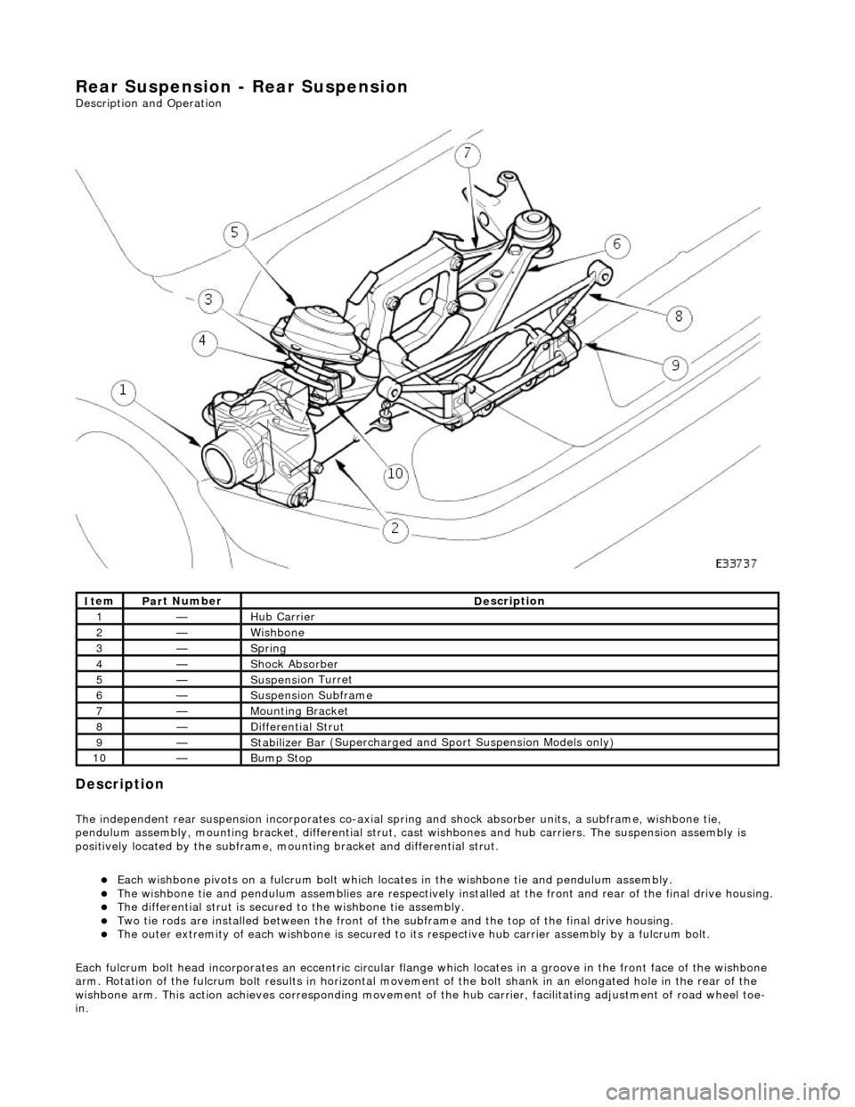
Rear
Suspension - Rear Suspension
Description an
d Operation
Description
The i
ndependent rear suspension incorporates co-axial sp
ring and shock absorber units, a subframe, wishbone tie,
pendulum assembly, mounting brac ket, differential strut, cast wishbones and hub carriers. The suspension assembly is
positively located by the subframe, mounting bracket and differential strut.
Each wi
shbone pivots on a fulcru
m bolt which locates in the wishbone tie and pendulum assembly.
The wish
bone tie and pendulum assemblies are respectively in
stalled at the front and rear of the final drive housing.
The differential
strut is secured to the wishbone tie assembly.
Two ti
e rods are installed between the front of the
subframe and the top of the final drive housing.
The ou
ter extremity of each wishbone
is secured to its respective hub carrier assembly by a fulcrum bolt.
Each fulcrum bolt head incorporates an ec centric circular flange which locates in a groove in the front face of the wishbone
arm. Rotation of the fulcrum bolt results in horizontal movement of the bolt shank in an elongated hole in the rear of the
wishbone arm. This acti on achieves corresponding movement of the hub carrier, facilita ting adjustment of road wheel toe-
in.
It
em
Par
t Number
De
scription
1—Hub Carrier
2—Wi
shbone
3—Sprin
g
4—Shock Absorber
5—Suspensi
on Turret
6—Suspensi
on Subframe
7—Moun
ting Bracket
8—D
ifferential Strut
9—Stabilizer Ba
r (Supercharged and
Sport Suspension Models only)
10—Bum
p Stop
Page 168 of 2490
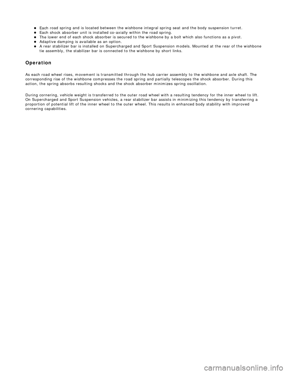
Each r
oad spring and is located between the wishbone in
tegral spring seat and the body suspension turret.
Each shoc
k absorber unit is installed
co-axially within the road spring.
The lo
wer end of each shock absorber is secured to the
wishbone by a bolt which also functions as a pivot.
Adaptive damping is av
ailable as an option.
A
rear stabi
lizer bar is installed on
Supercharged and Sport Suspension models . Mounted at the rear of the wishbone
tie assembly, the stabilizer bar is connected to the wishbone by short links.
Op era
tion
As each road wheel r
i
ses, move
ment is transmitted through th e hub carrier assembly to the wishbone and axle shaft. The
corresponding rise of the wishbone compre sses the road spring and partially telescopes the shock absorber. During this
action, the spring absorbs result ing shocks and the shock absorber minimizes spring oscillation.
During cornering, vehicle weight is transferred to the outer road wheel with a resulting tendency for the inner wheel to lift.
On Supercharged and Sport Suspension vehicl es, a rear stabilizer bar assists in minimizing this tendency by transferring a
proportion of potential lift of the inner wheel to the outer wheel. This results in enhanced body stability with improved
cornering capabilities.
Page 520 of 2490
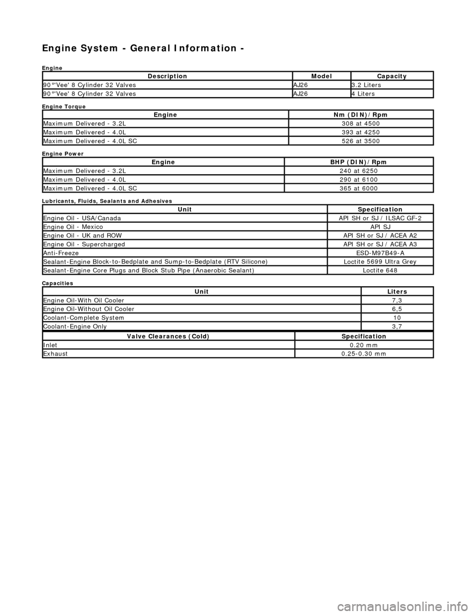
Engine System - General Inform
ation -
Eng
ine
Engine Torque
Engine Power
Lubricants, Fluids, Sealants and Adhesives
Capacities
Descr
iption
Mode
l
Capaci
ty
90
°'Ve
e' 8 Cylinder 32 Valves
AJ263.
2 L
iters
90
°'Ve
e' 8 Cylinder 32 Valves
AJ264 Li
te
rs
EngineNm (D
I
N)/Rpm
M
a
ximum Delivered - 3.2L
3
08 at
4500
M
a
ximum Delivered - 4.0L
3
93 at
4250
M
a
ximum Delivered - 4.0L SC
5
26 at
3500
EngineBH
P (D
IN)/Rpm
M
a
ximum Delivered - 3.2L
2
40 at
6250
M
a
ximum Delivered - 4.0L
2
90 at
6100
M
a
ximum Delivered - 4.0L SC
3
65 at
6000
UnitS
p
ecification
Engine Oil
-
USA/Canada
API SH or SJ
/ ILSAC G
F-2
Engine
Oil
- Mexico
API SJ
Engine
Oil
- UK and ROW
API SH or SJ
/ ACEA A2
Engine Oil -
Supercharged
API SH or SJ
/ ACEA A3
Anti-Freez
e
ESD-M97B
49
-A
Sealant-Engine B
l
ock-to-Bedplate an
d Sump-to-Bedplate (RTV Silicone)
Loct
ite 5699 Ultra Grey
Sealant-Engine
C
ore Plugs and Bloc
k Stub Pipe (Anaerobic Sealant)
Loctite 648
UnitLit
ers
Engine
Oil-W
ith Oil Cooler
7,
3
Engine Oil-W i
thout Oil Cooler
6,
5
Cool ant
-Complete System
10
Coo
lan
t-Engine Only
3,
7
Val v
e Clearances (Cold)
S
p
ecification
Inlet0.
20
mm
Exhaus
t0.25
-0.30 mm
Page 899 of 2490

16. Disconnect the air cleaner cover.
Remove the five clips which se cure the air cleaner cover.
17. Remove the intake tube / air flow meter / air cleaner cover
assembly.
1. Remove the intake tube / air flow meter / air cleaner
cover assembly.
2. Remove and discard the ru bber seal; air intake tube
to throttle body.
18. Remove the centre trim panel from the engine compartment.
1. Remove the left hand side enclosure panel.
2. Remove the centre trim panel.
19. Release the hoses (Quick Fit connections) from the expansion
tank, using 303 - 623.
1. Release the hose, expansion tank to thermostat housing (coolant outlet pipe on supercharged
engines).
Page 921 of 2490
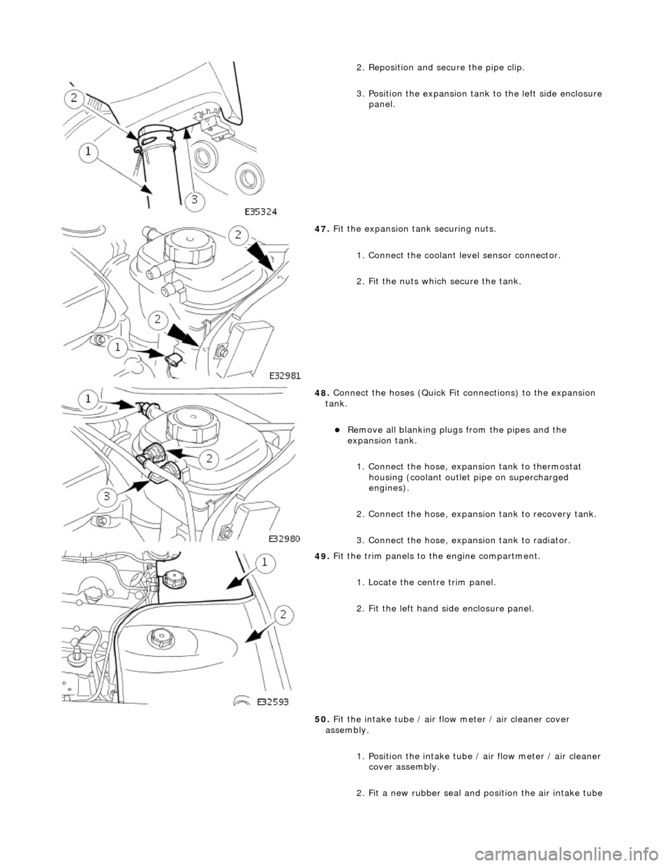
2
. Reposition and secure the pipe clip.
3. Position the expansion tank to the left side enclosure
panel.
47
.
Fit the expansion tank securing nuts.
1. Connect the coolant level sensor connector.
2. Fit the nuts which secure the tank.
48
.
Connect the hoses (Quick Fit connections) to the expansion
tank.
Remove all blanking plug s
from the pipes and the
expansion tank.
1. Connect the hose, expansion tank to thermostat housing (coolant outlet pipe on supercharged
engines).
2. Connect the hose, expansion tank to recovery tank.
3. Connect the hose, expansion tank to radiator.
49
.
Fit the trim panels to the engine compartment.
1. Locate the centre trim panel.
2. Fit the left hand side enclosure panel.
50. Fit the intake tube / air flow meter / air cleaner cover
assembly.
1. Position the intake tube / air flow meter / air cleaner
cover assembly.
2. Fit a new rubber seal and po sition the air intake tube
Page 924 of 2490
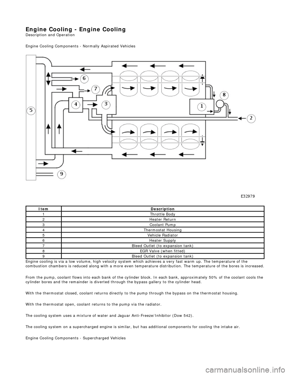
Engine Cooling
- Engine Cooling
Descr
i
ption and Operation
Engine Cooling Comp onents - Normally Aspirated Vehicles
Engine cooling is via a low volume, high velocity system which achieves a very fast warm up. The temperature of the
combustion chambers is reduced along with a more even temperature distribution. The temperature of the bores is increased.
F r
om the pump, coolant flows into each bank of the cylinder bl
ock. In each bank, approximately 50% of the coolant cools the
cylinder bores and the remainder is diverted th rough the bypass gallery to the cylinder head.
With the thermostat closed, coolant returns directly to the pump through the bypass on the thermostat housing.
With the thermostat open, coolant returns to the pump via the radiator.
The cooling system uses a mixture of water and Jaguar Anti-Freeze/Inhibitor (Dow 542).
The cooling system on a supercharged engine is similar, but has additional components for cooling the intake air.
Engine Cooling Co mponents - Supercharged Vehicles
ItemDescrip
tion
1Thr
ottle B
ody
2Hea
ter Return
3Coolant Pum p
4Ther
mostat Housing
5Vehicle Radia
t
or
6Hea
ter Su
pply
7Bleed
Outl
et (to expansion tank)
8EGR V
a
lve (when fitted)
9Bleed
Outl
et (to expansion tank)
Page 925 of 2490
T
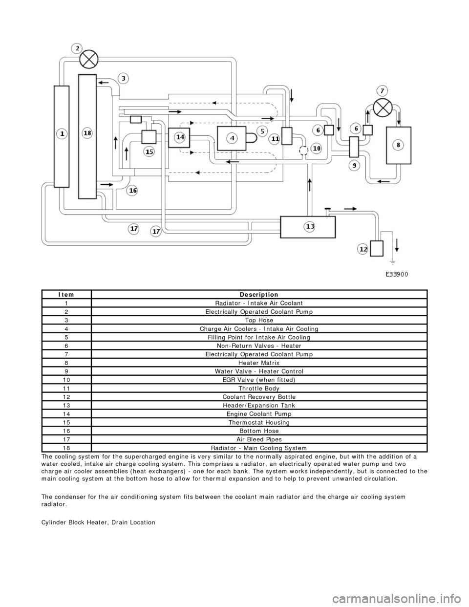
he cooling system for the supercharged engine is very similar
to the normally aspirated engine, but with the addition of a
water cooled, intake air charge cooling system. This comprises a radiator, an electrically operated water pump and two
charge air cooler assemblies (heat exchangers) - one for each bank. The system works independently, but is connected to the
main cooling system at the bottom hose to allow for therma l expansion and to help to prevent unwanted circulation.
The condenser for the air conditioning system fits between th e coolant main radiator and the charge air cooling system
radiator.
Cylinder Block Heater, Drain Location
ItemDe
scription
1Rad
iator - Intake Air Coolant
2Ele
ctrically Operated Coolant Pump
3Top Hose
4Charge Air Coo
lers -
Intake Air Cooling
5Fi
lling Point for Intake Air Cooling
6N
on-Return Valves - Heater
7Ele
ctrically Operated Coolant Pump
8Hea
ter Matrix
9Wate
r Valve - Heater Control
10EGR V
alve (when fitted)
11Thr
ottle Body
12Coolan
t Recovery Bottle
13H
eader/Expansion Tank
14Eng
ine Coolant Pump
15The
rmostat Housing
16Bottom
Hose
17Air Bleed
Pipes
18Rad
iator - Main Cooling System
Page 927 of 2490
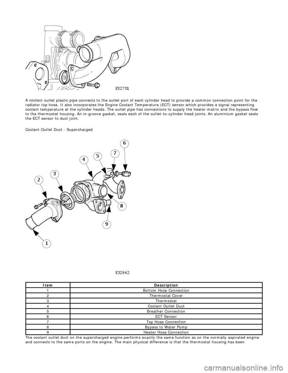
A coola
nt outlet plastic pipe connects to the outlet port of ea
ch cylinder head to provide a common connection point for the
radiator top hose. It also incorporates the Engine Coolant Te mperature (ECT) sensor which provides a signal representing
coolant temperature at the cylinder heads. The outlet pipe has connections to supply the heater matrix and the bypass flow
to the thermostat housing. An in-groove ga sket, seals each of the outlet-to-cylinder head joints. An aluminium gasket seals
the ECT sensor to duct joint.
Coolant Outlet Duct - Supercharged
The coolant outlet duct on the supercharged engine performs exactly the same function as on the normally aspirated engine
and connects to the same ports on the engine. The main physical difference is that the thermostat housing has been
ItemDe
scription
1Bottom
Hose Connection
2The
rmostat Cover
3The
rmostat
4Coolan
t Outlet Duct
5B
reather Connection
6ECT Se
nsor
7Top Hose Conn
ection
8Bypa
ss to Water Pump
9Hea
ter Hose Connection