ckp JAGUAR X308 1998 2.G Workshop Manual
[x] Cancel search | Manufacturer: JAGUAR, Model Year: 1998, Model line: X308, Model: JAGUAR X308 1998 2.GPages: 2490, PDF Size: 69.81 MB
Page 43 of 2490
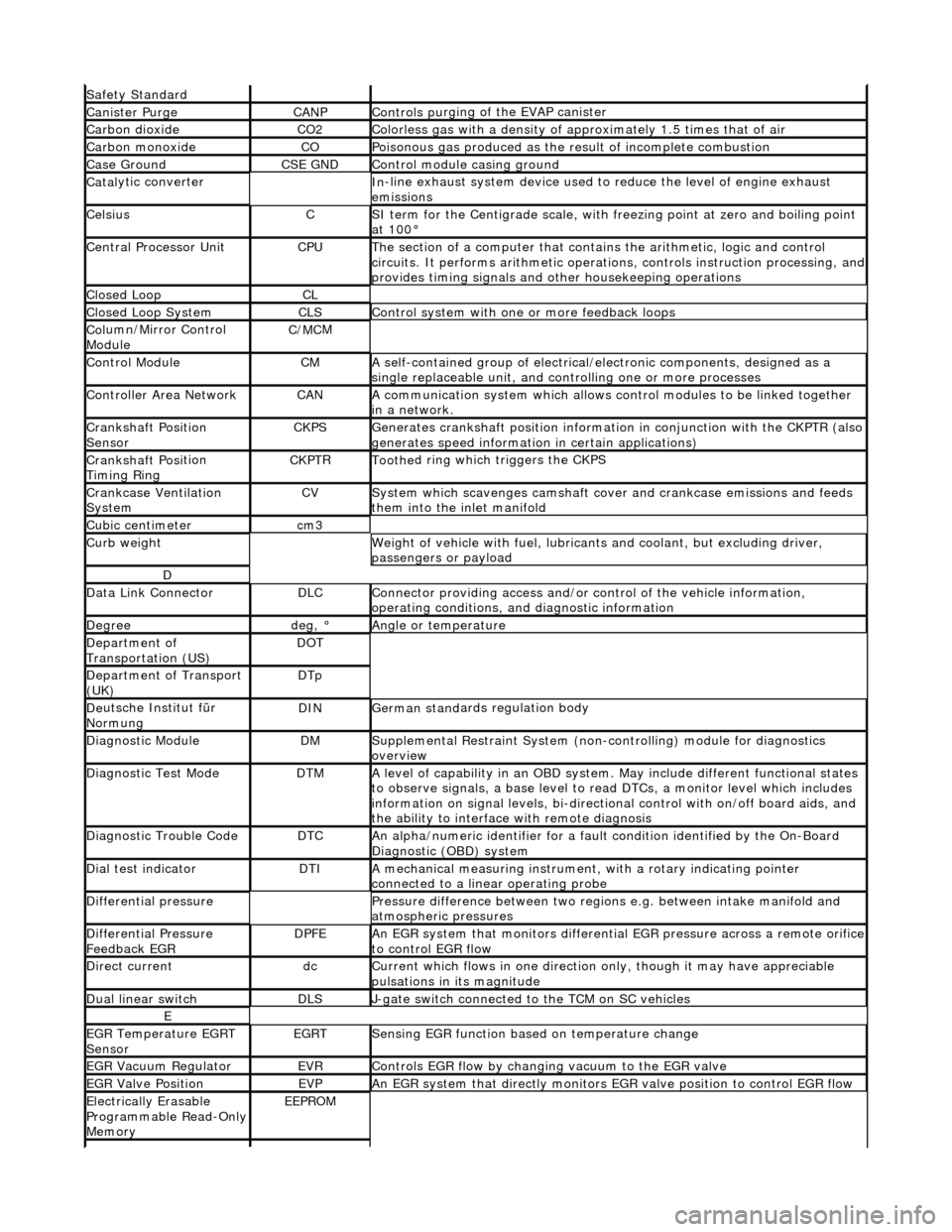
Safety Standard
Canister PurgeCANPControls pu
rging of the EVAP canister
Carbon dioxideCO2Colorless gas with
a density of a
pproximately 1.5 ti mes that of air
Carbon mon
oxide
COPoi
sonous gas produced as the re
sult of incomplete combustion
Case G
round
CSE GNDControl modu
le casing ground
Catal
ytic converter
In
-line exhaust system device used to reduce the level of engine exhaust
emissions
Ce
lsius
CSI ter
m for the Centigrade scale, with
freezing point at zero and boiling point
at 100°
Central
Processor Unit
CPUTh
e section of a computer that contai
ns the arithmetic, logic and control
circuits. It performs arithm etic operations, controls instruction processing, and
provides timing signals and other housekeeping operations
Cl
osed Loop
CL
Cl
osed Loop System
CLSControl
system with one
or more feedback loops
Col
umn/Mirror Control
Module
C/MC
M
Control ModuleCMA
self-contained group of electrical/electronic components, designed as a
single replaceable un it, and controlling one or more processes
Controll
er Area Network
CANA
communication system which allows control modules to be linked together
in a network.
Crankshaft Posi
tion
Sensor
CKPSGenerates crankshaft positi on informa
tion in conjunct
ion with the CKPTR (also
generates speed information in certain applications)
Crankshaft Posi
tion
Timing Ring
CKPT
R
Toothe
d ring which
triggers the CKPS
Crankcase Ventila
tion
System
CVSys
tem which scavenges camshaft cover and crankcase emissions and feeds
them into the inlet manifold
Cubic ce nt
imeter
cm
3
Curb weightWe
ight of vehicle with fuel, lubrican
ts and coolant, but excluding driver,
passengers or payload
D
Dat
a Link Connector
DLCConne
ctor providing access and/or control of the vehicle information,
operating conditions, and diagnostic information
De
gree
deg, °Angle or tempe
rature
D
epartment of
Transportation (US)
DO
T
D
epartment of Transport
(UK)
DTp
De
utsche In
stitut für
Normung
DINGerman stand
ards regulation body
Di
agnostic Module
DMSuppl
emental Restraint System (non-c
ontrolling) module for diagnostics
overview
Di
agnostic Test Mode
DTMA le
vel of capability in an OBD system.
May include different functional states
to observe signals, a base level to re ad DTCs, a monitor level which includes
information on signal levels, bi-directional control with on /off board aids, and
the ability to interface with remote diagnosis
Diagnostic Trouble CodeDTCAn al
pha/numeric identifier for a fault
condition identified by the On-Board
Diagnostic (OBD) system
D
ial test indicator
DTIA mechan
ical measuring
instrument, with a rotary indicating pointer
connected to a linear operating probe
D
ifferential pressure
Pressure di
fference betwee
n two regions e.g. between intake manifold and
atmospheric pressures
D
ifferential Pressure
Feedback EGR
DP
FE
An
EGR system that monito
rs differential EGR pressure across a remote orifice
to control EGR flow
D
irect current
dcCurrent which f
lows in on
e direction only, though it may have appreciable
pulsations in its magnitude
Du
al linear switch
DLSJ
-gate switch connected to the TCM on SC vehicles
E
EGR
Temperature EGRT
Sensor
EGRTSens
ing EGR function based on temperature change
EGR Vacu
um Regulator
EVRControls EGR
flow by changi
ng vacuum to the EGR valve
EGR Valve
Position
EVPAn EGR
system that direct
ly monitors EGR valve position to control EGR flow
Electrically E
rasable
Programmable Read-Only
Memory
EEP
ROM
Page 362 of 2490

In
stallation
6.
Clean all mating su rfaces and remove brake du
st, see
WARNING above.
7. Repeat above procedure to remo ve opposite side brake pads.
1. CAUTIO
N: Make sure grease does not contact brake-pad
friction surface or brake disc.
To prevent brake squeal apply grease to the shoulders of the
brake-pad backplate.
For additional information, refer to: Specifications
(206-0
4 Rear
Disc Brake, Specifications).
Apply a un iform
layer of grea
se to backplate shoulders,
making sure the whole sh oulder is covered.
2. CAUTIO
N: Make sure the brake pads are fitted with the
direction arrow following the direction of wheel rotation.
Make sure the brake pads are fi tted with the direction arrow
following the direction of wheel rotation.
3. CAUTI O
NS:
Retracting the caliper piston may cause the fluid reservoir
to over-flow. Remove brake flui d spillage immediately from paint
work, with clean water.
Make sure the brake pads are installed to the correct
orientation.
Make sure the brake pads ar e fitted with the direction
arrow following the direction of wheel rotation.
Note condition of pins an d 'R' clips and replace if
necessary.
Page 388 of 2490

In
stallation
6.
Clean all mating surfaces and remove brake du
st, see
WARNING above.
7. Repeat above procedure to remo ve opposite side brake pads.
1. CAUTIO
N: Make sure grease does not contact brake-pad
friction surface or brake disc.
To prevent brake squeal apply grease to the shoulders of the
brake-pad backplate.
For additional information, refer to: Specifications
(206-0
4 Rear
Disc Brake, Specifications).
Apply a un iform
layer of grea
se to backplate shoulders,
making sure the whole sh oulder is covered.
2. CAUTIO
N: Make sure the brake pads are fitted with the
direction arrow following the direction of wheel rotation.
Make sure the brake pads are fi tted with the direction arrow
following the direction of wheel rotation.
3. CAUTI O
NS:
Retracting the caliper piston may cause the fluid reservoir
to over-flow. Remove brake flui d spillage immediately from paint
work with clean water.
Make sure the brake pads are installed to the correct
orientation.
Make sure the brake pads ar e fitted with the direction
arrow following the direction of wheel rotation.
Note the condition of pins and replace if necessary.
• NOTE: Slowly retract caliper pistons.
Page 1022 of 2490
(ECT) se
nsor
Blocked part-load breather
(s
ervice action S474)
Injec
t
or leak
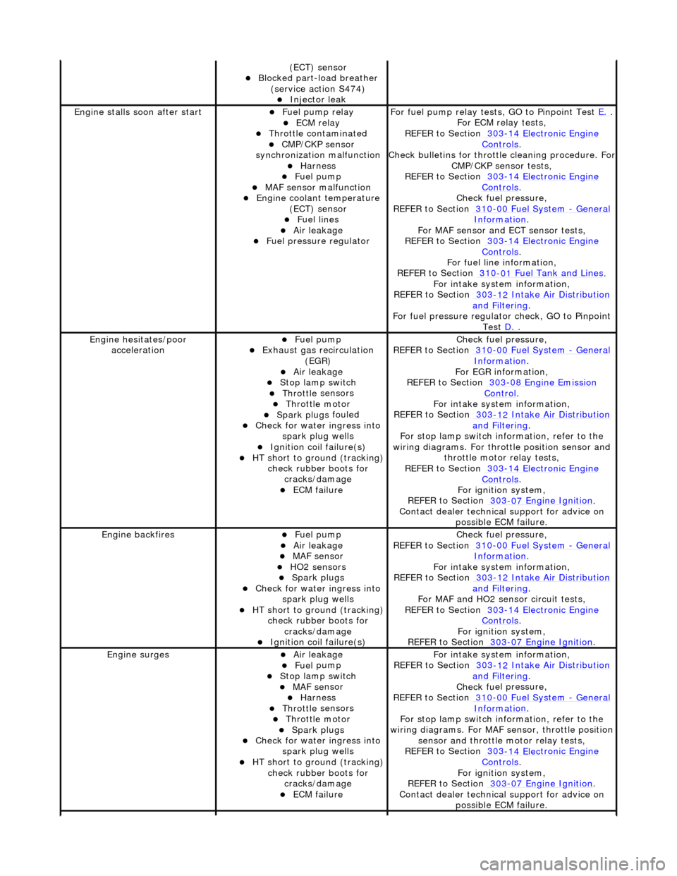
Engine stalls
soon
after start
F
u
el pump relay
ECM relay Thr
o
ttle contaminated
CMP/CKP sen
s
or
synchronization malfunction
Harness Fuel
pump
MAF
s
ensor malfunction
Engine coolan
t
temperature
(ECT) sensor
Fue l
lines
Air leakage Fu
el pressure regulator
F
o
r fuel pump relay tests,
GO to Pinpoint Test E.
.
F or ECM
relay tests,
REFER to Section 303
-14 Elec tronic En
gine
Controls.
Check bull etins for throttl
e cleaning procedure. For
CMP/CKP sensor tests,
REFER to Section 303
-14 Elec tronic En
gine
Controls.
Chec k fu
el pressure,
REFER to Section 310
-00 Fu
el System
- Ge
n
eral
Informati
o
n
.
F or MAF sensor and
ECT sensor tests,
REFER to Section 303
-14 Electronic En
gine
Controls.
For fuel l
ine information,
REFER to Section 310
-01
Fuel Tank and Lines
.
F or i
ntake system information,
REFER to Section 303
-1 2
Intake Air Distribution
and F
ilt
ering
.
F o
r fuel pressure regulato
r check, GO to Pinpoint
Test D.
.
Engine h e
sitates/poor
acceleration
Fue l
pump
Exhaus
t gas
recirculation
(EGR)
Air leakage Stop lamp swi t
ch
Throttl
e
sensors
Throttl
e
motor
Spark plugs
fouled
Check f
o
r water ingress into
spark plug wells
Ignition coil fail
ure(s)
HT sho
rt to ground (tracking)
check rubber
boots for
cracks/damage
ECM failu r
e
Chec
k fu
el pressure,
REFER to Section 310
-00 Fu
el System
- Ge
n
eral
Informati
o
n
.
F o
r EGR information,
REFER to Section 303
-08 En gin
e Emission
Control.
F or i
ntake system information,
REFER to Section 303
-1 2
Intake Air Distribution
and F
ilt
ering
.
F or stop l
amp switch in
formation, refer to the
wiring diagrams. For throttle position sensor and throttle motor relay tests,
REFER to Section 303
-14 Elec tronic En
gine
Controls.
For ign i
tion system,
REFER to Section 303
-07 En
gine Ignition
.
Contact dealer techn i
cal
support for advice on
possible ECM failure.
Engine ba ckfiresFuel
pump
Air leakage MAF s
e
nsor
HO2 sensors Spark plugs
Check fo
r water ingress into
spark plug wells
HT short to ground (tracking) check rubber
boots for
cracks/damage
Ignition coil fail
ure(s)
Chec
k fu
el pressure,
REFER to Section 310
-00 Fu
el System
- Ge
n
eral
Informati
o
n
.
F or i
ntake system information,
REFER to Section 303
-1 2
Intake Air Distribution
and F
ilt
ering
.
For MAF and HO2
sensor circuit tests,
REFER to Section 303
-14 Electronic En
gine
Controls.
For igni
tion system,
REFER to Section 303
-07 En
gine Ignition
.
Engine
s
urges
Air leakage Fue
l
pump
Stop lamp swi
t
ch
MAF s
e
nsor
Harness Throttl
e
sensors
Throttl
e
motor
Spark plugs
Check fo
r water ingress into
spark plug wells
HT sho rt to ground (tracking)
check rubber
boots for
cracks/damage
ECM failu r
e
F
or i
ntake system information,
REFER to Section 303
-1 2
Intake Air Distribution
and F
ilt
ering
.
Chec k fu
el pressure,
REFER to Section 310
-00 Fu
el System
- Gen
e
ral
Informati
o
n
.
F or stop l
amp switch in
formation, refer to the
wiring diagrams. For MAF se nsor, throttle position
sensor and throttle motor relay tests,
REFER to Section 303
-14 Elec tronic En
gine
Controls.
For ign i
tion system,
REFER to Section 303
-07 En
gine Ignition
.
Contact dealer techn i
cal
support for advice on
possible ECM failure.
Page 1178 of 2490

Throttle Position (TP) Sensor
Location
P
arts List
sen
d
s the ECM a signal indica
ting throttle plate angle
is
the main input to the ECM from the driver
i
s
a dual Hall effect devi
ce mounted on the motor en d of the throttle body
Two additional sensors are attached to the throttle body to provide additional feedback to the ECM: a mechanical guard
position sensor and an accelerator pedal position sensor.
Cam s
haft Position (CMP) Sensor
sen
d
s the ECM a signal indicating camshaft po
sition for fuel synchronization purposes
is
a variable reluctance device mounted on bank 2 cylinder side face
generates a signal when the ri
ng
fitted to the bank 2 inlet
camshaft passes the sensor
Cranksha
ft Position (CKP) Sensor
i
s
a variable reluctance device
mounted on the engine oil pan
Ite
m
Par
t
Number
De
scr
iption
1—Acce
le
rator pedal and mechanic
al guard position sensors
2—Throttle
(blade)
position sensor
Page 1191 of 2490
Fue
l pump
Engine coolan
t temperature
(ECT) sensor
Blocked part-load breather (
service action S474)
Injec
tor leak
Emiss
ions
.
Check bull
etins for throttle cleaning procedure.
Check fuel pressure. For ECT sensor circuit tests,
GO to Pinpoint Test C.
. Refer to Servi
ce action
S474 for part-load breather procedure. For
injector leak test, Refer to technical service bulletin 303-39.
D
ifficult to start after hot
soak (vehicle standing
after engine has reached operating temperature)
Roc
hester valve
Thr
ottle contaminated
Purge
valve
Fue
l pump
Engine coolan
t temperature
(ECT) sensor
Blocked part-load breather (
service action S474)
Injec
tor leak
Engine cranks too
fa
st/slow
Batt
ery
Starter relay Harness Cyl
inder compression loss
(NA short term only. Refer to technical service bulletin; 303-39)
R
efer to service action
S491
F
or battery information,
REFER to Section 414
-0
1 Battery, Mounting and
Cables.
F
or starting system.
REFER to Section 303
-06 Sta
rting System
.
R
efer to technical servic
e bulletins and service
actions.
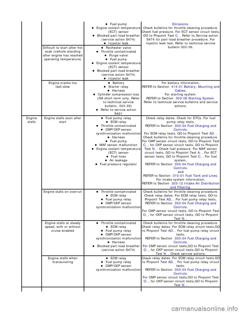
Engine
stalls
Engine st
alls soon after
start
F
uel pump relay
ECM relay Thr
ottle contaminated
CMP/CKP sen
sor
synchronization malfunction
Harness Fue
l pump
MAF
sensor malfunction
Engine coolan
t temperature
(ECT) sensor
Fue
l lines
Air leakage
F
uel pressure regulator
Check r
elay dates. Chec
k for DTCs. For fuel
pump relay tests,
REFER to Section 303
-0
4 Fuel Charging and
Controls.
F
or ECM relay tests, GO to Pinpoint Test
AD.
.
Check bull
etins for throttle cleaning procedure.
For CMP sensor circuit test s, GO to Pinpoint Test
C.
, for
CKP sensor circuit tests, GO to Pinpoint
Test N.
. Check fuel
pressure. For MAF sensor
circuit tests, GO to Pinpoint Test A.
. For EC
T
sensor tests, GO to Pinpoint Test C.
. F
or fuel
system,
REFER to Section 303
-0
4 Fuel Charging and
Controls.
and
REF
ER to Section 310
-0
1 Fuel Tank and Lines
. F
or intake system information,
REFER to Section 303
-1
2 Intake Air Distribution
and F
iltering
.
Engine
stalls on overrun
Thr
ottle contaminated
ECM relay F
uel pump relay
CMP/CKP sen
sor
synchronization malfunction
Check bull
etins for throttle cleaning procedure.
Check relay dates. For ECM relay tests, GO to Pinpoint Test AD.
. F
or fuel pump relay tests,
REFER to Section 303
-0
4 Fuel Charging and
Controls.
F
or CMP sensor circuit test
s, GO to Pinpoint Test
O.
, for
CKP sensor circuit tests, GO to Pinpoint
Test N.
.
E
ngine stalls at steady
speed, with or without cruise enabled
Thr
ottle contaminated
ECM relay F
uel pump relay
CMP/CKP sen
sor
synchronization malfunction
Harness Blocked part-load breather
(
service action S474)
Check bull
etins for throttle cleaning procedure.
Check relay dates. For EC M relay circuit tests,GO
to Pinpoint Test AD.
. F
or fuel pump relay circuit
tests,
REFER to Section 303
-0
4 Fuel Charging and
Controls.
F
or CMP sensor circuit test
s,GO to Pinpoint Test
O.
, for
CKP sensor circuit tests,GO to Pinpoint
Test N.
. Che
ck service actions.
Engine st
alls when
maneuvering
ECM relay F
uel pump relay
CMP/CKP sen
sor
synchronization malfunction
Check r
elay dates. For EC
M relay circuit tests,GO
to Pinpoint Test AD.
. F
or fuel pump relay circuit
tests,
REFER to Section 303
-0
4 Fuel Charging and
Controls.
F
or CMP sensor circuit test
s,GO to Pinpoint Test
O.
, for
CKP sensor circuit tests,GO to Pinpoint
Test N.
.
Page 1200 of 2490
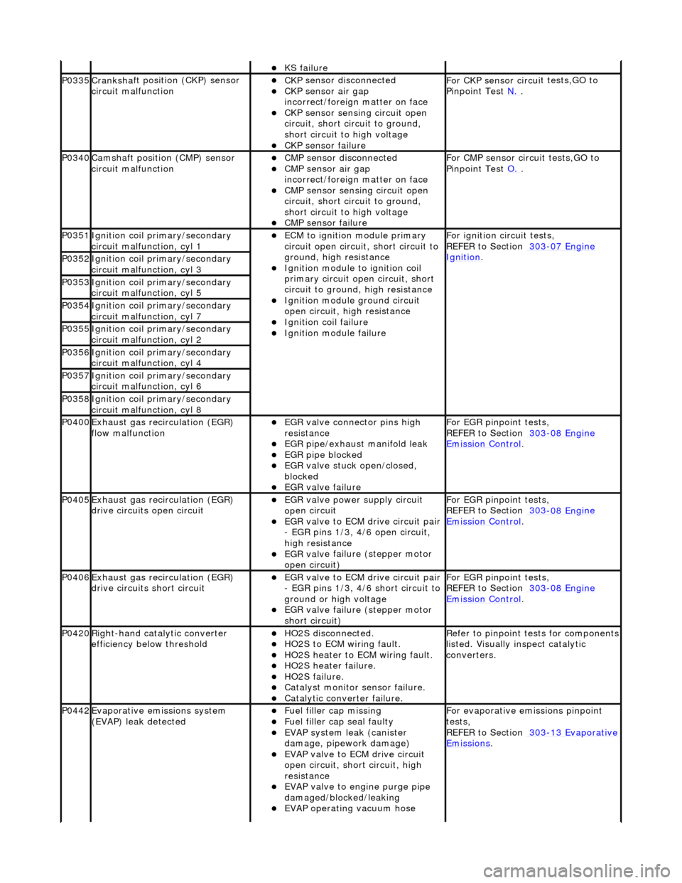
KS fail
ure
P0335Cranksh
a
ft positi
on (CKP) sensor
circuit malfunction
CK P
sensor disconnected
CKP sensor air gap
i
n
correct/foreign matter on face
CKP sensor sen
s
ing circuit open
circuit, short circuit to ground,
short circuit to high voltage
CKP s e
nsor failure
F
or CKP sensor circ ui
t tests,GO to
Pinpoint Test N.
.
P0340Camshaft position
(CMP) sensor
circuit malfunction
CM P
sensor disconnected
CMP sensor air gap
i
n
correct/foreign matter on face
CMP sensor sen
s
ing circuit open
circuit, short circuit to ground,
short circuit to high voltage
CMP s e
nsor failure
F
or CMP sensor circ ui
t tests,GO to
Pinpoint Test O.
.
P0351Igniti
on coil primary/secondary
circuit malfunction, cyl 1
ECM to ignit
ion module primary
circuit open circuit, short circuit to
ground, high resistance
Igniti
on module to ignition coil
primary circuit open circuit, short
circuit to ground, high resistance
Ignition modu le
ground circuit
open circuit, hi gh resistance
Ignition coil fail
ure
Ignition modul
e
failure
F
o
r ignition circuit tests,
REFER to Section 303
-07 En
gine
Ignition. P0352Ignit
i
on coil primary/secondary
circuit malfunction, cyl 3
P0353Ignit i
on coil primary/secondary
circuit malfunction, cyl 5
P0354Ignit i
on coil primary/secondary
circuit malfunction, cyl 7
P0355Ignit i
on coil primary/secondary
circuit malfunction, cyl 2
P0356Ignit i
on coil primary/secondary
circuit malfunction, cyl 4
P0357Ignit i
on coil primary/secondary
circuit malfunction, cyl 6
P0358Ignit i
on coil primary/secondary
circuit malfunction, cyl 8
P0400Exhaus t gas
recirculation (EGR)
flow malfunction
EGR valve c
onnector pins high
resistance
EGR pipe/exhaust manifol
d leak
EGR pipe blocke
d
EGR valve st
uck open/closed,
blocked
EGR valve fai
lure
For EGR
pinpoint t
ests,
REFER to Section 303
-08 En
gine
Emission Control.
P0405Exhaus
t gas
recirculation (EGR)
drive circuits open circuit
EGR valve power supply circuit
o p
en circuit
EGR valve t
o
ECM drive circuit pair
- EGR pins 1/3, 4/6 open circuit,
high resistance
EGR val v
e failure (stepper motor
open circuit)
For EGR pinpoint t
ests,
REFER to Section 303
-08 En
gine
Emissi
on Control.
P0406Exhaus t gas
recirculation (EGR)
drive circuits short circuit
EGR valve t o
ECM drive circuit pair
- EGR pins 1/3, 4/6 short circuit to
ground or high voltage
EGR val v
e failure (stepper motor
short circuit)
For EGR pinpoint t
ests,
REFER to Section 303
-08 En
gine
Emissi
on Control.
P0420Right-
hand catalytic converter
efficiency below threshold
HO2S di
sconnected.
HO2
S
to ECM wiring fault.
HO2
S
heater to ECM wiring fault.
HO2
S
heater failure.
HO2
S
failure.
Cat
a
lyst monitor sensor failure.
Catal
y
tic converter failure.
R
e
fer to pinpoint tests for components
listed. Visually inspect catalytic
converters.
P0442Evaporati v
e emissions system
(EVAP) leak detected
Fue l
filler cap missing
Fu
el filler cap seal faulty
EVAP system
leak (can
ister
damage, pipework damage)
EVAP v a
lve to ECM drive circuit
open circuit, short circuit, high
resistance
EVAP valve to engine pu rge pipe
damaged/blocked/leaking
EVAP ope r
ating vacuum hose
F
or evaporati
ve emissions pinpoint
tests,
REFER to Section 303
-1 3
Evaporative
Emissi
ons
.
Page 1205 of 2490
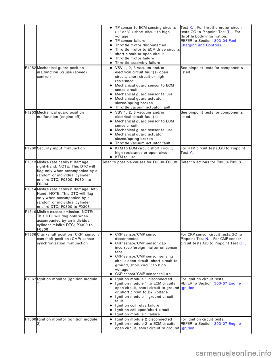
TP se
nsor to ECM sensing circuits
('1' or '2') short circuit to high
voltage
TP sensor
failure
Throttl
e motor disconnected
Th
rottle motor to ECM drive circuits
short circuit or open circuit
Throttl
e motor failure
Throttl
e assembly failure
Test
K. . F
or throttle motor circuit
tests,GO to Pinpoint Test T.
. For
throttle body i
nformation,
REFER to Section 303
-04
Fuel
Charging and Con
trols
.
P1252Mec
hanical gu
ard position
malfunction (cruise (speed)
control)
VSV 1, 2, 3 v
acuum and/or
electrical circuit fault(s) open
circuit, short circuit or high
resistance
Mechanica
l guard sensor to ECM
sense circuit
Mechanica
l guard sensor failure
Mechanica
l guard actuator
siezed/spring broken
Throttl
e vacuum actuator fault
Se
e pinpoint tests for components
listed.
P1253Mec
hanical gu
ard position
malfunction (engine off)
VSV 1, 2, 3 v
acuum and/or
electrical circuit fault(s)
Mechanica
l guard sensor to ECM
sense circuit
Mechanica
l guard sensor failure
Mechanica
l guard actuator
siezed/spring broken
Throttl
e vacuum actuator fault
Se
e pinpoint tests for components
listed.
P1260Se
curity input malfunction
K
TM to ECM circuit short circuit,
high resistance or open circuit
KTM failu
re
F
or KTM circuit tests,GO to Pinpoint
Test Y.
.
P1313M
isfire rate catalyst damage,
right-hand. NOTE: This DTC will
flag only when accompanied by a
random or individual cylinder
misfire DTC; P0300, P0301 to
P0304
R
efer to possible causes for P0300-P0308
R
efer to actions for P0300-P0308.
P1314Mi
sfire rate catalyst damage, left-
Hand: NOTE. This DTC will flag
only when accompanied by a
random or individual cylinder
misfire DTC; P0300 to P0308
P1316M
isfire excess emission. NOTE:
This DTC will flag only when
accompanied by an individual
cylinder misfire DTC; P0300 to
P0308
P1336Cranksh
aft position
(CKP) sensor /
camshaft position (CMP) sensor
synchronization malfunction
CKP s
ensor/CMP sensor
disconnected
CKP sensor/CM
P sensor gap
incorrect/foreign matter on sensor
face
CKP s
ensor/CMP sensor sensing
circuit open circuit, short circuit to
ground, short circuit to high
voltage
CKP s
ensor/CMP sensor failure
F
or CKP sensor circ
uit tests,GO to
Pinpoint Test N.
. For CM
P sensor
circuit tests,GO to Pinpoint Test O.
.
P1367Ignit
ion monitor (ignition module
1)
Ignition modu
le
1 disconnected
Ignition modul
e 1 to ECM circuits
open circuit, short circuit to ground
or short circuit to B+ voltage
Ignition modul
e 1 ground circuit
fault
Ignition coil
relay failure
Ignition coil
open/short circuit
Ignition modul
e 1 failure
F
or ignition circuit tests,
REFER to Section 303
-07
Engine
Ignition.
P1368Ignit
ion monitor (ignition module
2)
Ignition modu
le
2 disconnected
Ignition modul
e 2 to ECM circuits
open circuit, short circuit to ground
F
or ignition circuit tests,
REFER to Section 303
-07
Engine
Ignition.
Page 1216 of 2490
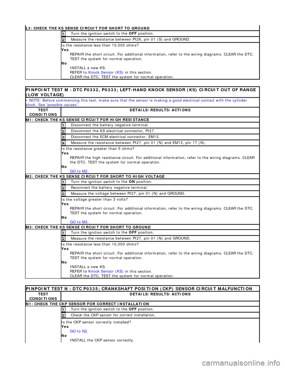
L3
: CHECK THE KS SENSE CIRCUIT FOR SHORT TO GROUND
Turn the ignition swi
t
ch to the OFF
position.
1
Me
asure the resistance between PI26, pin 01 (S) and GROUND.
2
Is
t
he resistance less than 10,000 ohms?
Yes REPAIR the short circuit. For addi tional information, refer to the wiring diagrams. CLEAR the DTC.
TEST the system for normal operation.
No INSTALL a new KS.
REFER to Knock Sensor (KS)
in this
section.
CLEAR the DTC. TEST the system for normal operation.
P INPOINT TES
T M : DTC P0332, P0333; LEFT-H
AND KNOCK SENSOR (KS) CIRCUIT OUT OF RANGE
(LOW VOLTAGE)
•
NOTE: Before commencing this
test, make sure that the sensor is making a good electrical contact with the cylinder
block. See 'possible causes'.
TE S
T
CONDITIONS
D E
TAILS/RESULTS/ACTIONS
M1: CHECK THE KS SEN
S
E CI
RCUIT FOR HIGH RESISTANCE
Di
sc
onnect the battery negative terminal.
1
Di
sc
onnect the KS electrical connector, PI27.
2
D
i
sconnect the ECM electrical connector, EM13.
3
M
e
asure the resistance between PI27, pin 01 (N) and EM13, pin 17 (N).
4
Is th
e res
istance greater than 5 ohms?
Yes REPAIR the high resistance circui t. For additional information, refer to the wiring diagrams. CLEAR
the DTC. TEST the system for normal operation.
No GO to M2
.
M2: CHECK TH
E KS SENSE CIRCUIT FOR SHORT TO HIGH VOLTAGE
Turn the ignition swi
t
ch to the ON
position.
1
Re
connect the battery negative terminal.
2
Meas
ure t
he voltage between PI27, pin 01 (N) and GROUND.
3
Is th
e volt
age greater than 3 volts?
Yes REPAIR the short circuit. For addi tional information, refer to the wiring diagrams. CLEAR the DTC.
TEST the system for normal operation.
No GO to M3
.
M3: CHECK TH
E KS SENSE CIRCUIT FOR SHORT TO GROUND
Turn the ignition swi
t
ch to the OFF
position.
1
Measure t
he resistance between PI27, pin 01 (N) and GROUND.
2
Is
t
he resistance less than 10,000 ohms?
Yes REPAIR the short circuit. For addi tional information, refer to the wiring diagrams. CLEAR the DTC.
TEST the system for normal operation.
No INSTALL a new KS.
REFER to Knock Sensor (KS)
in this
section.
CLEAR the DTC. TEST the system for normal operation.
PINPOINT TEST N : DTC P0335;
CRANKSHAFT POSITION (CKP) SENSOR CIRCUIT MALFUNCTION
TE
S
T
CONDITIONS
D E
TAILS/RESULTS/ACTIONS
N
1: CH
ECK THE CKP SENSOR FOR CORRECT INSTALLATION
Turn the ignition swi
t
ch to the OFF
position.
1
Check the CKP sen
sor fo
r correct installation.
2
Is the CK
P sensor correctly installed?
Yes GO to N2
.
No
INST
ALL the CKP sensor correctly.
Page 1217 of 2490
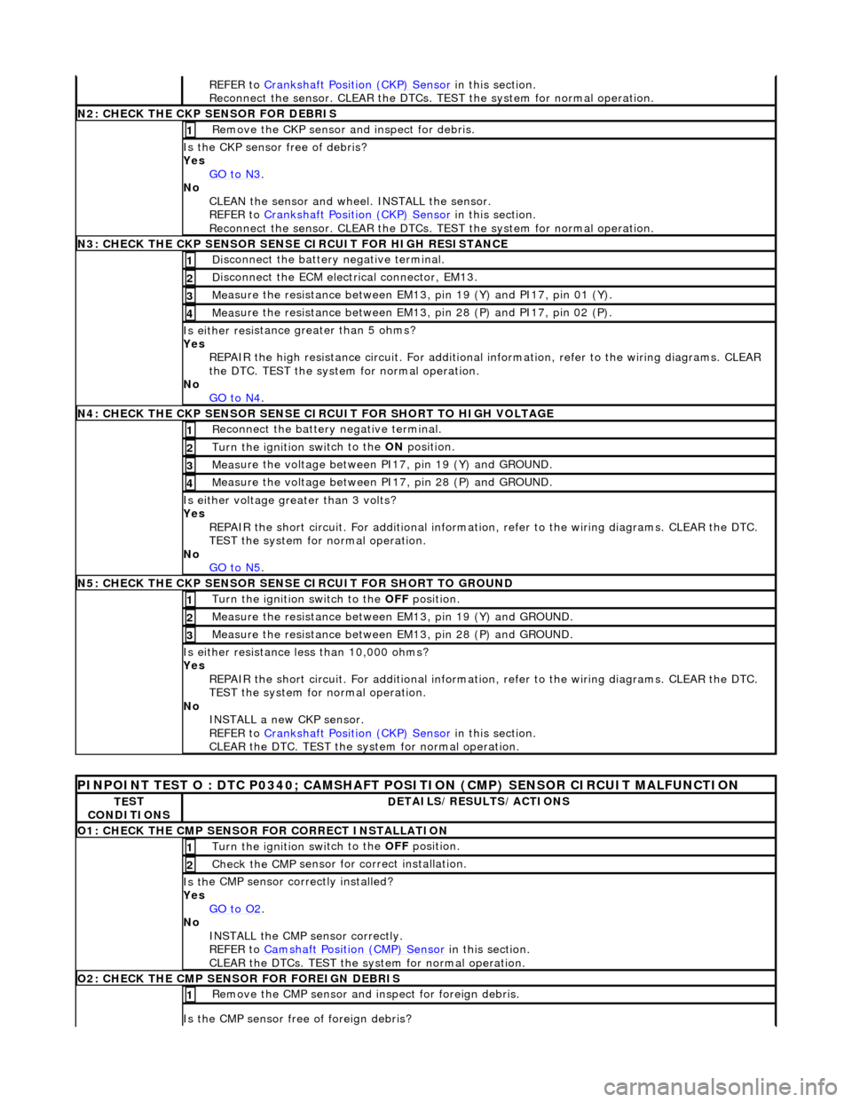
REF
ER to
Crankshaft Position (CKP) Sensor
in this section.
Reconnect the sensor. CLEAR the DTCs. TE ST the system for normal operation.
N
2: CHECK THE CKP SENSOR FOR DEBRIS
Re
move the CKP sensor
and inspect for debris.
1
Is the CKP sensor free of
debris?
Yes GO to N3
.
No
CLEAN the sensor and whee l. INSTALL the sensor.
REFER to Crankshaft Position (CKP) Sensor
in this section.
Reconnect the sensor. CLEAR the DTCs. TE ST the system for normal operation.
N
3: CHECK THE CKP SENSOR SENSE CIRCUIT FOR HIGH RESISTANCE
Di
sconnect the battery negative terminal.
1
D
isconnect the ECM electrical connector, EM13.
2
Me
asure the resistance between EM13, pin 19 (Y) and PI17, pin 01 (Y).
3
Meas
ure the resistance between EM13, pin 28 (P) and PI17, pin 02 (P).
4
Is either resi
stance
greater than 5 ohms?
Yes REPAIR the high resistance circui t. For additional information, refer to the wiring diagrams. CLEAR
the DTC. TEST the system for normal operation.
No GO to N4
.
N
4: CHECK THE CKP SENSOR SENSE CI
RCUIT FOR SHORT TO HIGH VOLTAGE
R
econnect the battery negative terminal.
1
Turn the ignition swi
tch to the ON
position.
2
Meas
ure the voltage between PI17, pin 19 (Y) and GROUND.
3
M
easure the voltage between PI17, pin 28 (P) and GROUND.
4
Is ei
ther voltage greater than 3 volts?
Yes REPAIR the short circuit. For addi tional information, refer to the wiring diagrams. CLEAR the DTC.
TEST the system for normal operation.
No GO to N5
.
N
5: CHECK THE CKP SENSOR SENSE CIRCUIT FOR SHORT TO GROUND
Turn the ignition swi
tch to the OFF
position.
1
Meas
ure the resistance between EM13, pin 19 (Y) and GROUND.
2
Meas
ure the resistance between EM13, pin 28 (P) and GROUND.
3
Is either resi
stance
less than 10,000 ohms?
Yes REPAIR the short circuit. For addi tional information, refer to the wiring diagrams. CLEAR the DTC.
TEST the system for normal operation.
No INSTALL a new CKP sensor.
REFER to Crankshaft Position (CKP) Sensor
in this section.
CLEAR the DTC. TEST the system for normal operation.
P
INPOINT TEST O : DTC P0340;
CAMSHAFT POSITION (CMP) SENSOR CIRCUIT MALFUNCTION
TE
ST
CONDITIONS
D
ETAILS/RESULTS/ACTIONS
O1: CHECK THE CM
P SENSOR FOR CORRECT INSTALLATION
Turn the ignition swi
tch to the OFF
position.
1
Check the CMP
sensor fo
r correct installation.
2
Is th
e CMP sensor correctly installed?
Yes GO to O2
.
No
INSTALL the CMP sensor correctly.
REFER to Camshaft Position (CMP) Sensor
in this section.
CLEAR the DTCs. TEST the system for normal operation.
O2: CHECK THE CM
P SENSOR FOR FOREIGN DEBRIS
Re
move the CMP sensor and
inspect for foreign debris.
1
Is the CMP sensor free of
foreign debris?