head gasket JAGUAR X308 1998 2.G Workshop Manual
[x] Cancel search | Manufacturer: JAGUAR, Model Year: 1998, Model line: X308, Model: JAGUAR X308 1998 2.GPages: 2490, PDF Size: 69.81 MB
Page 9 of 2490

303‐01: En gine
Diagnos
is
and Testing
Engine
DTC P1392 VVT solenoid A circuit low input
DTC P1397 VVT solenoid B circuit low input
DTC P1393 VVT solenoid A circuit high input
DTC P1398 VVT solenoid B circuit high input
DTC P1396 VVT solenoid B malfunction
Pinpoint test A: P13
92 (P1397) VVT solenoid circuit low input
Pinpoint test B: P1393 (P1398) VVT solenoid circuit high input
Pinpoint test C: P1396 VVT solenoid malfunction
In
‐Vehicle Repair
Connecting
Rod Bearings (12.17.16)
Crankshaft
Front Seal Vehicles Without: Supe
rcharger (12.21.14)
Crankshaft
Front Seal Vehicles With: Supercharger (12.21.14)
Crankshaft
Inner Sprocket 4.0L, Vehicles Without: Supercharger (12.65.76)
Crankshaft
Inner Sprocket 3.2L (12.65.76)
Crankshaft
Outer Sprocket (12.65.75)
Crankshaft
Pulley Vehicles Without: Supercharger (12.21.09)
Crankshaft
Pulley Vehicles With: Supercharger (12.21.09)
Crankshaft
Rear Seal Vehicles Without: Supercharger (12.21.20)
Crankshaft
Rear Seal Vehic
les With: Supercharger (12.21.20)
Cylinder
Head LH (12.29.02)
Cylinder
Head RH (12.29.03)
Engine
Front Cover (12.65.01)
Engine
Front Cover Gasket (12.65.04)
Exhaust
Camshaft LH (12.13.17)
Exhaust
Camshaft RH (12.13.15)
Exhaust
Camshaft Sprocket LH 4.0L, Vehicles Without: Supercharger (12.65.74)
Exhaust
Camshaft Sprocket LH 3.2L/4.0L, Vehicles With: Supercharger (12.65.74)
Exhaust
Camshaft Sprocket RH 4.0L, Ve
hicles Without: Supercharger (12.65.73)
Exhaust
Camshaft Sprocket RH 3.2L/4.0L, Vehicles With: Supercharger (12.65.73)
Exhaust
Manifold LH (30.15.55)
Exhaust Manifold RH (30.15.56)
Exhaust Manifold LH and RH (30.15.57)
Exhaust Manifold Gasket LH (30.15.58)
Exhaust Manifold Gasket RH (30.15.59)
Exhaust Manifold Gasket LH and RH (30.15.60)
Page 616 of 2490

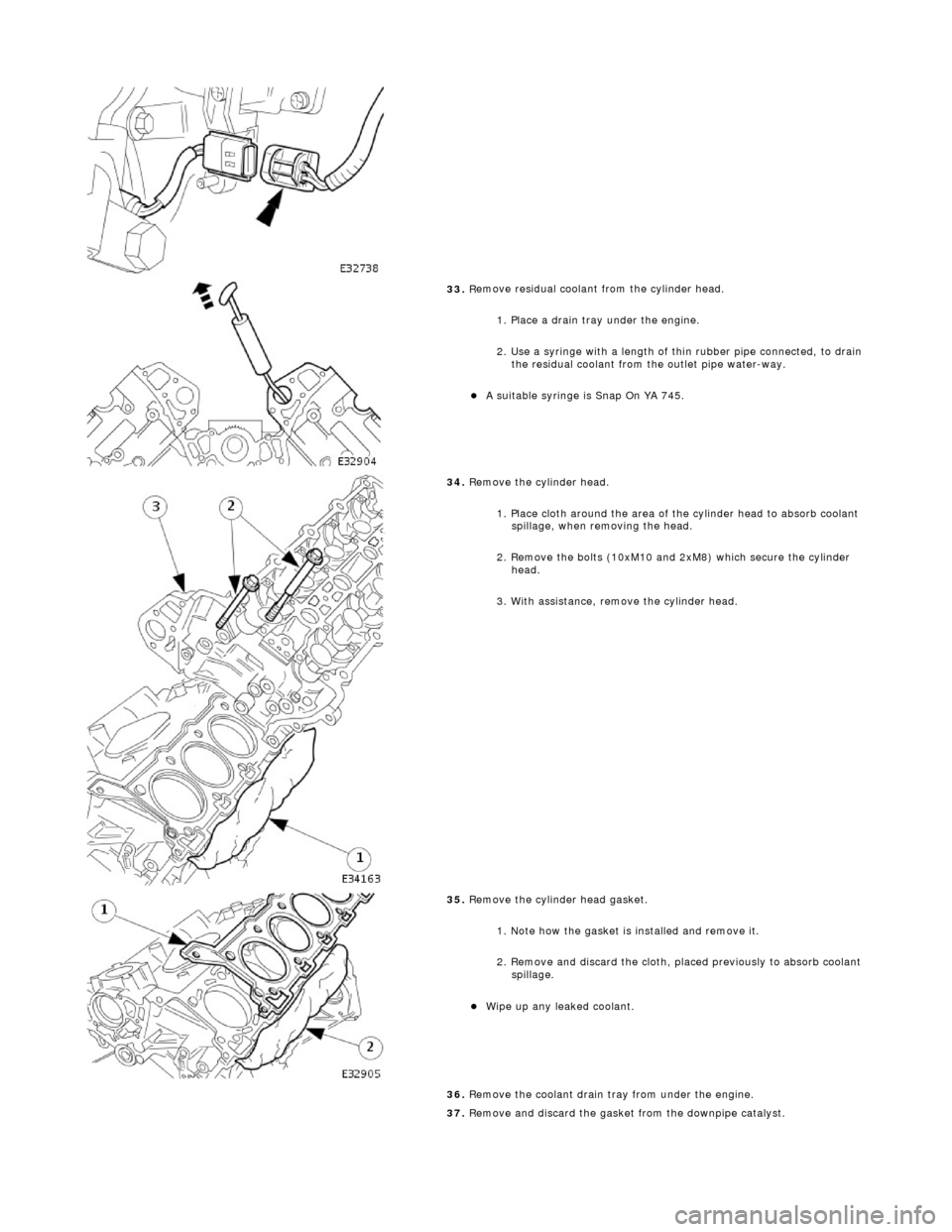
33. R
emove residual coolant from the cylinder head.
1. Place a drain tray under the engine.
2. Use a syringe with a length of thin rubber pipe connected, to drain the residual coolant from the outlet pipe water-way.
A s u
itable syringe is Snap On YA 745.
34 . R
emove the cylinder head.
1. Place cloth around the area of th e cylinder head to absorb coolant
spillage, when removing the head.
2. Remove the bolts (10xM10 and 2xM8) which secure the cylinder head.
3. With assistance, remove the cylinder head.
35 . R
emove the cylinder head gasket.
1. Note how the gasket is installed and remove it.
2. Remove and discard the cloth, placed previously to absorb coolant spillage.
Wipe up any l e
aked coolant.
36. Remove the coolant drain tray from under the engine.
37. Remove and discard the gasket from the downpipe catalyst.
Page 617 of 2490

Inst
allation
Cl
ean the gasket faces of the catalyst and the exhaust manifold.
38. Clean cylinder head and cylinder block gasket faces.
E
nsure that all threaded holes in the cylinder block face are clean and
free from oil.
Cl
ean and inspect the cylinder head bolts. They may be re-used on two
occasions. When re- used, each bolt head should be marked with one
dot from an automatic centre punch.
39. Clean and inspect all relevant components and mating faces.
1.
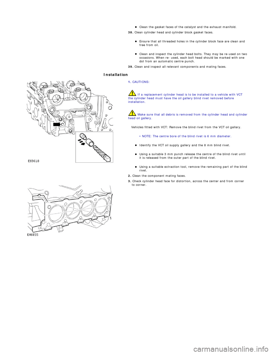
CAUTIONS:
If a replacement cylinder head is to be installed to a vehicle with VCT
the cylinder head must have the oil gallery blind rivet removed before
installation.
Make sure that all debris is removed from the cylinder head and cylinder
head oil gallery.
Vehicles fitted with VCT: Remove the blind rivet from the VCT oil gallary.
• NOTE: The centre bore of the blind rivet is 6 mm diameter.
I
dentify the VCT oil supply gallery and the 8 mm blind rivet.
U
sing a suitable 3 mm punch release the centre of the blind rivet until
it is released from the outer part of the blind rivet.
U
sing a suitable extraction tool, remo
ve the remaining part of the blind
rivet.
2.
Clean the component mating faces.
3.
Check cylinder head face for distortio
n, across the center and from corner
to corner.
Page 618 of 2490

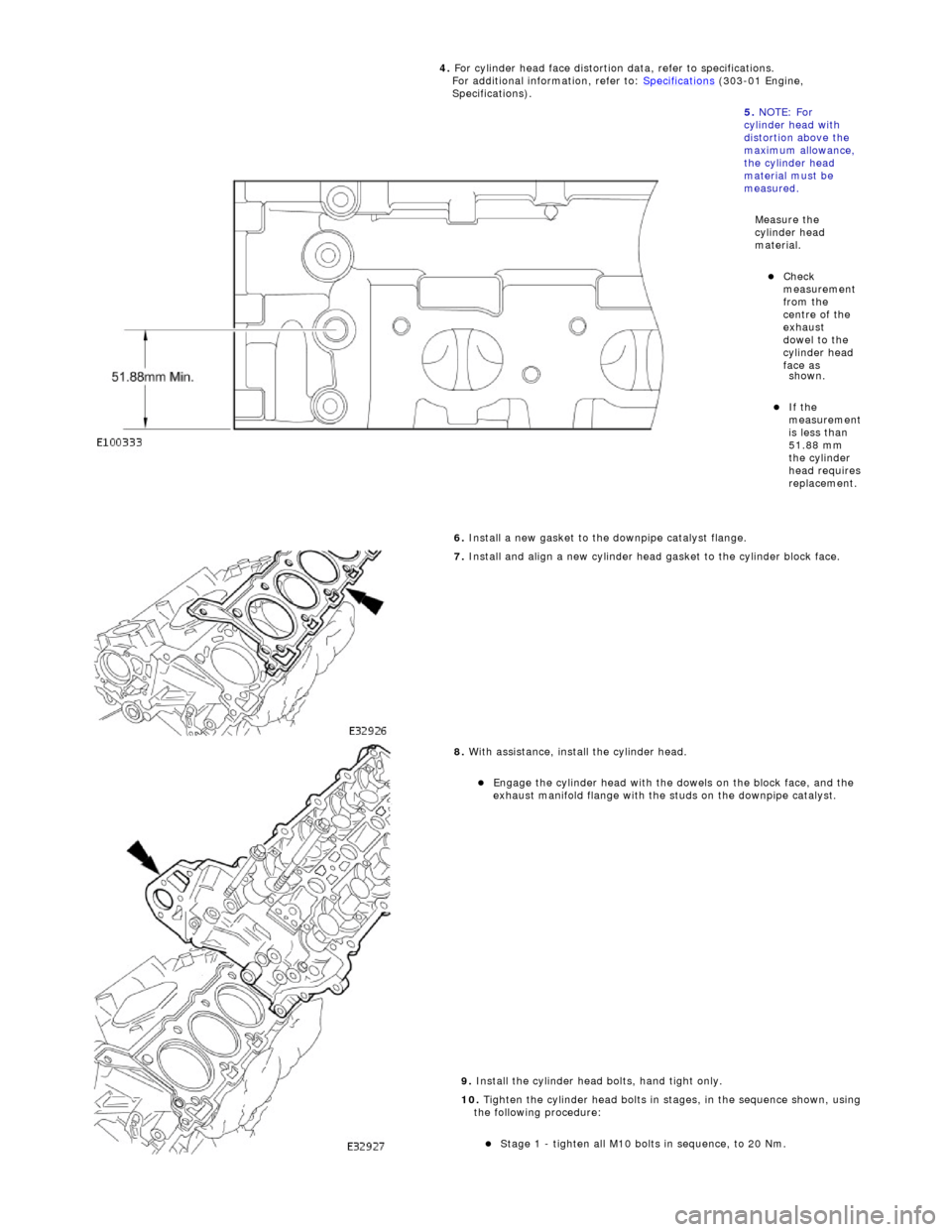
shown
.
If the
m
easurement
is less than
51.88 mm
the cylinder
head requires
replacement.
6.
Install a new gasket to the downpipe catalyst flange.
7.
Install and align a new cylinder head gasket to the cylinder block face.
8.
With assistance, install the cylinder head.
E
ngage t
he cylinder head with the dowels on the block face, and the
exhaust manifold flange with the studs on the downpipe catalyst.
9. Install the cylinder head bolts, hand tight only.
10. Tighten the cylinder head bolts in stages, in the sequence shown, using
the following procedure:
Stage 1 - ti
ghten all M10 bolt
s in sequence, to 20 Nm.
4.
For cylinder head face distortion
data, refer to specifications.
For additional information, refer to: Specifications
(303-01 Engi
ne,
Specifications).
5. NOTE: For
cylinder head with
distortion above the
maximum allowance,
the cylinder head
material must be
measured.
Measure the
cylinder head
material.
Che c
k
measurement
from the
centre of the
exhaust
dowel to the
cylinder head
face as
Page 632 of 2490

Installation
hea
d.
3. With assistance, remove the cylinder head.
34 . R
emove the cylinder head gasket.
1. Note how the gasket is installed and remove it.
2. Remove and discard the cloth, placed previously to absorb coolant spillage.
Wipe up any l e
aked coolant.
35. Remove the coolant drain tray from under the engine.
36. Remove and discard the gasket from the downpipe catalyst.
Cle
an the gasket faces of the catalyst and the exhaust manifold.
37. Clean cylinder head and cylinder block gasket faces.
Ensu
re that all threaded holes in the cylinder block face are clean and
free from oil.
Cl ean and
inspect the cylinder head bolts. They may be re-used on two
occasions. When re- used, each bolt head should be marked with one
dot from an automatic centre punch.
38. Clean and inspect all relevant components and mating faces.
1. CAUTIONS: If a replacement cylinder head is to be installed to a vehicle with VCT
the cylinder head must have the oil gallery blind rivet removed before
installation.
Make sure that all debris is removed from the cylinder head and cylinder
head oil gallery.
Vehicles fitted with VCT: Remove the blind rivet from the VCT oil gallary. • NOTE: The centre bore of the blind rivet is 6 mm diameter.
Page 633 of 2490

I
dentify the VCT oil supply gallery and the 8 mm blind rivet.
U
sing a suitable 3 mm punch release the centre of the blind rivet until
it is released from the outer part of the blind rivet.
U
sing a suitable extraction tool, remo
ve the remaining part of the blind
rivet.
2. Clean the component mating faces.
3.
Check cylinder head face for distortio
n, across the center and from corner
to corner.
4. For cylinder head face distortion data, refer to specifications.For additional
information, refer to: Specifications
(303
-00 Engine System - General
Information, Specifications).
5.
NOTE: For
cylinder head with
distortion above the
maximum allowance,
the cylinder head
material must be
measured.
Measure the
cylinder head
material.
Che
ck
measurement
from the
centre of the
exhaust
dowel to the
cylinder head
face as
shown.
If the
measurement
is less than
51.88 mm
the cylinder
head requires
replacement.
6.
Install a new gasket to the downpipe catalyst flange.
7. Install and align a new cylinder head gasket to the cylinder block face.
Page 682 of 2490

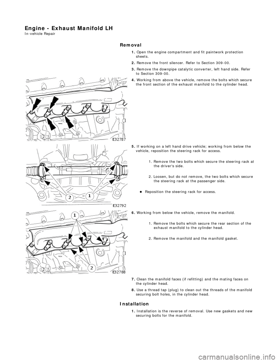
Engine - Exhaust Manifold LH
In-vehicle Repair
Removal
Installation
1.
Open the engine compartment and fit paintwork protection
sheets.
2. Remove the front silencer. Refer to Section 309-00.
3. Remove the downpipe catalytic converter, left hand side. Refer
to Section 309-00.
4. Working from above the vehicle, remove the bolts which secure
the front section of the exhaust manifold to the cylinder head.
5. If working on a left hand drive vehicle; working from below the
vehicle, reposition the steering rack for access.
1. Remove the two bolts which secure the steering rack at
the driver's side.
2. Loosen, but do not remove, the two bolts which secure the steering rack at the passenger side.
Reposition the steering rack for access.
6. Working from below the vehicle, remove the manifold.
1. Remove the bolts which secu re the rear section of the
exhaust manifold to the cylinder head.
2. Remove the manifold and the manifold gasket.
7. Clean the manifold faces (if refi tting) and the mating faces on
the cylinder head.
8. Use a thread tap (plug) to clean out the threads of the manifold
securing bolt holes, in the cylinder head.
1. Installation is the reverse of removal. Use new gaskets and new
securing bolts for the manifold.
Page 684 of 2490

Installation
9. Remove the manifold.
1. Remove the manifold and the manifold gasket from the cylinder head.
2. Remove the gasket from the EGR flange.
10. If fitting a new manifold, remove the two studs from the EGR
flange of the manifold. and transfer them to the new manifold.
11. Clean the manifold faces (if refi tting) and the mating faces on
the cylinder head.
12. Use a thread tap (plug) to clean out the threads of the
manifold securing bolt holes, in the cylinder head.
1. Fit a spacer to each new manifo ld securing bolt (8 bolts).
2. Fit the manifold and manifold gasket.
1. Fit and align the new gasket to the cylinder head.
2. Fit and align the manifo ld to the cylinder head.
3. Fit the rear four bolts wh ich secure the manifold, but
do not tighten.
3. Working from above the vehicle, fit and tighten the remaining
manifold securing bolts.
4. Working from below the vehicle, fu lly tighten the rear bolts on
each manifold.
5. Refit the steering rack (if removed for access).
1. Reposition th e steering rack.
2. Fit and tighten the rack mounting bolts on the passenger side.
Page 686 of 2490

Engine - Exhaust Manifold LH and RH
In-vehicle Repair
Removal
1. Open the engine compartment and fit paintwork protection
sheets.
2. Remove the downpipe catalytic converter, right hand side.
Refer to Section 309-00.
3. Remove the downpipe catalytic co nverter, left hand side. Refer
to Section 309-00.
4. Remove the front silencer. Refer to Section 309-00.
5. Remove the air cleaner assemb ly. Refer to Section 303-12.
6. Working from above the vehicl e, remove the bolts which
secure the front sectio n of the left hand exhaust manifold to
the cylinder head.
7. Working from below the vehicle, reposition the steering rack
for access.
1. Remove the two bolts which secure the steering rack at the driver's side.
2. Loosen, but do not remove, the two bolts which secure the steering rack at the passenger side.
Reposition the steering rack for access.
8. Working from below the vehicl e, remove the manifold.
1. Remove the bolts which secu re the rear section of the
exhaust manifold to the cylinder head.
2. Remove the manifold and the manifold gasket.
9. From above the vehicle, disconnect the EGR pipe from the
right hand exhaust manifold.
1. Remove the two nuts whic h secure the EGR flange to
the right hand exhaust manifold.
2. Reposition the EGR pipe from the manifold.
Page 687 of 2490

10. Remove the bolts which secure the front section of the right
hand exhaust manifold to the cylinder head.
11. Working from below the vehicle, remove the manifold bolts.
1. Remove the bolts which secu re the rear section of the
exhaust manifold to the cylinder head.
12. Remove the manifold.
1. Remove the manifold and the manifold gasket from the cylinder head.
2. Remove the gasket from the EGR flange.
13. If fitting a new manifold, remove the two studs from the EGR
flange of the manifold. and transfer them to the new manifold.
14. Clean the manifold faces (if refitting), the EGR pipe flange
and the mating faces on the cylinder head.
15. Use a thread tap (M8 x 1,25 plug) to clean out the threads of
each manifold securing bolt hole, in the cylinder heads.