hoses JAGUAR X308 1998 2.G Workshop Manual
[x] Cancel search | Manufacturer: JAGUAR, Model Year: 1998, Model line: X308, Model: JAGUAR X308 1998 2.GPages: 2490, PDF Size: 69.81 MB
Page 318 of 2490
Comp
onent Tests
Bra
k
e Booster
1.
1. Chec k all
hoses and connections. All unused vacuum connectors should be capped. Hoses and their connections
should be correctly secured and in good condition with no holes and no collapsed areas. Inspect the valve on the
brake booster for damage.
2. 2. Check the hydraulic brake system for leaks or low fluid.
3. 3. With the transmission in PARK, stop the engine and apply the parking brake. Pump the brake pedal several times
to exhaust all vacuum in the system.
4. 4. With the engine switched off and all vacuum in the system exhausted, appl y the brake pedal and hold it down.
Start the engine. If the vacuum system is operating, the brake pedal will tend to move downward under constant
foot pressure. If no motion is felt, the vacuum booster system is not functioning.
5. 5. Remove the vacuum hose from the brake booster. Manifold vacuum should be available at the brake booster end
of the hose with the engine at idle speed and the transm ission in PARK or NEUTRAL. Make sure that all unused
vacuum outlets are correctly capped, hose connectors are correctly secured and vacuum hoses are in good
condition. When it is established that manifold vacuum is available to the brake booster, connect the vacuum hose
to the brake booster and repeat Step 3. If no downward movement of the brake pedal is felt, install a new brake
booster.
6. 6. Operate the engine for a minimum of 10 seconds at a fast idle. Stop the engine and allow the vehicle to stand for
10 minutes. Then, apply th e brake pedal with approximately 89 N ( 20lb) of force. The pedal feel (brake
application) should be the same as that noted with the engine running. If the brake pedal feels hard (no power
assist), install a new valve and then re peat the test. If the brake pedal still feels hard, in stall a new brake booster.
If the brake pedal movement feels spongy, bleed the brak e system. For additional information, refer to General
Procedures in this section.
Bra k
e Master Cylinder
Usual
l
y, the first and strongest
indicator of anything wrong in the brake syst em is a feeling through the brake pedal. In
diagnosing the condition of the brake master cylinder, check pedal feel as evidence of a brake concern. Check for brake
warning lamp illumination and the brake fluid le vel in the brake master cylinder reservoir.
Normal Conditio
ns
The fo
llowing conditions are considered norm
al and are not indications that the brake master cylinder is in need of repair.
New bra
ke systems are designed to produc
e a pedal effort that is not as hard as in the past. Complaints of light
pedal efforts should be compared to the pedal effort s of another vehicle of the same model and year.
The fl
uid level will fall with brake pad wear.
Abnormal Conditions
•
NOTE: Prior to carrying out any diag
nosis, make sure the brake system warning indicator is functional.
Changes in the brake pedal feel or brake pedal travel are in dicators that something could be wrong in the brake system. The
diagnostic procedure and techniques use brake pedal feel, warning indicator illu mination and low brake fluid level as
indicators to diagnosing brake system co ncerns. The following conditions are cons idered abnormal and indicate that the
brake master cylinder is in need of repair:
Brake ped a
l goes down fast. Th
is could be caused by an ex ternal or internal leak.
Brake pedal goes down slowly
. This could be
caused by an internal or external leak.
Brak
e pedal is low or feels spongy. This condition may be ca
used by no fluid in the brake master cylinder, reservoir
Page 339 of 2490

Front Disc Brake -
Lubri
cants, Fluids, Sealants and Adhesives
Torques - Brembo Brakes
Torques
Brake Tube, Hoses and Bracket Torques
CAUTI
ON: Replacement of
nuts and bolts: Various thread-locking devices are used on nuts and bolts throughout the
vehicle. These devices restrict the number of times a nut or bolt can be used. See section 100-00 for information.
UnitS
pecification
Brake flu
id
ITT Supe
r Dot 4
Com
ponent
Nm
B
olt - anchor bracket to vertical link
18
0
Bo
lt - caliper to anchor bracket
DO
NOT REMOVE
Bleed n
ipple
12
-16
Hose u
nion to caliper
22
-26
Com
ponent
Nm
Bol
t - caliper carrier to vertical link
14
0
Guide
Pin - caliper housing to caliper carrier
25
-30
Com
ponent
Nm
Bleed n
ipple - front
4-
6
Bleed n
ipple - rear
8-1
1
Hose to fr
ont caliper
10
-14
Hose union to rear cal
iper - union bolt
30
-40
M1
0 hose locknut
15
-20
M10
brake tube female-nut
13
-17
M10
brake tube male-nut
13
-17
M12
brake tube male-nut
15
-20
M18
brake tube male-nut
22
-28
Brake tube clip retention
-bracket to body
4-
6
Page 341 of 2490
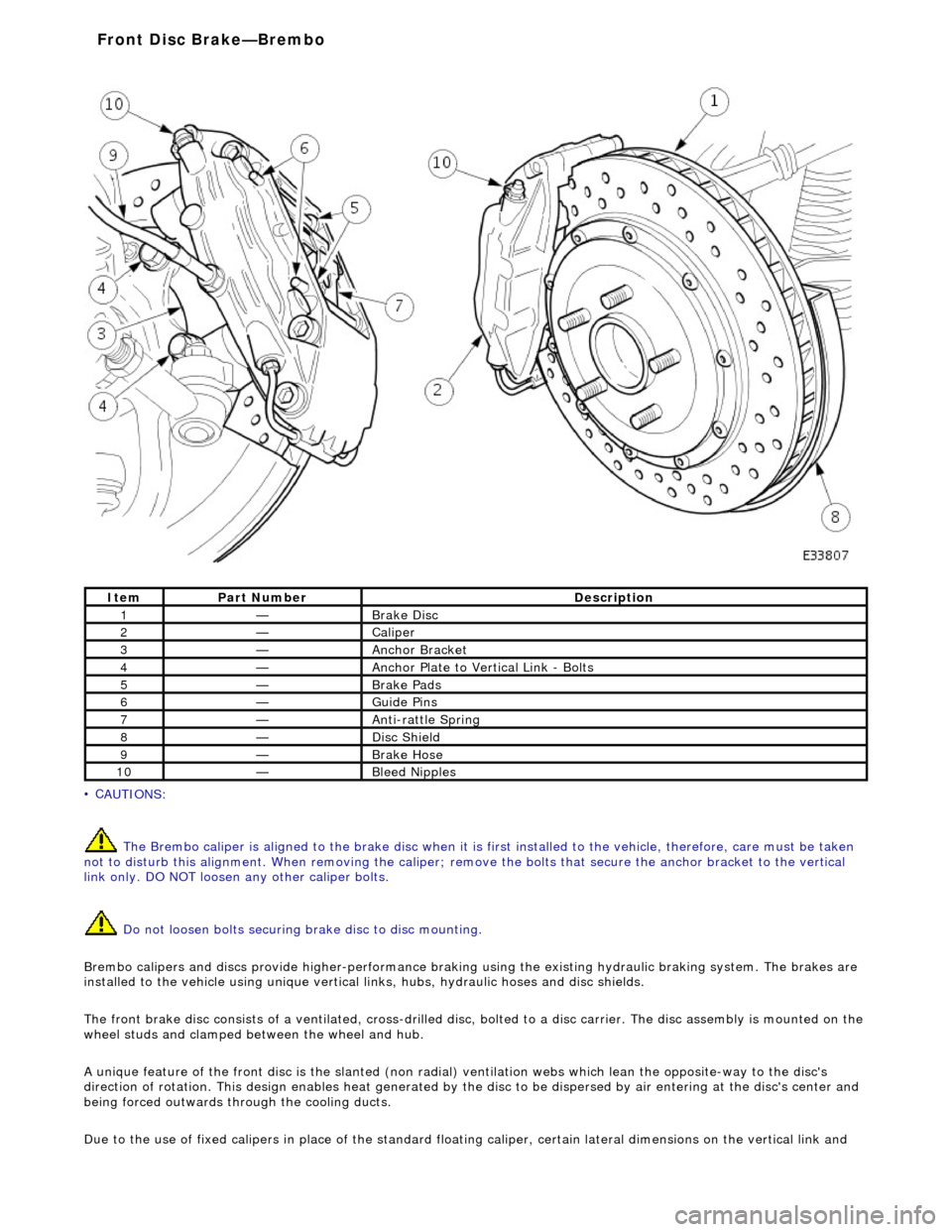
• C
AUTIONS:
The Brembo caliper is aligned to the brak e disc when it is first installed to the vehicle, therefore, care must be taken
not to disturb this alignment. When removi ng the caliper; remove the bolts that secure the anchor bracket to the vertical
link only. DO NOT loosen any other caliper bolts.
Do not loosen bolts securing brake disc to disc mounting.
Brembo calipers and discs provide higher -performance braking using the existing hydraulic braking system. The brakes are
installed to the vehicle using unique vertical links, hubs, hydraulic hoses and disc shields.
The front brake disc consists of a ventilated, cross-drilled disc, bolted to a disc carrier. The disc assemb ly is mounted on the
wheel studs and clamped be tween the wheel and hub.
A unique feature of the front disc is th e slanted (non radial) ventilation webs which lean the opposite-way to the disc's
direction of rotation. This design enables he at generated by the disc to be dispersed by air entering at the disc's center and
being forced outwards through the cooling ducts.
Due to the use of fixed calipers in place of the standard floating caliper, certain lateral dimensions on the vertical link and
It
em
Par
t Number
De
scription
1—B
rake Disc
2—Caliper
3—Anch
or Bracket
4—Anchor Pl
ate to Vertical Link - Bolts
5—Brake Pad
s
6—Guide P
ins
7—Anti-r
attle Spring
8—Di
sc Shield
9—Brake Hos
e
10—Bleed Nipp
les
Front Disc Brake—
Brembo
Page 342 of 2490
hub are critical to achieve correct clearan
ce and operation of
the brakes. Therefore special vertical links and hubs set within
a certain tolerance are inst alled with Brembo brakes.
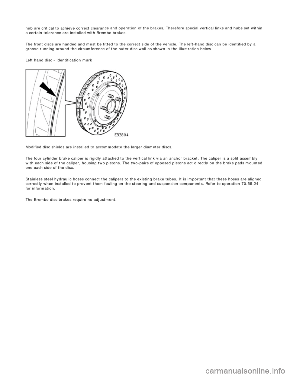
The front discs are handed and must be fitt ed to the correct side of the vehicle. The left-hand disc can be identified by a
groove running around the circumference of the outer disc wall as shown in the illustration below.
Left hand disc - identification mark
Modified disc shields are installed to accommodate the larger diameter discs.
The four cylinder brake caliper is rigidly attached to the vert ical link via an anchor bracket. The caliper is a split assembly
with each side of the caliper, housing two pistons. The two-pairs of opposed pistons act direct ly on the brake pads mounted
one each side of the disc.
Stainless steel hydraulic hoses connect the calipers to the existi ng brake tubes. It is important that these hoses are aligned
correctly when installed to pr event them fouling on the steering and suspen sion components. Refer to operation 70.55.24
for information.
The Brembo disc brakes require no adjustment.
Page 364 of 2490
Rear Disc Brake -
Lubric
ants, Fluids, Sealants and Adhesives
CAUTI
O
N: Do not use brake fluid ITT Supe
r Dot 4 on 2006my vehicles onwards. Fa ilure to follow this instruction may
result in damage to the vehicle.
• NOTE: Brake fluid ITT Super Dot 4 has now been superseded by Shell ESL Super Dot 4 which is the Jaguar recommended
brake fluid. Shell ESL Super Dot 4 can be used on all model years.
Torques
- Brembo Brakes
Torques
Brake Tube, Hoses and Bracket Torques
CAUTIO
N: Replacement of
nuts and bolts: Various thread-locking devices are used on nuts and bolts throughout the
vehicle. These devices restrict the number of times a nut or bolt can be used. See section 100-00 for information.
UnitS p
ecification
Brake flu
i
d
ITT Supe
r Dot 4
Brake flui
d
Shell E
SL Supe
r Dot 4
Brem
bo Brake G
rease
Mol
i
kote Cu 7439
Com
p
onent
Nm
Bol
t
- anchor bracket to hub carrier
60
B
o
lt - caliper to anchor bracket
DO
N
OT REMOVE
Bleed n
i
pple
12
-16
Un
ion bolt - brake hose to caliper
22
-26
Com p
onent
Nm
Bol
t
- caliper carrier to hub carrier
60
Guide
Pi
n - caliper housing to caliper carrier
25
-30
Comp
onent
Nm
Bleed ni
pple - front
4-6
Bleed ni
pple - rear
8-11
Hose union to rear cal
i
per - union bolt
30
-40
Hose to fr ont cal
iper
10
-14
M1 0 h
ose locknut
15
-20
M10 brake
tube female-nut
13
-17
M10 brake
tube male-nut
13
-17
M12 brake
tube male-nut
15
-20
M18 bu
lkhead brake tube connector
22
-28
Brake tube clip retention -
bracket to body
4-
6
Page 366 of 2490
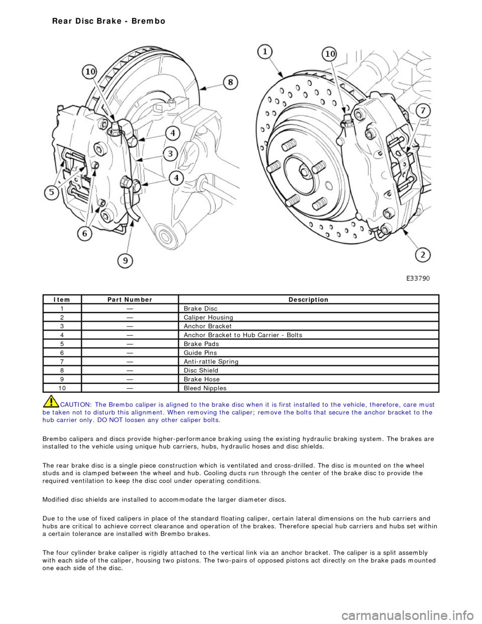
CAUTI O
N: The Brembo caliper is aligned to
the brake disc when it is first installed to the vehicle, therefore, care must
be taken not to disturb this alignment. When removing the ca liper; remove the bolts that secure the anchor bracket to the
hub carrier only. DO NOT loos en any other caliper bolts.
Brembo calipers and discs provide higher -performance braking using the existing hydraulic braking system. The brakes are
installed to the vehicle using unique hub carr iers, hubs, hydraulic hoses and disc shields.
The rear brake disc is a single piece co nstruction which is ventilated and cross-drilled. The disc is mounted on the wheel
studs and is clamped between the wheel and hub. Cooling ducts run through the ce nter of the brake disc to provide the
required ventilation to keep the disc cool under operating conditions.
Modified disc shields are installed to accommodate the larger diameter discs.
Due to the use of fixed calipers in place of the standard floating caliper, certain lateral dimensions on the hub carriers and
hubs are critical to achieve correct cleara nce and operation of the brakes. Therefore special hub carriers and hubs set within
a certain tolerance are inst alled with Brembo brakes.
The four cylinder brake caliper is rigidly attached to the vert ical link via an anchor bracket. The caliper is a split assembly
with each side of the caliper, housing two pistons. The two-pairs of opposed pistons act direct ly on the brake pads mounted
one each side of the disc.
It e
m
Par
t
Number
De
scr
iption
1—Brake D
i
sc
2—Caliper Housin
g
3—Anchor Bracke
t
4—Anchor Bracket to H
u
b Carrier - Bolts
5—Brake Pads
6—Guide Pi
ns
7—An
ti
-rattle Sprin
g
8—Di
sc
Shield
9—Brake Hos
e
10—Bleed Nipp
les
Rear Disc Brake - Brembo
Page 367 of 2490

Stai
nless steel hydraulic hoses connect the calipers to the existi
ng brake tubes. It is important that these hoses are aligned
correctly when installed to pr event them fouling on the steering and suspen sion components. Refer to operation 70.55.25
for information.
The Brembo disc brakes require no adjustment.
Page 405 of 2490

Hydraulic B
rake Actuation -
Lubri
cants, Fluids, Sealants and Adhesives
Torques
Torques - Brembo Brakes
Brake Tube, Hoses and Bracket Torques
CAUTI
ON: Replacement of
nuts and bolts: Various thread-locking devices are used on nuts and bolts throughout the
vehicle. These devices restrict the number of times a nut or bolt can be used. See section 100-00 for information.
UnitS
pecification
Brake flu
id
ITT Supe
r Dot 4
Com
ponent
Nm
N
ut - master cylinder to brake booster
21
-29
Nu
t - brake pedal pivot-pin to pedal housing
17
-23
Nu
t - brake switch to pedal housing
3
Nu
t - pedal housing to body
15
-20
Nu
t - brake booster to pedal housing
22
-28
Com
ponent
Nm
Bleed n
ipple
12
-16
U
nion bolt - brake hose to caliper
22
-26
Com
ponent
Nm
Bleed n
ipple - front
4-
6
Bleed n
ipple - rear
8-1
1
Hose to fr
ont caliper
10
-14
U
nion to rear caliper - union bolt
30
-40
M1
0 hose locknut
15
-20
M10
brake tube female-nut
13
-17
M10
brake tube male-nut
13
-17
M12
brake tube male-nut
15
-20
M18
brake tube male-nut
22
-28
Brake tube clip retention
-bracket to body
4-
6
Page 421 of 2490
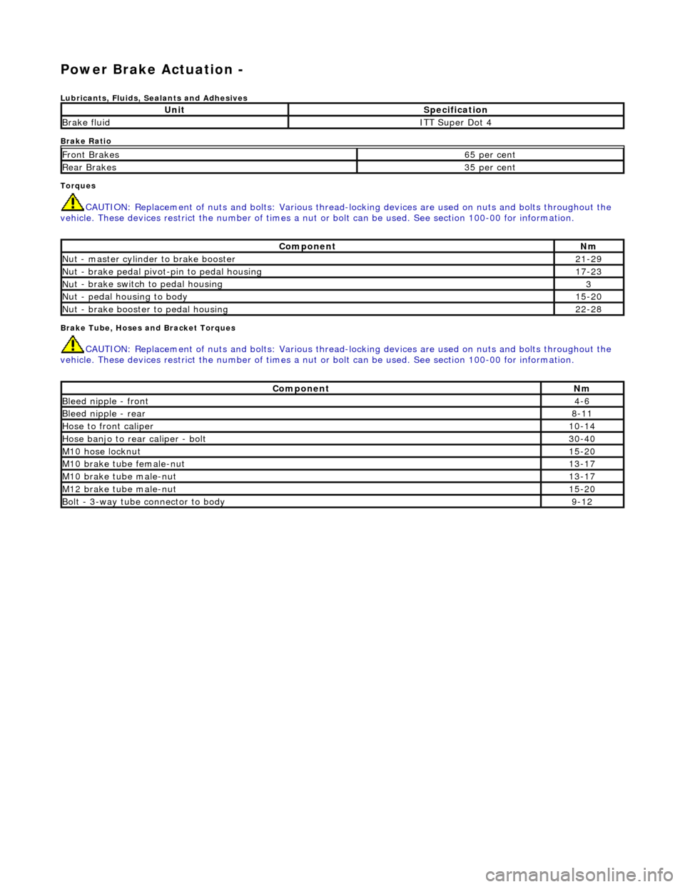
Power Brake Actuation -
Lubri
cants, Fluids, Sealants and Adhesives
Brake Ratio
Torques
CAUTI
ON: Replacement of
nuts and bolts: Various thread-locking devices are used on nuts and bolts throughout the
vehicle. These devices restrict the number of times a nut or bolt can be used. See section 100-00 for information.
B
rake Tube, Hoses and Bracket Torques
CAUTI
ON: Replacement of
nuts and bolts: Various thread-locking devices are used on nuts and bolts throughout the
vehicle. These devices restrict the number of times a nut or bolt can be used. See section 100-00 for information.
UnitS
pecification
Brake flu
id
ITT Supe
r Dot 4
Fr
ont Brakes
6
5 per cent
Rear B
rakes
3
5 per cent
Com
ponent
Nm
N
ut - master cylinder to brake booster
21
-29
Nu
t - brake pedal pivot-pin to pedal housing
17
-23
Nu
t - brake switch to pedal housing
3
Nu
t - pedal housing to body
15
-20
Nu
t - brake booster to pedal housing
22
-28
Com
ponent
Nm
Bleed n
ipple - front
4-
6
Bleed n
ipple - rear
8-
11
Hose to fr
ont caliper
10
-14
Hose banjo to rear caliper -
bolt
30
-40
M1
0 hose locknut
15
-20
M10
brake tube female-nut
13
-17
M10
brake tube male-nut
13
-17
M12
brake tube male-nut
15
-20
Bolt -
3-way tube connector to body
9-
12
Page 429 of 2490
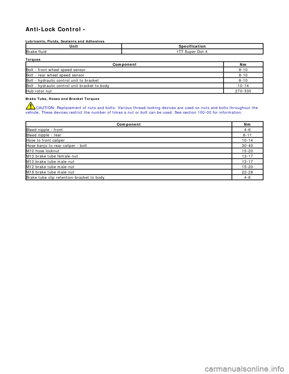
Anti-Lock Control -
Lubri
cants, Fluids, Sealants and Adhesives
Torques
Brake Tube, Hoses and Bracket Torques
CAUTI
ON: Replacement of
nuts and bolts: Various thread-locking devices are used on nuts and bolts throughout the
vehicle. These devices restrict the number of times a nut or bolt can be used. See section 100-00 for information.
UnitS
pecification
Brake flu
id
ITT Supe
r Dot 4
Com
ponent
Nm
Bol
t - front wheel speed sensor
8-
10
Bolt
- rear wheel speed sensor
8-
10
Bo
lt - hydraulic control unit to bracket
8-
10
Bolt -
hydraulic control unit bracket to body
10
-14
Hub rotor nut2
70-330
Com
ponent
Nm
Bleed n
ipple - front
4-
6
Bleed n
ipple - rear
8-1
1
Hose to fr
ont caliper
10
-14
Hose banjo to rear caliper -
bolt
30
-40
M1
0 hose locknut
15
-20
M10
brake tube female-nut
13
-17
M10
brake tube male-nut
13
-17
M12
brake tube male-nut
15
-20
M18
brake tube male-nut
22
-28
Brake tube clip retention
-bracket to body
4-
6