hoses JAGUAR X308 1998 2.G Owner's Guide
[x] Cancel search | Manufacturer: JAGUAR, Model Year: 1998, Model line: X308, Model: JAGUAR X308 1998 2.GPages: 2490, PDF Size: 69.81 MB
Page 903 of 2490
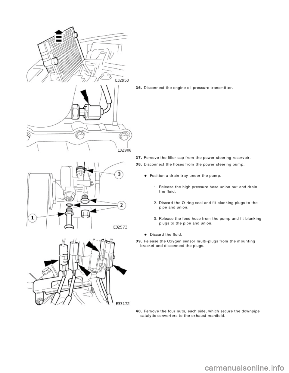
36. Disconnect the engine oi l pressure transmitter.
37. Remove the filler cap from the power steering reservoir.
38. Disconnect the hoses from the power steering pump.
Position a drain tray under the pump.
1. Release the high pressure hose union nut and drain the fluid.
2. Discard the O-ring seal an d fit blanking plugs to the
pipe and union.
3. Release the feed hose from the pump and fit blanking
plugs to the pipe and union.
Discard the fluid.
39. Release the Oxygen sensor multi-plugs from the mounting
bracket and disconnect the plugs.
40. Remove the four nuts, each side, which secure the downpipe
catalytic converters to the exhaust manifold.
Page 907 of 2490

56. Disconnect the fuel feed and return hoses.
1. Disconnect the fuel hoses at the Quick Fit connectors,
using special tool 310 - 044 for the feed hose and
310 - 54 for the return hose.
Disconnect the return hose from the feed hose clip.
Fit blanking plugs to the pipes.
57. Disconnect the pipes from the purge valve.
1. Remove the clip which secu res the part load breather
hose to the purge valve.
2. Disconnect the part load breather hose.
3. Disconnect the vacuum hose from the purge valve and reposition the hose.
58. Disconnect the throttle cable.
1. Secure the cable abutment to the bracket with tape or a ratchet strap, if nece ssary (to save subsequent
adjustment procedure). Remove the bolts which
secure the abutment bracke t to the throttle body.
2. Rotate the butterfly actuator cam and disconnect the cable. Reposition the cable.
59. Disconnect the heater and brake servo hoses.
1. Disconnect the he ater return hose.
2. Release the heater feed hose locking lever and
disconnect the hose.
Page 915 of 2490

Connect
the front muffler to
the intermediate muffler,
noting the alignment of the indicator rings.
W
ith the front muffler positioned correctly, tighten the
clamps (left-hand and right-hand sides) to the catalytic
converter.
21
.
Tighten the clamps (left-hand and right-hand sides),
intermediate mufflers to front muffler.
22
.
Tighten the downpipe bracket se curing bolts to the correct
torque
23
.
Connect the oil cooler pipes (w here fitted) to the engine.
1. Remove the blanking plugs from the pipes and from the mating unions on the engine.
2. Fit new O-ring seals to the pipes and lubricate with new engine oil.
3. Connect the pipes to the engine and fit the clamping
plate and bolt.
24. Lower the vehicle on the ramp.
25. Connect the heater and brake servo hoses.
1. Connect the heat er return hose.
2. Connect the heater feed hose and secure the locking
lever.
Page 917 of 2490
WARNING: B
EFORE PROCEEDING, IT IS ESSENTIAL THAT
THE WARNING NOTES GIVEN IN SECTION 100-00 (UNDER
THE HEADING 'SAFETY PRECAUTION S') ARE READ AND UNDERSTOOD.
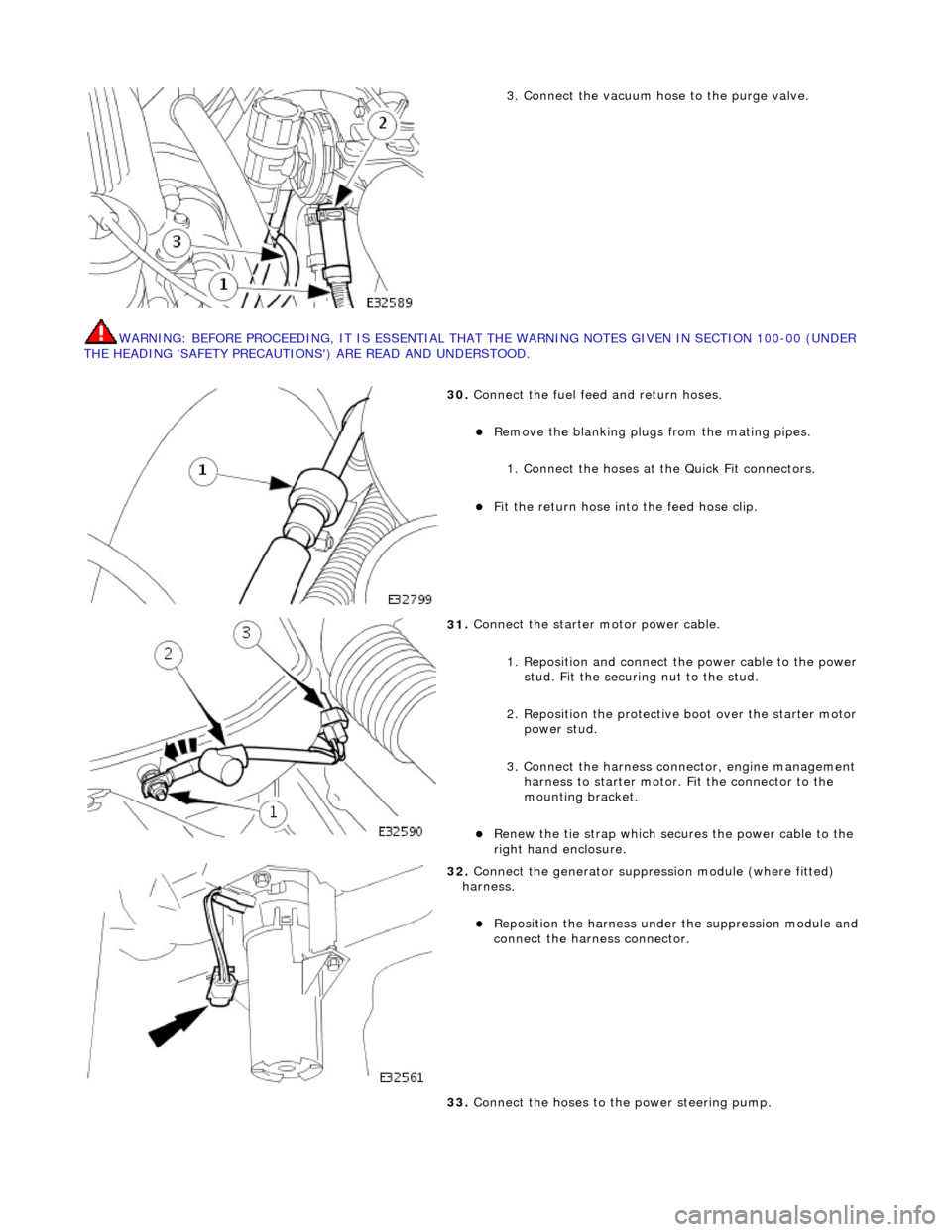
3.
Connect the vacuum hose to the purge valve.
30
.
Connect the fuel feed and return hoses.
R
emove the blanking plugs
from the mating pipes.
1. Connect the hoses at the Quick Fit connectors.
F
it the return hose into the feed hose clip.
31
.
Connect the starter motor power cable.
1. Reposition and connect the power cable to the power stud. Fit the securing nut to the stud.
2. Reposition the protective boot over the starter motor power stud.
3. Connect the harness connector, engine management harness to starter motor. Fit the connector to the
mounting bracket.
R
enew the tie strap which secures the power cable to the
right hand enclosure.
32
.
Connect the generator suppressi on module (where fitted)
harness.
Re
position the harn
ess under the suppression module and
connect the harness connector.
33. Connect the hoses to the power steering pump.
Page 921 of 2490
2
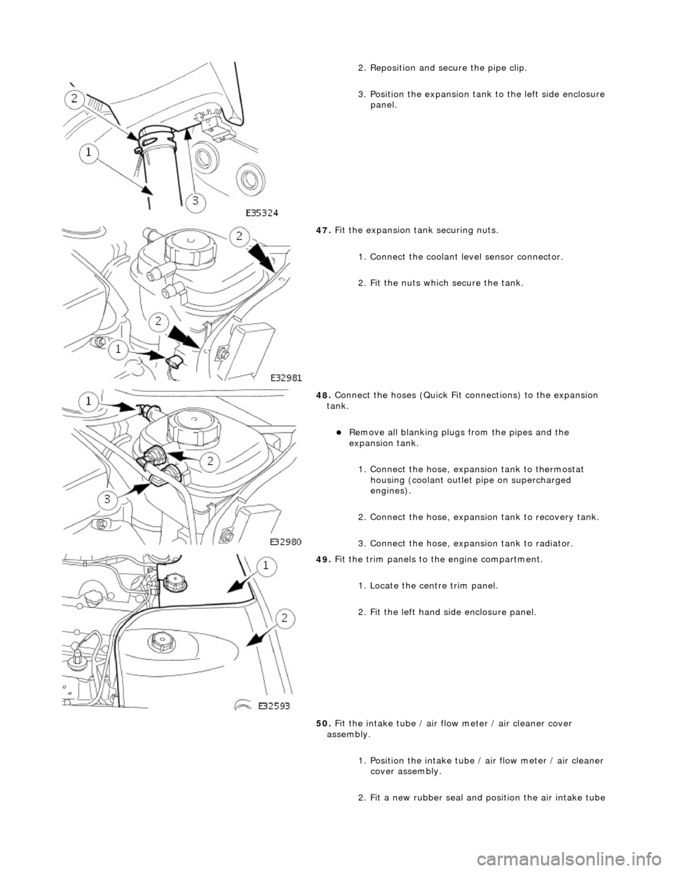
. Reposition and secure the pipe clip.
3. Position the expansion tank to the left side enclosure
panel.
47
.
Fit the expansion tank securing nuts.
1. Connect the coolant level sensor connector.
2. Fit the nuts which secure the tank.
48
.
Connect the hoses (Quick Fit connections) to the expansion
tank.
Remove all blanking plug s
from the pipes and the
expansion tank.
1. Connect the hose, expansion tank to thermostat housing (coolant outlet pipe on supercharged
engines).
2. Connect the hose, expansion tank to recovery tank.
3. Connect the hose, expansion tank to radiator.
49
.
Fit the trim panels to the engine compartment.
1. Locate the centre trim panel.
2. Fit the left hand side enclosure panel.
50. Fit the intake tube / air flow meter / air cleaner cover
assembly.
1. Position the intake tube / air flow meter / air cleaner
cover assembly.
2. Fit a new rubber seal and po sition the air intake tube
Page 929 of 2490

The cooling
pack incorporates the radiator a
ssembly with integral transmission oil cool er (located in the radiator outlet tank),
an air conditioning condenser, and the cooling fans and cowl assembly.
The cooling pack on supercharged vehicles is the same as described above, but with the addition of a charge air cooler
coolant radiator located in front of the condenser.
Radiator Mounti
ng/Retention
T
he radiator is mounted on four rubber mounts, one on each
end of the upper and lower horizontal face. The two lower
mountings are supported on two isolated brackets mounted on the body; the lower cradle assembly has subsequently been
deleted.
A closing panel made from polypropylene, which retains the radiat or assembly, fits over the top of the radiator and is bolted
to the vehicle top panel.
Coolant Hoses - Engine
Page 930 of 2490
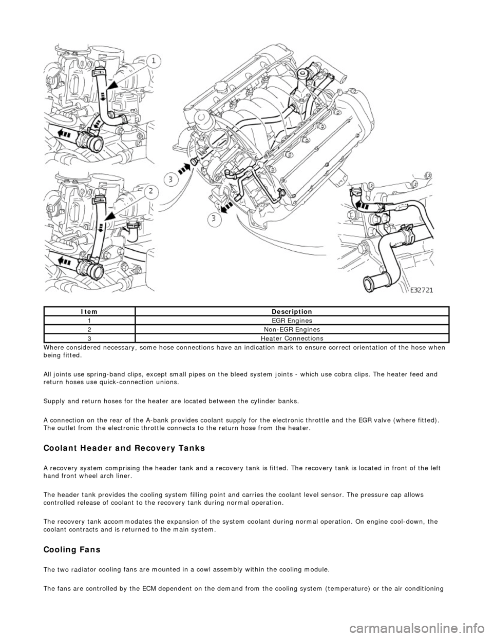
Whe r
e considered necessary, some hose conn
ections have an indication mark to ensure correct orientation of the hose when
being fitted.
All joints use spring-band clips, except small pipes on the bleed system joints - which use cobra clips. The heater feed and
return hoses use quick-connection unions.
Supply and return hoses for the heater are located between the cylinder banks.
A connection on the rear of the A-bank provides coolant supply for the electronic throttle and the EGR valve (where fitted).
The outlet from the electronic throttle connects to the return hose from the heater.
Cool
ant Header and Recovery Tanks
A recovery system comp
rising the header tank
and a recovery tank is fitted. The recove ry tank is located in front of the left
hand front wheel arch liner.
The header tank provides the cooling system filling point and carries the coolant level sensor. The pressure cap allows
controlled release of coolant to the re covery tank during normal operation.
The recovery tank accommodates the expansion of the system coolant during normal operation. On engine cool-down, the
coolant contracts and is returned to the main system.
Coo lin
g Fans
The two
rad
iator cooling fans are mounted in
a cowl assembly within the cooling module.
The fans are controlled by the ECM dependent on the demand fr om the cooling system (temperature) or the air conditioning
ItemDescrip
tion
1EGR
E
ngines
2Non
-
EGR Engines
3Hea
ter Connections
Page 963 of 2490

Engine Cooling - Coolant Expansi
on Tank
Re
moval and Installation
Remov
al
1.
O
pen the engine compartment and fit paintwork protection
sheets.
2. R
emove the centre trim panel
from the engine compartment.
1. Remove the left hand side enclosure panel.
2. Remove the centre trim panel.
3. Ensure that the cooling system is cool and very carefully,
remove the pressure cap.
4. Place a cloth under the expansion tank to absorb any spillage
caused by disconnecting the hoses.
5. R
elease the hoses (Quick Fit connections) from the expansion
tank.
1. Release the hose, expansion tank to thermostat housing (coolant outlet pipe on supercharged
engines).
2. Release the hose, expansion tank to recovery tank.
3. Release the hose, expansion tank to radiator..
6. Fit blanking plugs to the pipes and the tank.
7. Re
move the expansion tank from the mounting.
1. Disconnect the coolant level sensor connector.
2. Remove the nuts which secures the tank.
8. Remove the expansion tank from the vehicle.
1. Use a pipe clamp to clam p the bottom hose branch.
2. Release the pipe clip an d move it along the pipe.
3. Disconnect the tank from the bottom hose and
Page 965 of 2490

Engine Cooling - Coolant Outlet Pipe
Re
moval and Installation
Remov
al
Installation
1.
O
pen the engine compartment and fit paintwork protection
sheets.
2. Drain the radiator. Refer to Ge neral Procedures. Retain the
coolant drain tray in position to catch any spillage when
removing the outlet pipe.
3. Di
sconnect the hoses and multi-plug from the coolant outlet
pipe.
1. Release and reposition th e hose clip, and disconnect
the top hose.
2. Release and reposition th e hose clip, and disconnect
the heater hose.
3. Disconnect the multi-plug from the temperature sensor and unscrew the sens or from the outlet pipe.
4. Release and reposition the hose clip along the bypass
hose.
4. R
emove the coolant outlet pipe.
1. Remove the four bolts which secure the outlet pipe.
2. Remove the outlet pipe from the bypass hose and
from the cylinder heads.
5. Remove and discard the sealing rings from the outlet pipe
grooves.
1. Installation is the reverse of the remova l procedure. Use new
sealing rings on the coolant outlet pipe.
2. Tighten the coolant outlet pipe bolts to 10-14 Nm If replacing
the coolant temperature sensor, tighten to 15-19 Nm.
3. Refill the cooling system as de scribed in General Procedures.
Page 1043 of 2490
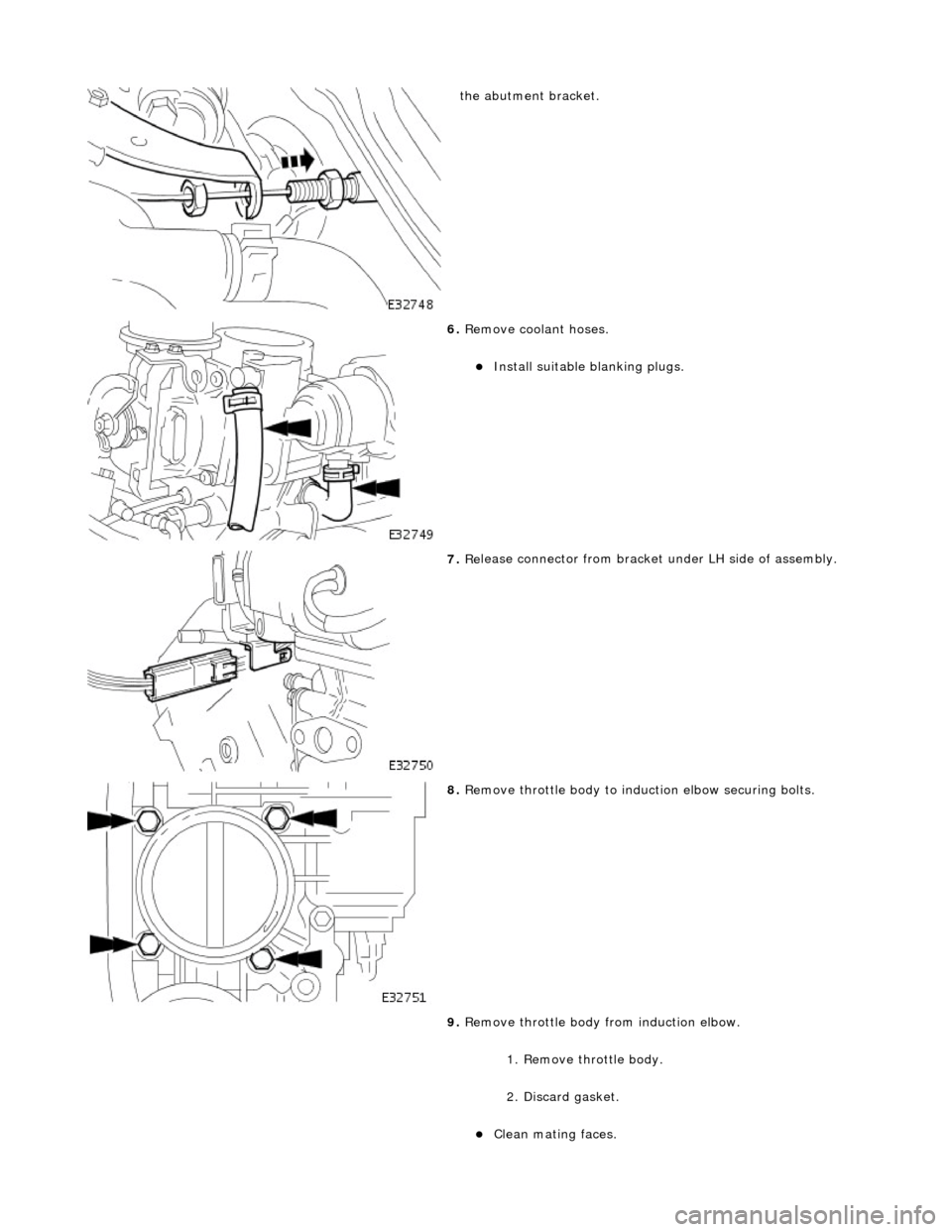
the
abutment bracket.
6. R
emove coolant hoses.
Inst
all suitable blanking plugs.
7. Re
lease connector from bracket
under LH side of assembly.
8. R
emove throttle body to indu
ction elbow securing bolts.
9. Remove throttle body from induction elbow.
1. Remove throttle body.
2. Discard gasket.
Cle
an mating faces.