muffler JAGUAR X308 1998 2.G Workshop Manual
[x] Cancel search | Manufacturer: JAGUAR, Model Year: 1998, Model line: X308, Model: JAGUAR X308 1998 2.GPages: 2490, PDF Size: 69.81 MB
Page 19 of 2490

В В В В В В В В 309:В ExhaustВ Syst
em
В
В
В В В В В В В В В В В В 309‐00: В ExhaustВ SystemВ
В В В В В В В В В В В В В В В В Specification В
В В В В В В В В В В В В В В В В Description В and В Operation В
В В В В В В В В В В В В В В В В В В В В ExhaustВ System В
В В В В В В В В В В В В В В В В Diagnosis В and В Testing В
В В В В В В В В В В В В В В В В В В В В ExhaustВ System В
В В В В В В В В В В В В В В В В RemovalВ and В Installation В
В В В В В В В В В В В В В В В В В В В В CatalyticВ Converter В LHВ (17.50.15)  ‐ 3.2L В NA В V8  ‐ AJ26/4.0LВ NAВ V8  ‐ AJ27 В
В В В В В В В В В В В В В В В В В В В В CatalyticВ Converter В LHВ (17.50.15)  ‐ 4.0L В SCВ V8 ‐ AJ26, В Vehicles В With:В В
В В В В В В В В В В Supercharger В
В В В В В В В В В В В В В В В В В В В В CatalyticВ Converter В RH В (17.50.16)  ‐ 3.2L В NA В V8  ‐ AJ26/4.0LВ NAВ V8  ‐ AJ27 В
В В В В В В В В В В В В В В В В В В В В Catalyt
icВ Converter В RH В (17.50.16)  ‐ 4.0L В SCВ V8 ‐ AJ26, В Vehicles В With:В В
В В В В В В В В В В Supercharger В
В В В В В В В В В В В В В В В В В В В В CatalyticВ Converter В Gasket В LHВ (17.50.06)  ‐ 3.2L В NA В V8  ‐ AJ26/4.0L В NA В V8  ‐ AJ27 В
В В В В В В В В В В В В В В В В В В В В CatalyticВ Converter В Gasket В LHВ (17.50.06)  ‐ 4.0L В SCВ V8 ‐ AJ26 В
В В В В В В В В В В В В В В В В В В В В CatalyticВ Converter В Gasket В RH В (17.50.07)  ‐ 3.2L В NAВ V8  ‐ AJ26/4.0L В NA В V8  ‐ AJ27 В
В В В В В В В В В В В В В В В В В В В В Catalyt
icВ Converter В Gasket В RH В (17.50.07)  ‐ 4.0L В SCВ V8 ‐ AJ26 В
В В В В В В В В В В В В В В В В В В В В FrontВ Muffler В (30.10.18)  ‐ 3.2L В NA В V8  ‐ AJ26/4.0LВ NAВ V8  ‐ AJ27 В
В В В В В В В В В В В В В В В В В В В В FrontВ Muffler В (30.10.18)  ‐ 4.0L В SCВ V8 ‐ AJ26 В
В В В В В В В В В В В В В В В В В В В В IntermediateВ MufflerВ LHВ (30.10.15)  ‐ 3.2L В NA В V8  ‐ AJ26/4.0L В NA В V8  ‐ AJ27 В
                    Intermediate Muffler LH (30.10.15)  ‐ 4.0L  SC V8 ‐ AJ
26 В
В В В В В В В В В В В В В В В В В В В В IntermediateВ MufflerВ RH В (30.10.16)  ‐ 3.2L В NA В V8  ‐ AJ26/4.0L В NA В V8  ‐ AJ27 В
В В В В В В В В В В В В В В В В В В В В IntermediateВ MufflerВ RH В (30.10.16)  ‐ 4.0L В SCВ V8 ‐ AJ26 В
В В В В В В В В В В В В В В В В В В В В MufflerВ andВ TailpipeВ LHВ (30.10.22) В
В В В В В В В В В В В В В В В В В В В В MufflerВ andВ TailpipeВ RHВ (30.10.52) В
В
В В В В В В В В 310: В Fuel В System В
В
В В В В В В В В В В В В 310‐00: В Fuel В System  ‐ General В Information В
В В В В В В В В В В В В В В В В GeneralВ Procedures В
В В В В В В В В В В В В В В В В В В В В FuelВ System В Pressure В Check В
В В В В В В В В В В В В В В В В В В В В FuelВ Tank В Draining В
В
В В
Fuel В Sy stem В Pres
sure
В Release В
Page 282 of 2490

Driveshaft - Driveshaft
Remo
val and Installation
Remov
a
l
CAUTI
O
N: To preserve 'drive line' refine
ment, individual parts, other than fixings, MUST NOT be renewed. In the event
of any balance or driveshaft component related problem, the complete assembly must be renewed. Under no circumstances
may the flexible (Jurid) coupling be remo ved from the driveshaft (or its fixings be loosened). Do not drop or subject the
driveshaft to damage.
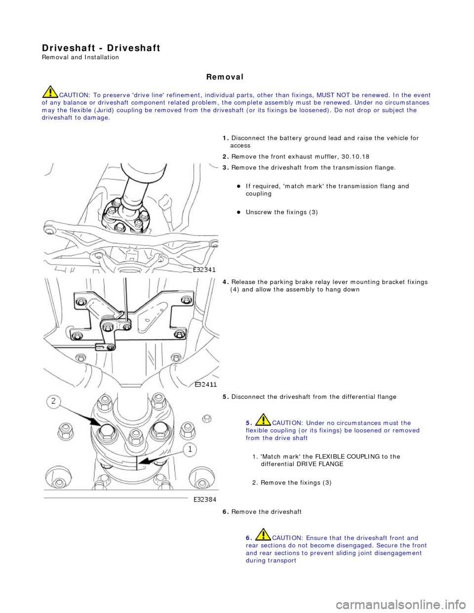
1. Disc
onnect the battery ground
lead and raise the vehicle for
access
2. Remove the front exha ust muffler, 30.10.18
3. Re
move the driveshaft from
the transmission flange.
пЃ¬If required, 'match mark'
the transmissi on flang and
coupling
пЃ¬Unscrew the fi xings (3)
4. Relea s
e the parking brake relay
lever mounting bracket fixings
(4) and allow the assembly to hang down
5. Disc onne
ct the driveshaft fr
om the differential flange
5. CAUTION: Under no circumstances must the
flexible coupling (or its fixings) be loosened or removed
from the drive shaft
1. 'Match mark' the FLEX IBLE COUPLING to the
differential DRIVE FLANGE
2. Remove the fixings (3)
6. Re
move the driveshaft
6. CAUTION: Ensure that the driveshaft front and
rear sections do not become disengaged. Secure the front
and rear sections to preven t sliding joint disengagement
during transport
Page 696 of 2490

Engine - Flexplate4.0L NA V8 - AJ27/3.2L NA V8 - AJ26
In-vehicle Repair
Removal
Installation
1. Open the engine compartment and fit paint protection sheets.
2. Disconnect the batt ery ground cable.
пЃ¬Remove the battery cover.
3. Remove the Engine Covers, Air Intake Tube, Catalytic
Converters and the Front Muffler. Drain the transmission fluid
and remove the transmission for access.
пЃ¬Refer to Operation 44.20. 01 Transmission Remove, in
Section 307-01A, which includes each of the above
operations.
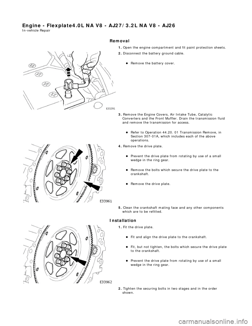
4. Remove the drive plate.
пЃ¬Prevent the drive plate from rotating by use of a small
wedge in the ring gear.
пЃ¬Remove the bolts which secure the drive plate to the
crankshaft.
пЃ¬Remove the drive plate.
5. Clean the crankshaft mating face and any other components
which are to be refitted.
1. Fit the drive plate.
пЃ¬Fit and align the drive plate to the crankshaft.
пЃ¬Fit, but not tighten, the bolt s which secure the drive plate
to the crankshaft.
пЃ¬Prevent the drive plate from rotating by use of a small
wedge in the ring gear.
2. Tighten the securing bolts in two stages and in the order
shown.
Page 697 of 2490

пЃ¬STAGE ONE tighten to 14 - 16 Nm.
3. Tighten the securing bolts in two stages and in the order
shown.
пЃ¬STAGE TWO tighten to 95 - 125 Nm.
4. Refit the Transmission, Catalytic Converters and the Front
Muffler, Air Intake Tube an d Engine Covers. Refill the
transmission with new fluid.
пЃ¬Refer to Operation 44.20. 01 Transmission Install, in
Section 307-01A, which includes each of the above
operations.
5. Remove the paint protection sheets and close the engine
compartment cover.
6. Connect the battery and fit the battery cover.
пЃ¬Refer to the Battery Reconnection Procedure 86.15.15.
Page 698 of 2490

Engine - Flexplate4.0L SC V8 - AJ26
In-vehicle Repair
Removal
Installation
1. Open the engine compartment and fit paint protection sheets.
2. Disconnect the batt ery ground cable.
пЃ¬Remove the battery cover.
3. Remove the Engine Covers, Air Intake Tube, Catalytic
Converters and the Front Muffler. Drain the transmission fluid
and remove the transmission for access.
пЃ¬Refer to Operation 44.20. 01 Transmission Remove, in
Section 307-01B, which includes each of the above
operations.
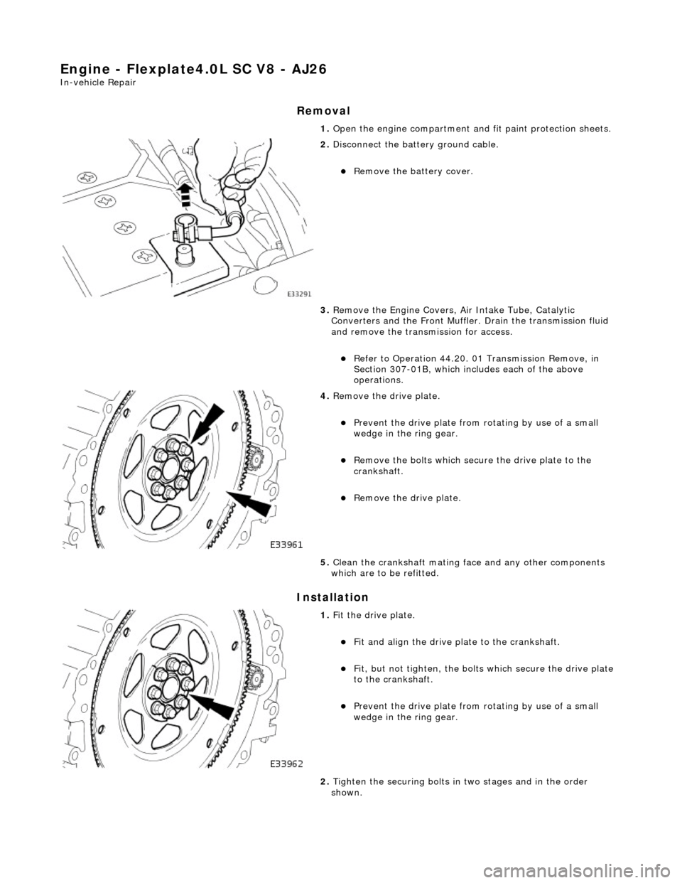
4. Remove the drive plate.
пЃ¬Prevent the drive plate from rotating by use of a small
wedge in the ring gear.
пЃ¬Remove the bolts which secure the drive plate to the
crankshaft.
пЃ¬Remove the drive plate.
5. Clean the crankshaft mating face and any other components
which are to be refitted.
1. Fit the drive plate.
пЃ¬Fit and align the drive plate to the crankshaft.
пЃ¬Fit, but not tighten, the bolt s which secure the drive plate
to the crankshaft.
пЃ¬Prevent the drive plate from rotating by use of a small
wedge in the ring gear.
2. Tighten the securing bolts in two stages and in the order
shown.
Page 699 of 2490

пЃ¬STAGE ONE tighten to 14 - 16 Nm.
3. Tighten the securing bolts in two stages and in the order
shown.
пЃ¬STAGE TWO tighten to 95 - 125 Nm.
4. Refit the Transmission, Catalytic Converters and the Front
Muffler, Air Intake Tube an d Engine Covers. Refill the
transmission with new fluid.
пЃ¬Refer to Operation 44.20. 01 Transmission Install, in
Section 307-01B, which includes each of the above
operations.
5. Remove the paint protection sheets and close the engine
compartment cover.
6. Connect the battery and fit the battery cover.
пЃ¬Refer to the Battery Reconnection Procedure 86.15.15.
Page 904 of 2490

41. Raise the vehicle on the ramp.
42. Drain the engine oil.
1. Position the waste oil bowser.
2. Remove the sump drain pl ug and drain the engine oil.
пЃ¬Wipe the drain plug and refit it to the sump to prevent oil
dripping.
пЃ¬Move the oil bowser away from the vehicle.
43. Move the front muffler forwar d to allow the intermediate
mufflers to be displaced.
пЃ¬Slacken the clamps (left-hand and right-hand sides),
catalytic converter to front muffler.
44. Slacken the clamps (left-han d and right-hand sides),
intermediate mufflers to front muffler.
45. Remove the front muffler.
пЃ¬Disconnect the front muffler from the intermediate
mufflers and then from the downpipe catalytic converters.
46. Remove the downpipe catalytic converters.
Page 914 of 2490

пЃ¬Repeat
the above procedure for the other side.
16 . Connect
the driveshaft (propshaft
) flange to the transmission
output flange.
пЃ¬F i
t the three bolts which secure the flange.
17 . F
it the downpipe catalytic converters.
1. Fit a new gasket to the downpipe flange and fit the
downpipe assembly. to the manifold.
пЃ¬F i
t the bolts which secure
the downpipe to the lower
mounting bracket.
пЃ¬Repeat the above operation
s
for the other downpipe
catalytic converter.
18 . F
rom above the vehicle, tighte
n the manifold flange nuts, A-
Bank and B-Bank flanges, to the correct torque.
19. Fit the front muffler assembly.
пЃ¬Locate the front muf fler into the
downpipe catalytic
converters.
20. Move the front muffler forwar d to allow the intermediate
mufflers to be connected.
Page 915 of 2490

пЃ¬Connect
the front muffler to
the intermediate muffler,
noting the alignment of the indicator rings.
пЃ¬W
ith the front muffler positioned correctly, tighten the
clamps (left-hand and right-hand sides) to the catalytic
converter.
21
.
Tighten the clamps (left-hand and right-hand sides),
intermediate mufflers to front muffler.
22
.
Tighten the downpipe bracket se curing bolts to the correct
torque
23
.
Connect the oil cooler pipes (w here fitted) to the engine.
1. Remove the blanking plugs from the pipes and from the mating unions on the engine.
2. Fit new O-ring seals to the pipes and lubricate with new engine oil.
3. Connect the pipes to the engine and fit the clamping
plate and bolt.
24. Lower the vehicle on the ramp.
25. Connect the heater and brake servo hoses.
1. Connect the heat er return hose.
2. Connect the heater feed hose and secure the locking
lever.
Page 1249 of 2490

Electron
ic Engine Controls -
Heated Oxygen Sensor (HO2S) LH
Rem
oval and Installation
General Equipment
Remov
al
Installation
Snap
-on tool S6176
1. WARNING: ENSURE THAT TH E EXHAUST AND CATALYST
ARE COLD BEFORE COMMENCING WORK
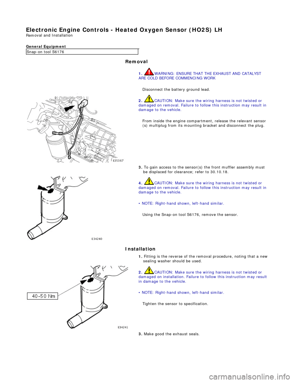
Disconnect the battery ground lead.
2.
CAUTION: Make sure the wiring harness is not twisted or
damaged on removal. Failure to follow this instruction may result in
damage to the vehicle.
From inside the engine compartm ent, release the relevant sensor
(s) multiplug from its mounting bracket and disconnect the plug.
3.
To gain access to the sensor(s) the front muffler assembly must
be displaced for clearance; refer to 30.10.18.
4.
CAUTION: Make sure the wiring harness is not twisted or
damaged on removal. Failure to follow this instruction may result in
damage to the vehicle.
• NOTE: Right-hand shown, left-hand similar.
Using the Snap-on tool S6176, remove the sensor.
1.
Fitting is the reverse of the remo val procedure, noting that a new
sealing washer should be used.
2.
CAUTION: Make sure the wiring harness is not twisted or
damaged on installation. Failure to follow this instruction may result
in damage to the vehicle.
• NOTE: Right-hand shown, left-hand similar.
Tighten the sensor to specification.
3.
Make good the exhaust seals.