JAGUAR X308 1998 2.G Owner's Manual
X308 1998 2.G
JAGUAR
JAGUAR
https://www.carmanualsonline.info/img/21/7640/w960_7640-0.png
JAGUAR X308 1998 2.G Owner's Manual
Page 1522 of 2490
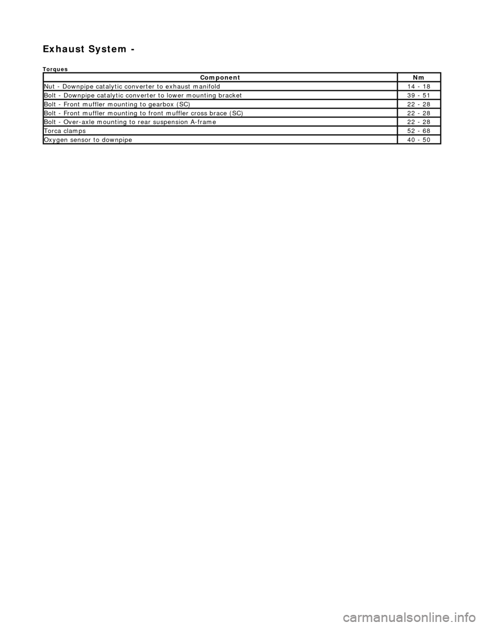
Exhaust System -
Torques
ComponentNm
Nut - Downpipe catalytic converter to exhaust manifold14 - 18
Bolt - Downpipe catalytic converter to lower mounting bracket39 - 51
Bolt - Front muffler mounting to gearbox (SC)22 - 28
Bolt - Front muffler mounting to front muffler cross brace (SC)22 - 28
Bolt - Over-axle mounting to rear suspension A-frame22 - 28
Torca clamps52 - 68
Oxygen sensor to downpipe40 - 50
Page 1524 of 2490
All vehicles are fitted with a stainless steel exhaust system which features:
пЃ¬Low back-pressure gas flow. пЃ¬Catalytic converters for mark ets having unleaded fuel. пЃ¬Front muffler common to the left-hand and right-hand engine cylinder banks.
Downpipe Catalytic Converter Assembly
Page 1525 of 2490
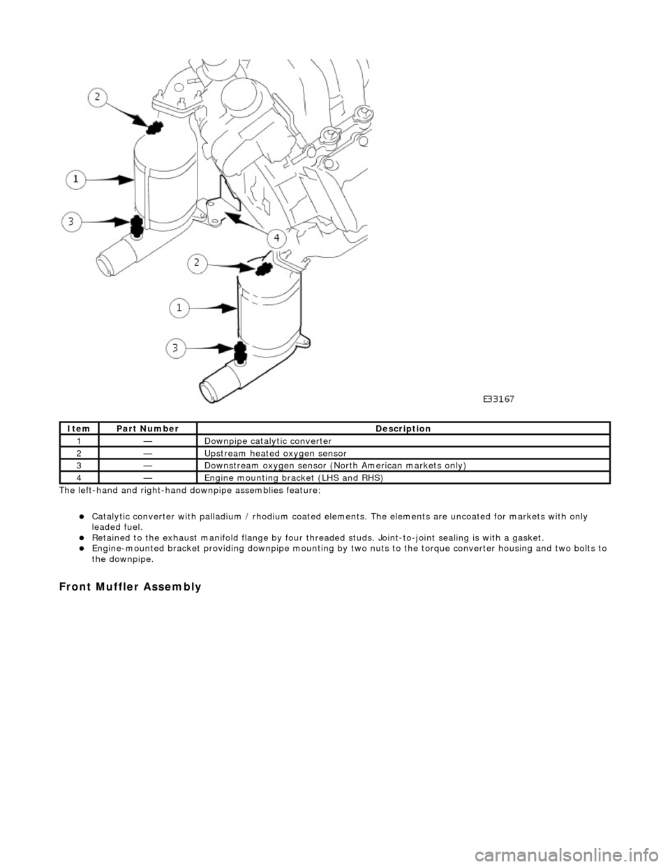
The left-hand and right-hand do wnpipe assemblies feature:
пЃ¬Catalytic converter with palladium / rhodium coated elem ents. The elements are uncoated for markets with only
leaded fuel.
пЃ¬Retained to the exhaust manifold flange by four thread ed studs. Joint-to-joint sealing is with a gasket. пЃ¬Engine-mounted bracket providing downpipe mounting by two nuts to the torque converter housing and two bolts to
the downpipe.
Front Muffler Assembly
ItemPart NumberDescription
1—Downpipe catalytic converter
2—Upstream heated oxygen sensor
3—Downstream oxygen sensor (North American markets only)
4—Engine mounting bracket (LHS and RHS)
Page 1526 of 2490
The front muffler assembly features:
пЃ¬Twin-pipe absorption type muffler. пЃ¬Pipe-to-pipe pres sure damping. пЃ¬Inlet and outlet pipes welded to the muffler. пЃ¬Front joints are flanged on supercharged engines and a flexible pipe (not removable separately ) is fitted behind each
flange - refer to the inset above.
Intermediate Muffler Assembly
The left- and right-hand intermedia te muffler assemblies comprise:
пЃ¬Absorption type muffler. пЃ¬Inlet and outlet pipes welded to the muffler.
Page 1527 of 2490
Rear Muffler Assembly
The left-hand and right-hand rear muffler assemblies comprise:
пЃ¬Absorption type muffler. пЃ¬Inlet pipe and tailpipe welded to the muffler. пЃ¬Tailpipe bright finisher integral with the tailpipe.
Tailpipe Clearance to Moulded Bumper
Page 1638 of 2490
Exha
ust System - Catalyti
c Converter LH4.0L NA V8 - AJ27/3.2L NA V8 -
AJ26
Re mo
val and Installation
Remova
l
1.
Op
en the engine compartment and fit paintwork protection
sheets.
2. Remove the front muffler; refer to Operation 30.10.18 in this
section.
3. Re
move the centre trim panel
from the engine compartment.
1. Remove the left hand side enclosure panel.
2. Remove the centre trim panel.
4. Repo
sition the expansion tank from the mounting.
1. Disconnect the coolant level sensor connector.
2. Remove the nuts which secures the tank.
5. CAUT
ION: Note the position of the upstream and
downstream (where fitted) o xygen sensor multiplugs for
reassembly.
Disconnect the oxygen sensor multiplugs.
пЃ¬Di spl
ace the multiplugs from the engine mounting bracket.
пЃ¬Dis
connect the plug(s) from the oxygen sensor(s)
6.
Re
move the four nuts which se
cure the downpipe catalytic
converter to the exhaust manifold.
Page 1641 of 2490
2.
Connect the harness connector
8. R
efit the centre trim panel and th
e left hand enclosure panel to
the engine compartment.
1. Refit the centre trim panel.
2. Refit the left hand enclosure panel.
9. Raise the ramp.
10
.
Tighten the mounting brac ket securing bolts.
11. Fit the front muffler; refer to Operation 30.10.18.
12. Lower the ramp.
13. Remove the paintwork protection sheets and close the engine
cover.
Page 1643 of 2490
6. R
aise the vehicle on a ramp.
7. R
emove the bolts which secure
the rear of the front muffler
assembly to the transmission rear mounting.
8. R
emove the bolts which secure
the front flange of the front
muffler to the downpipe flange.
пЃ¬R
epeat for the flange bolt
s on the opposite side.
9. R
emove the gasket from the front
muffler flange at each side.
пЃ¬R
eposition the front silencer rearwards.
пЃ¬R
emove the gasket from each flange.
10
.
Remove the downpipe catalytic converter.
пЃ¬R
emove the bolts which se
cure the downpipe lower
mounting bracket.
пЃ¬Remove the
downpipe assembly.
11. Remove the oxygen sensor(s).
пЃ¬The downstream sensor i
s fitt
ed only for North American
markets.
Page 1646 of 2490
11
. Connect
the downpipe cataly
tic converter to the front
muffler.
1. Position a new gasket to the flange studs at each side.
2. Connect the the front mu ffler assembly to each
downpipe.
3. Fit and tighten the nuts to secure the muffler to the downpipes.
12 . F
it the front muffler rear mounting.
1. Reposition the front mu ffler and align the rear
mounting.
2. Fit and tighten the bolts; muffler to mounting bracket.
13. Lower the ramp.
14. Remove the paintwork protection sheets and close the engine
cover.
Page 1647 of 2490
E
xhaust System - Catalyti
c Converter RH4.0L NA V8 - AJ27/3.2L NA V8 -
AJ26
Re
moval and Installation
Remov
al
1.
O
pen the engine compartment and fit paintwork protection
sheets.
2. Remove the front muffler; refer to Operation 30.10.18 in this
section.
3. CAU
TION: Note the position of the upstream and
downstream (where fitted) o xygen sensor multiplugs for
reassembly.
Disconnect the oxygen sensor multiplugs.
пЃ¬Di
splace the multiplugs from the engine mounting bracket.
пЃ¬D
isconnect the plug(s) from the oxygen sensor(s)
4.
R
emove the four nuts which se
cure the downpipe catalytic
converter to the exhaust manifold.
5. Raise the vehicle on a ramp.
6. R
emove the downpipe catalytic converter.
пЃ¬R
emove the bolts which se
cure the downpipe lower
mounting bracket.
пЃ¬Remove the
downpipe assembly.
7. Remove the oxygen sensor(s).
пЃ¬The downstream sensor i
s fitt
ed only for North American
markets.


