muffler JAGUAR X308 1998 2.G User Guide
[x] Cancel search | Manufacturer: JAGUAR, Model Year: 1998, Model line: X308, Model: JAGUAR X308 1998 2.GPages: 2490, PDF Size: 69.81 MB
Page 1250 of 2490

Electronic
Engine Controls -
Heated Oxygen Sensor (HO2S) RH
Remo
val and Installation
General Equipment
Remov a
l
Installation
Snap -on to
ol S6176
1. WARNING: ENSURE THAT TH E EXHAUST AND CATALYST
ARE COLD BEFORE COMMENCING WORK
Disconnect the battery ground lead.
2. CAU
TION: Make sure the wiring harness is not twisted or
damaged on removal. Failure to follow this instruction may result in
damage to the vehicle.
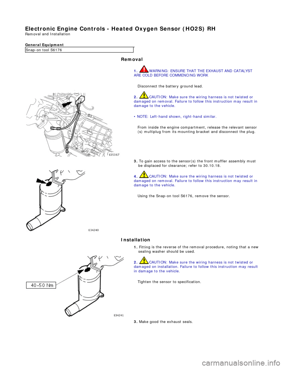
• NOTE: Left-hand shown, right-hand similar.
From inside the engine compartm ent, release the relevant sensor
(s) multiplug from its mounting bracket and disconnect the plug.
3. To
gain access to the sensor(s)
the front muffler assembly must
be displaced for clearance; refer to 30.10.18.
4. CAU
TION: Make sure the wiring harness is not twisted or
damaged on removal. Failure to follow this instruction may result in
damage to the vehicle.
Using the Snap-on tool S6176, remove the sensor.
1. Fittin
g is the reverse of the remo
val procedure, noting that a new
sealing washer should be used.
2. CAU
TION: Make sure the wiring harness is not twisted or
damaged on installation. Failure to follow this instruction may result
in damage to the vehicle.
Tighten the sensor to specification.
3. M
ake good the exhaust seals.
Page 1345 of 2490

Automatic Transmission/Transaxle - 4.0L NA V8 - AJ27/3.2L NA V8 - AJ26
- Extension Housing O-Ring Seal
In-vehicle Repair
Removal
1. Select N position.
2. Raise the vehicle for access.
3. Remove the front muffler, 30.10.18.
4. Locate a transmission jack, Epco V-100 or similar, under the
transmission unit.
пЃ¬Adjust the angle of the jack to suit the transmission.
пЃ¬Secure the side clamps.
пЃ¬Pass the safety chain over the transmission unit and
secure.
пЃ¬Take the weight of the transmission and engine.
5. Remove the engine rear mounting bracket.
1. Remove the engine rear mounting to bracket bolt.
2. Remove the mounting bracket to body bolts.
6. Gently lower the transmission jack.
7. CAUTION: Under no circumstan ces remove the driveshaft
to flexible coupling fixings.
Detach the driveshaft fro m the transmission unit.
пЃ¬Mark the position of the coupling to drive flange.
пЃ¬Remove the three bolts which secure the transmission
drive flange to the flexible coupling .
8. Remove the rear extension housing assembly.
1. Remove the ten bolts, noting their location for installation.
2. Remove and discard the O-ring.
Page 1376 of 2490

2. Reposition the tank.
8. Install engine lifting bracket 303 - 536 at the rear LH.
9. Support the engine using 303 - 021.
1. Adjust and locate the stan ds in the LH and RH fender
channels and tighten the beam fixings.
2. Engage the support hook s in the lifting brackets.
3. Tighten the support hook adjusters and take the weight of the engine.
10. Raise the vehicle for access.
11. Remove the LH downpipe cata lytic converter (17.50.09).
12. Remove the front muffler (30.10.18).
13. Remove the RH downpipe catalytic converter (17.50.09 and
17.50.10).
14. Drain the transmission fluid, (44.24.02).
15. Locate a transmission jack, Epco V-100 or similar, under the
transmission unit.
пЃ¬Adjust the angle of the jack to suit the transmission.
пЃ¬Secure the side clamps.
пЃ¬Pass the safety chain over the transmission unit and
secure.
Page 1386 of 2490

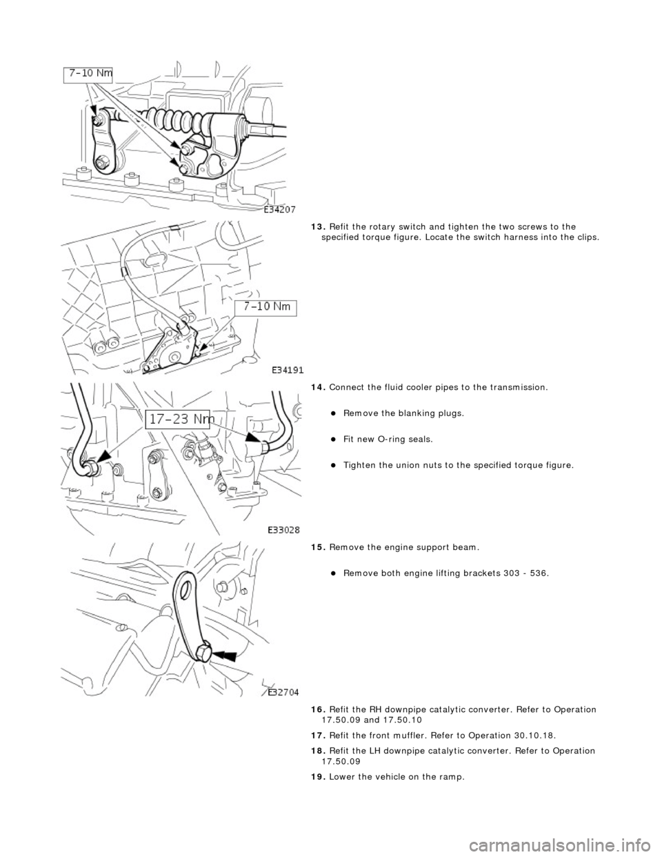
13. Refit the rotary switch and tighten the two screws to the
specified torque figure. Locate the switch harness into the clips.
14. Connect the fluid cooler pipes to the transmission.
пЃ¬Remove the blanking plugs.
пЃ¬Fit new O-ring seals.
пЃ¬Tighten the union nuts to the specified torque figure.
15. Remove the engine support beam.
пЃ¬Remove both engine lifting brackets 303 - 536.
16. Refit the RH downpipe catalytic converter. Refer to Operation
17.50.09 and 17.50.10
17. Refit the front muffler. Refer to Operation 30.10.18.
18. Refit the LH downpipe catalytic converter. Refer to Operation
17.50.09
19. Lower the vehicle on the ramp.
Page 1388 of 2490

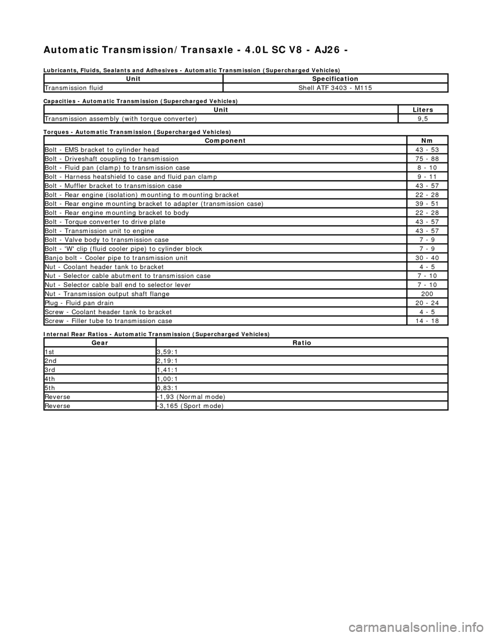
Automatic Transmission/Transaxle - 4.0L SC V8 - AJ26 -
Lubricants, Fluids, Sealants and Adhesives - Automatic Transmission (Supercharged Vehicles)
Capacities - Automatic Transmission (Supercharged Vehicles)
Torques - Automatic Transmission (Supercharged Vehicles)
Internal Rear Ratios - Automatic Transmission (Supercharged Vehicles)
UnitSpecification
Transmission fluidShell ATF 3403 - M115
UnitLiters
Transmission assembly (with torque converter)9,5
ComponentNm
Bolt - EMS bracket to cylinder head43 - 53
Bolt - Driveshaft coupling to transmission75 - 88
Bolt - Fluid pan (clamp) to transmission case8 - 10
Bolt - Harness heatshield to case and fluid pan clamp9 - 11
Bolt - Muffler bracket to transmission case43 - 57
Bolt - Rear engine (isolation) mounting to mounting bracket22 - 28
Bolt - Rear engine mounting brac ket to adapter (transmission case)39 - 51
Bolt - Rear engine mounting bracket to body22 - 28
Bolt - Torque converter to drive plate43 - 57
Bolt - Transmission unit to engine43 - 57
Bolt - Valve body to transmission case7 - 9
Bolt - 'W' clip (fluid cooler pipe) to cylinder block7 - 9
Banjo bolt - Cooler pipe to transmission unit30 - 40
Nut - Coolant header tank to bracket4 - 5
Nut - Selector cable abutment to transmission case7 - 10
Nut - Selector cable ball end to selector lever7 - 10
Nut - Transmission output shaft flange200
Plug - Fluid pan drain20 - 24
Screw - Coolant header tank to bracket4 - 5
Screw - Filler tube to transmission case14 - 18
GearRatio
1st3,59:1
2nd2,19:1
3rd1,41:1
4th1,00:1
5th0,83:1
Reverse-1,93 (Normal mode)
Reverse-3,165 (Sport mode)
Page 1433 of 2490

Automatic Transmission/Transaxle - 4.0L SC V8 - AJ26 - Extension
Housing Seal
In-vehicle Repair
Removal
Special Tool(s)
Oil seal replacer
307-378
Driveshaft wrench
205-053
1. Disconnect the battery ground lead.
2. Select N and choc the road wheels.
3. Remove the front muffler, re fer to Operation 30.10.18.
4. Remove the engine rear mounting bracket.
1. Support the transmission.
2. Remove the bolt, engine rear mounting to transmission.
3. Remove the four bolts which secure the mounting
cross member to the body.
5. Detach the driveshaft from th e transmission drive flange.
1. If the transmission is to be refitted, mark the position of the coupling relative to the drive flange.
5. CAUTION: Under no circ umstances remove the
driveshaft to flexible coupling fixings.
2. Remove the three bolts, tr ansmission drive flange to
flexible coupling.
6. Secure the driveshaft wrench 205 - 053 to the output shaft
flange.
Page 1450 of 2490

brackets.
3. Tighten the support hook adjusters to take the weight of the engine.
12. Raise the vehicle for access.
13. Remove the LH downpipe catalytic converter. Refer to
Operation 17.50.09.
14. Remove the front muffler. Re fer to Operation 30.10.18.
15. Remove the RH downpipe catalytic converter. Refer to
Operation 17.50.09 and 17.50.10.
16. Drain the transmission fluid. Refer to Operation 44.24.02.
17. Locate an Epco V-100, or sim ilar lift, under the transmission
unit.
пЃ¬Adjust the angle of the lift to suit the transmission.
пЃ¬Secure the side clamps.
пЃ¬Pass the safety chain over the transmission unit and
tighten the clamp to secure the assembly.
18. Remove the rear engine mounting bracket.
1. Remove the centre bolt from the engine/transmission
mounting.
2. Remove the four bolts which secure the mounting
bracket to the body.
19. Detach the driveshaft (prop- shaft) from the transmission
drive flange.
пЃ¬If the transmission is to be refitted, mark the position of
the coupling relative to the drive flange.
19. CAUTION: Under no circ umstances remove the
driveshaft to flexible coupling fixings.
1. Remove the transmission drive flange to flexible
coupling fixings.
Page 1454 of 2490

34. NOTE: Do not allow the converter to detach from the
transmission.
Remove the transmission / converter assembly from the
vehicle.
пЃ¬Lower the lift and remove the transmission, ensuring that
the torque converter spigot disengages cleanly.
35. Remove the side clamps and chain for access.
36. Remove the front muffler mounting bracket.
пЃ¬Remove the two bolts which secure the bracket to the
transmission case.
37. Remove the transmission dipstick tube.
1. Remove the fixing which secures the tube to the case.
пЃ¬Discard the filler tube 'O' ring. 2. Fit a blanking plug to the transmission casing orifice.
Page 1456 of 2490

Automatic Transmission/Transaxle - 4.0L SC V8 - AJ26 - Input Shaft Seal
Disassembly and Assembly of Subassemblies
Special Tool(s)
Oil seal replacer
307-378
1. Disconnect the battery ground lead.
2. Remove the air intake / MAFM assembly, refer to Operation
19.10.30.
3. Raise the vehicle for access.
4. Remove the front muffler, 30.10.18
5. Remove the RH and LH catalytic converters, refer to Operation
17.50.09 and 17.50.10.
6. Drain the transmission fluid, refer to Operation 44.24.02.
7. Remove the transmission unit, refer to Operation 44.20.01.
8. Remove the torque converter fro m the transmission unit, refer
to Operation 44.17.07.
9. Remove the front oil seal.
пЃ¬Using a proprietary tool remove the seal, taking care not
to damage the shaft or bore diameters.
10. Installation is the reverse of the removal procedure noting
that:
11. Fit the oil seal.
1. Lubricate the housing seal bore.
2. Lubricate the outside diameter of the seal.
3. Using seal replacer 307 - 379, drive the seal squarely into place.
Page 1459 of 2490

6. Fit the mounting bracket for th e front muffler. Tighten the two
bolts to the specified torque figure.
7. Secure the transmission to the engine.
пЃ¬Loosely assemble - Cooler pipe clip bolt.
пЃ¬Loosely assemble - Ground lead bolt.
пЃ¬Loosely assemble - Starter cable clips, two bolts.
пЃ¬Loosely assemble - Catalyst bracket bolts, two each side.
пЃ¬Loosely assemble - Rema ining eight bolts.
пЃ¬Refer to the illustration - tighten in sequence 1,2,3,4 then
in any order.
8. Secure the torque converter to the engine.
1. Fit, but do not tighten, the three bolts which secure the torque converter to the drive plate.
пЃ¬Prevent crankshaft rotation and tighten ALL converter
bolts to the specified torque figure.
2. Fit the blanking plug to the cylinder block access aperture.
9. Secure the oil cooler pipes.
пЃ¬Fit new Dowty washers to each union. Connect the upper
and lower cooler pipes.
пЃ¬Tighten to the specified torque figure.