regulator torque JAGUAR X308 1998 2.G Workshop Manual
[x] Cancel search | Manufacturer: JAGUAR, Model Year: 1998, Model line: X308, Model: JAGUAR X308 1998 2.GPages: 2490, PDF Size: 69.81 MB
Page 48 of 2490
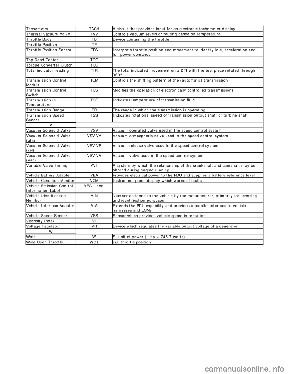
Tacho
meter
TACHA
ci
rcuit that provides input for
an electronic tachometer display
Thermal Vacuu
m Valve
TVVControls vacuum l
e
vels or
routing based on temperature
Throttle
Body
TBDe
vi
ce containing the throttle
Throttl
e
Position
TP
Throttl
e
Position Sensor
TPSInterprets throttl
e
position and movement to iden tify idle, acceleration and
full-power demands
Top Dead CenterTDC
Torque Converter C
lutch
TCC
To
tal
indicator reading
TIRThe t
o
tal indicated movement on a DTI with the test piece rotated through
360°
Transm
ission Control
Module
TCMControls
the shifting pattern
of the (automatic) transmission
Transm
ission Control
Switch
TCSModifi es
the operation of electronically controlled transmissions
Transmission Oil
TemperatureTOTIndi
cat
es temperature of transmission fluid
Transmission RangeTRThe ran
g
e in which the transmission is operating
Transmission Spe
e
d
Sensor
TSSIndi cat
es rotational speed of transmission output shaft or turbine shaft
V
Vacuu
m
Solenoid Valve
VSVVacuu
m
operated valve used in the speed control system
Vacuu
m
Solenoid Valve
(atm)
VSV VAVacuu m
atmospheric valve used in the speed control system
Vacuu
m
Solenoid Valve
(rel)
VSV VRVacuu m
release valve used in the speed control system
Vacuu
m
Solenoid Valve
(vac)
VSV VVVacuu m
valve used in the speed control system
Variable Valve TimingVVTA
s
ystem by which the relationship of the crankshaft and camshaft may be
altered during engine running
Vehi cl
e Battery Adapter
VBAProvide
s
electrical power to the PDU
and supplies a battery reference level
Vehicl
e Condition Monitor
VCMInst
rum
ent panel display which warns of faults
Ve
hic
le Emission Control
Information Label
VECI Label
Vehi cl
e Identification
Number
VINN u
mber assigned to the vehicle by the manufacturer, primarily for licensing
and identification purposes
Vehi cl
e Interface Adapter
VIAExtends the
PDU ca
pability and provid
es a parallel interface to vehicle
harnesses and ECMs
Vehicle Spe e
d Sensor
VSSSens
or which provides ve
hicle speed information
Viscosity In
dexVI
Voltage RegulatorVRDe
vice which regulates the variable output voltage of a generator
W
Wat
tWSI unit of power (1 hp = 7
45.7 watts)
W
i
de Open Throttle
WO
TFu
ll throttle position
Page 527 of 2490
E
ngine Management System Components
Electronic Throt
tle
The
electronic throttle assembly, in resp
onse to signals from both the driver and the ECM, adjusts idle speed, sets the
throttle valve to the position requested by the driver's accelerator / throttle pedal, cruise and traction control, power
limitation and catalyst warm-up.
Mass
Air Flow Meter
The sensor i
s located in the air flow mete
r assembly and outputs an analogue voltag e to the ECM. This sensor measures air
flow into the engine inlet system and is calibrated to measure kg / hour.
In
take Air Temperature
Th
e intake air temperature sensor is loca
ted in the air flow meter assembly and outputs an analogue voltage to the ECM.
The ECM will substitute a default value eq ual to 50°C should this sensor fail.
Fuel Injectors
The eigh
t bottom fed fuel injectors are located in the fuel rails. Th
e fuel injectors are electromagnetic solenoid valves
controlled by the ECM. The pulse time for the injector combined with the fuel pr essure determines the volume of fuel
injected to the manifold.
Fue
l Delivery
The fu
el pump provides fuel to the fuel rail where the circulat
ing pressure is controlled by a pressure regulator valve; excess
fuel is returned to the fuel tank.
The pressure regulator valve is controlled by manifold depression so that fuel delivery pressure is maintained at
approximately 3 bar above manifold pressure.
Fuel Pump
Relay
The ECM controls thi
s component for normal
engine running. The security system may disable this relay via communication
with the ECM.
Fuel Lev
el Sensing
The tank fuel
is measured by the fuel le
vel sensor . This signal is used by the ECM as an in put to certain diagnostics.
Eva
porative Valve
Excess vapour
formed in the fuel tank is
absorbed into the evaporative emission pu rge control canister. While the engine is
running, the fuel absorbed in the canister is gradually purged back into the engine. The rate of purging is governed by
engine operating conditions and vapour concentration level. Operating conditions which affect the purge rate are:
2—Purge
valve
3—Engine
torque reduction
4—E
lectronic throttle assembly
5—Coo
ling fans
6—Ignition amplifier driver
7—Engine overspeed
8—Cli
mate control compressor clutch
9—O
BDII information (J1962, CAN, ISO)
10—F
uel pump relay
11—Heat
ed oxygen sensor
12—Vari
able valve timing
13—MIL sw
itching
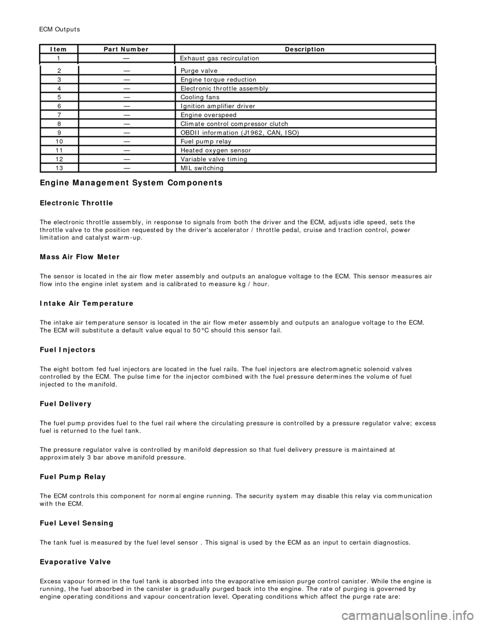
ECM Out
puts
It
em
Par
t Number
De
scription
1—Exhaus
t gas recirculation
Page 1013 of 2490
Fuel Ch
arging and Controls -
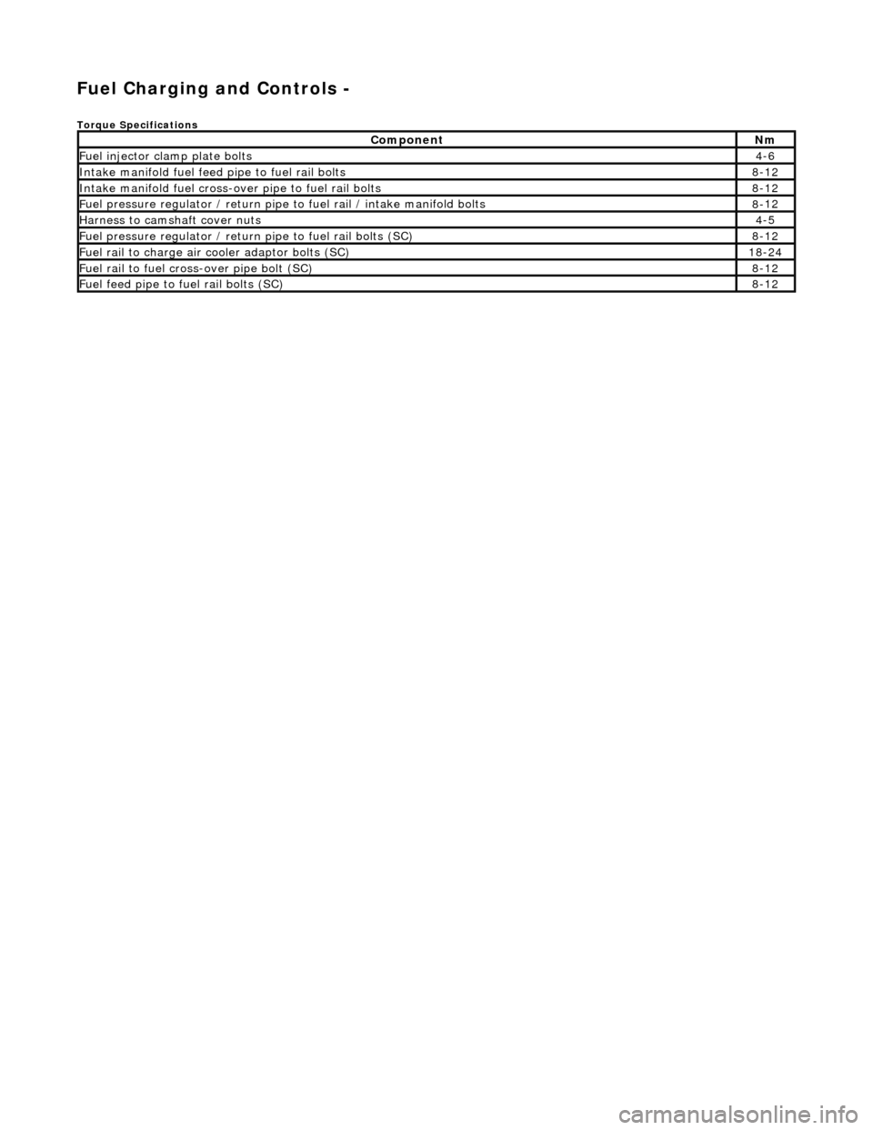
Torque Specific
ations
Com
ponent
Nm
Fue
l injector cl
amp plate bolts
4-
6
Inta
ke manifold fuel feed pipe to fuel rail bolts
8-
12
Inta
ke manifold fuel cross-over pipe to fuel rail bolts
8-
12
F
uel pressure regulator /
return pipe to fuel rail / intake manifold bolts
8-
12
Harness to
camshaft cover nuts
4-
5
F
uel pressure regulator / return
pipe to fuel rail bolts (SC)
8-
12
F
uel rail to charge air cooler adaptor bolts (SC)
18
-24
F
uel rail to fuel cross-over pipe bolt (SC)
8-
12
F
uel feed pipe to fuel rail bolts (SC)
8-
12
Page 1260 of 2490
Automatic Transmission/Transaxle - 4.0L NA V8 - AJ27/3.2L NA V8 - AJ26
-
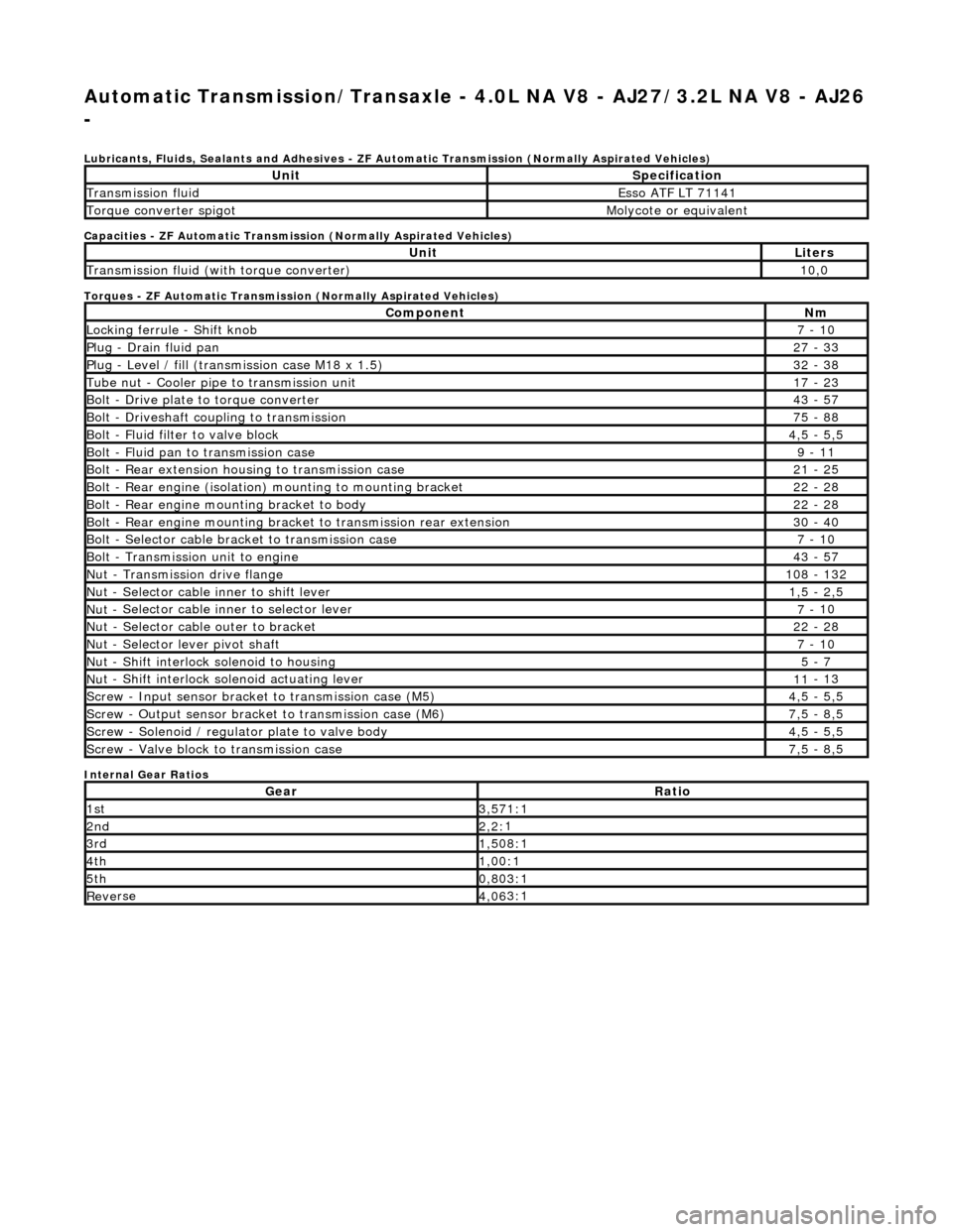
Lubri c
ants, Fluids, Sealants and Adhesives - ZF Au
tomatic Transmission (Normally Aspirated Vehicles)
Capacities - ZF Automatic Transmission (Normally Aspirated Vehicles)
Torques - ZF Automatic Transmission (Normally Aspirated Vehicles)
Internal Gear Ratios
UnitS p
ecification
Transmissi
on fluidEsso
ATF LT 71141
Torque converter spigotMolyc
o
te or equivalent
UnitLi
t
ers
Transmissi
on fluid (with
torque converter)
10
,0
Com p
onent
Nm
Locki
n
g ferrule - Shift knob
7 -
10
P
l
ug - Drain fluid pan
27
-
33
P
l
ug - Level / fill (transmission case M18 x 1.5)
32
-
38
Tu
be
nut - Cooler pipe to transmission unit
17
-
23
B
o
lt - Drive plate to torque converter
43
-
57
B
o
lt - Driveshaft coupling to transmission
75
-
88
Bo
lt
- Fluid filter to valve block
4,
5 -
5,5
Bolt
-
Fluid pan to transmission case
9 -
11
B
o
lt - Rear extension housing to transmission case
21
-
25
Bolt
-
Rear engine (isolation) mounting to mounting bracket
22
-
28
Bolt -
Rear engine moun
ting bracket to body
22
-
28
Bolt
-
Rear engine mounting bracke
t to transmission rear extension
30 -
40
B
o
lt - Selector cable bracket to transmission case
7 -
10
Bolt
-
Transmission unit to engine
43
-
57
Nu
t -
Transmission drive flange
1
08 -
132
Nu
t -
Selector cable inner to shift lever
1,
5 -
2,5
Nu
t -
Selector cable inner to selector lever
7 -
10
Nu
t -
Selector cable outer to bracket
22
-
28
Nu
t
- Selector lever pivot shaft
7 -
10
Nu
t -
Shift interlock solenoid to housing
5 -
7
Nut -
Shift interlock solenoid actuating lever
11
-
13
Sc
re
w - Input sensor bracket to transmission case (M5)
4,
5 -
5,5
Screw
-
Output sensor bracket to transmission case (M6)
7,
5 -
8,5
Screw
-
Solenoid / regulator plate to valve body
4,
5 -
5,5
Sc
re
w - Valve block to transmission case
7,
5 -
8,5
GearRatio
1s
t3,57
1:1
2n
d2,2:
1
3r
d1,50
8:1
4t
h1,00
:1
5t
h0,80
3:1
Re
ve
rse
4,
06
3:1
Page 1262 of 2490
Contains th
e hydraulic system pump.
Contains
th
e fluid temperature sensor.
The epicyclic geartrain:
Provi des fi
ve forward gears and Reverse.
Has
h
ydraulically actuated, multi-disk clutches, to select the required gear ratios.
Feature
s clutch-to-clutch operation to permit
gear shifts for uninterrupted power flow.
The electro-hydraulic control unit:
Is lo c
ated in the lower part of
the unit, within the fluid pan.
Is controlled
by the TCM (transmissio
n control module), and the manual selector valve which is cable operated.
Re
gulates the flow of fluid to the ge
artrain clutches via three solenoid-operated valv es and the manual selector
valve.
Has fi ve pressure
regulators for controll
ing fluid pressures within the system.
Is con
nected to the TCM via a 16-way connector mounted on
the left-hand side of the transmission casing. Refer to
Connector Pins Identification, Section 307-01A.
The hydraulic system pump:
Is l o
cated at the front of the transmission casing.
Is dri
v
en from the impeller hub,
pressurising the fluid whenever the engine is running.
Supplie
s fluid under pressure to the torq
ue converter, geartrain, electro-hydr aulic control unit and the lubrication
circuit.
D r
aws fluid from the fluid pa
n below the transmission casing, through a filter.
The rear extension housing:
Is bolt
ed to the rear of the transmission casing.
Provides the rear engine / transmi
ssion mo
unting point; refer to section 303-01.
Carrie
s the transmission output shaft oil seal.
Filled-for-l
i
fe Fluid System
The
transm
ission is 'filled for life' and
does not require fluid changes, except where extreme driving conditions prevail.
Routine level checking is not required and a dipstick is not pr ovided. A level / filler plug is fitted for level checking and
replenishment, following service actions; see 303-01 General Procedures.
Transmission Torque Converter
Page 1263 of 2490
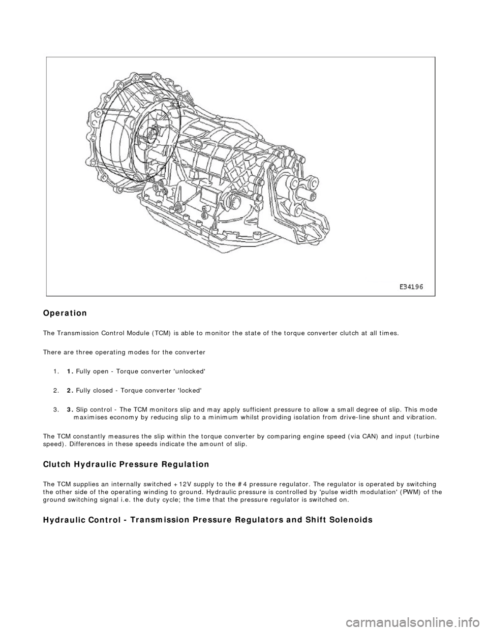
Op
eration
The T
ransmission Control Module (TCM) is
able to monitor the state of the torque converter clut ch at all times.
There are three operating modes for the converter
1. 1. Fully open - Torque converter 'unlocked'
2. 2. Fully closed - Torque converter 'locked'
3. 3. Slip control - The TCM monitors slip and may apply sufficie nt pressure to allow a small degree of slip. This mode
maximises economy by reducing slip to a minimum whilst providing isolation from drive-line shunt and vibration.
The TCM constantly measures the slip within the torque conver ter by comparing engine speed (via CAN) and input (turbine
speed). Differences in these speeds indicate the amount of slip.
Clutch Hydraulic Pressure Regulation
The T
CM supplies an internally switched +1
2V supply to the #4 pressure regulator. The regulator is operated by switching
the other side of the operating winding to ground. Hydraulic pressure is controlled by 'pulse width modulation' (PWM) of the
ground switching signal i.e. the duty cycle; the time that the pressure regulator is switched on.
Hydraulic Control
- Transmission Pre
ssure Regulators an d Shift Solenoids
Page 1268 of 2490
Input speed is monitored by the TCM with a rationality check being made against output speed. A fault will be flagged if the
indicated input speed exceeds 7400 rpm. Additionally, a failure judgement will be made if the indicated input speed is <160
rpm with engine speed >608 rpm and output speed >224 rpm
The procedure is similar for the output sp eed diagnostic. A fault (non OBDII) will be flagged if the indicated input speed
exceeds 6712 rpm. Additionally a failure judgement will be ma de if the indicated output speed is <160 rpm and the average
road wheel speed exceeds 100 rpm.
Under normal circumstance s after the output speed diagnost ic fault code has been set, the TCM uses rear wheel speed
information to compute its calculations, this has no effect on transmission operation. However, should a second fault occur,
in the ABS system, thus making rear wheel speed information unavailable, an additional fault code will be logged.
Control Systems
Introduction
Gear selection is achieved by controlling the flow of transmission fluid to internal multi-disc clutches.
The three solenoid valves direct the transmission fluid flow to the selected clutches and the pressure regulators control the
fluid pressure to each component. One pr essure regulator serves as a master pressure control for the entire system and a
second is used exclusively for torque converter clutch lock-up operation.
The TCM controls the internal components thus determining gear selection and shift pattern.
In the event of an electronic system fault the basic function s Park, Reverse Neutral and Drive Fourth are retained by the
hydraulic system.
Transmission Control Module (TCM)
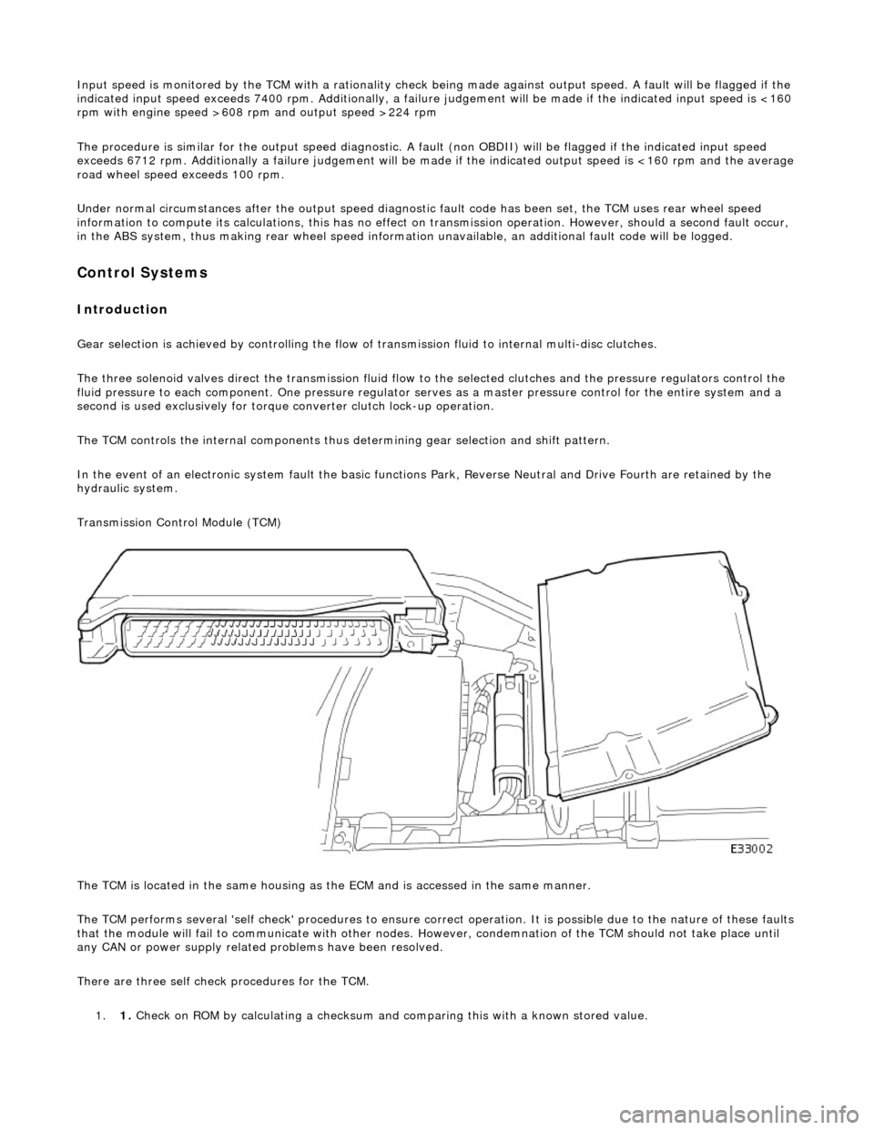
The TCM is located in the same housing as th e ECM and is accessed in the same manner.
The TCM performs several 'self check' procedur es to ensure correct operation. It is possible due to the nature of these faults
that the module will fail to communicate with other nodes. However, condemnation of the TCM should not take place until
any CAN or power supply related problems have been resolved.
There are three self check procedures for the TCM. 1. 1. Check on ROM by calculatin
g a checksum and comparing this with a known stored value.
Page 1275 of 2490
Automatic Transmission/Transaxle - 4.0L NA V8 - AJ27/3.2L NA V8 - AJ26
- Diagnostic Strategy
Diagnosis and Testing
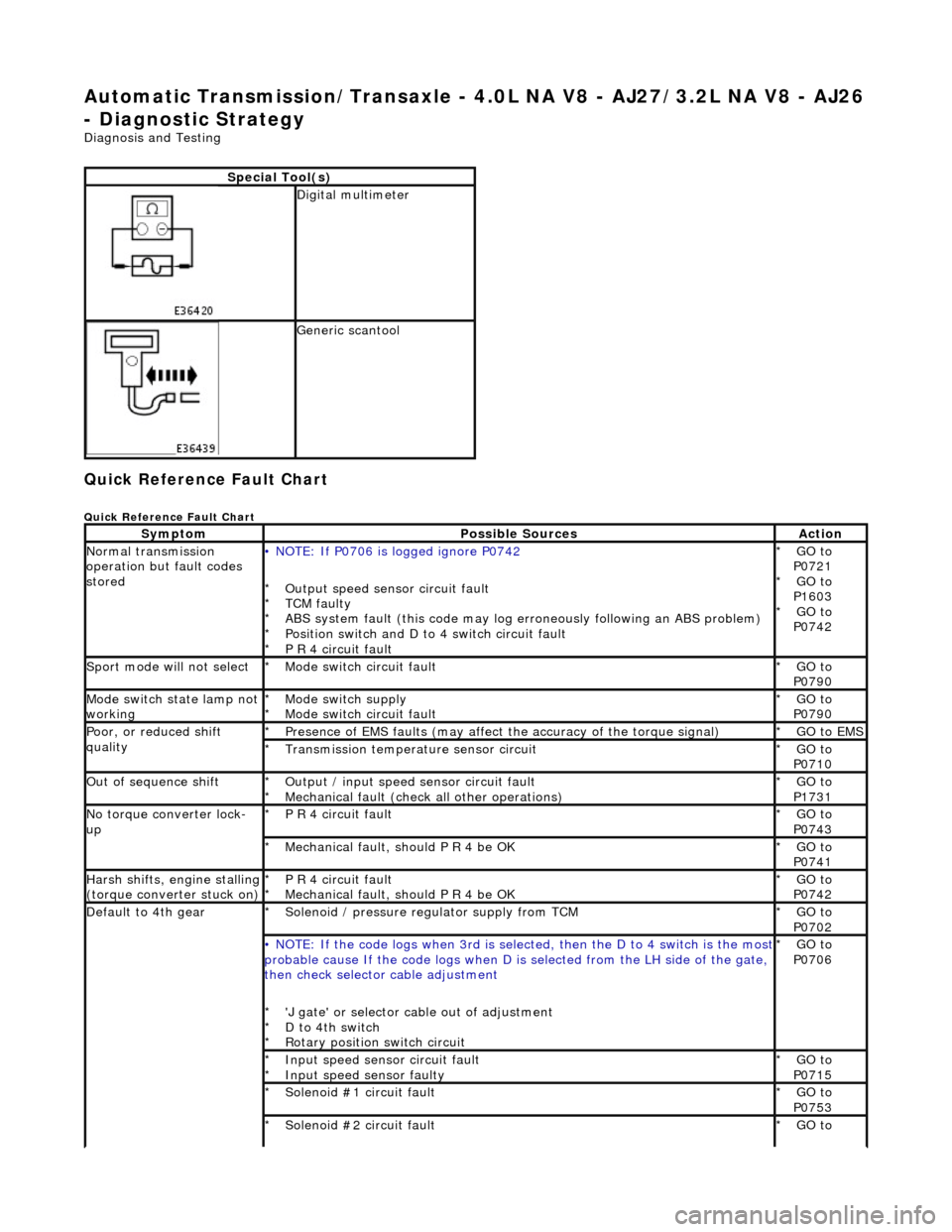
Quick Reference Fault Chart
Quick Reference Fault Chart
Special Tool(s)
Digital multimeter
Generic scantool
SymptomPossible SourcesAction
Normal transmission
operation but fault codes
stored• NOTE: If P0706 is logged ignore P0742
Output speed sensor circuit fault
TCM faulty
ABS system fault (this code may log er roneously following an ABS problem)
Position switch and D to 4 switch circuit fault
P R 4 circuit fault
*
*
*
*
*
GO to
P0721 GO to
P1603 GO to
P0742
*
*
*
Sport mode will not selectMode switch circuit fault
*GO to
P0790
*
Mode switch state lamp not
workingMode switch supply
Mode switch circuit fault
*
*GO to
P0790
*
Poor, or reduced shift
qualityPresence of EMS faults
(may affect the accuracy of the torque signal)
*GO to EMS *
Transmission temperature sensor circuit
*GO to
P0710
*
Out of sequence shiftOutput / input speed sensor circuit fault
Mechanical fault (check all other operations)
*
*GO to
P1731
*
No torque converter lock-
upP R 4 circuit fault
*GO to
P0743
*
Mechanical fault, should P R 4 be OK
*GO to
P0741
*
Harsh shifts, engine stalling (torque converter stuck on)P R 4 circuit fault
Mechanical fault, should P R 4 be OK
*
*GO to
P0742
*
Default to 4th gearSolenoid / pressure regulator supply from TCM
*GO to
P0702
*
• NOTE: If the code logs wh
en 3rd is selected, then the D to 4 switch is the most probable cause If the code logs when D is selected fro m the LH side of the gate,
then check selector cable adjustment
'J gate' or selector ca ble out of adjustment
D to 4th switch
Rotary position switch circuit
*
*
*GO to
P0706
*
Input speed sensor circuit fault
Input speed sensor faulty
*
*GO to
P0715
*
Solenoid #1 circuit fault
*GO to
P0753
*
Solenoid #2 circuit fault
*GO to
*
Page 1276 of 2490
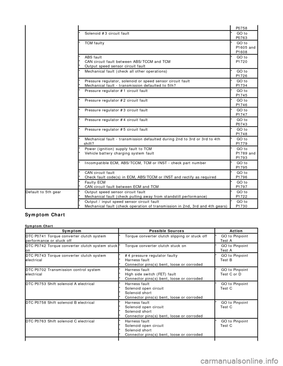
Symptom Chart
Symptom Chart
P0758
Solenoid #3 circuit fault
*GO to
P0763
*
TCM faulty
*GO to
P1605 and
P1608
*
ABS fault
CAN circuit fault between ABS/TCCM and TCM
Output speed sensor circuit fault
*
*
*GO to
P1720
*
Mechanical fault (check all other operations)
*GO to
P1726
*
Pressure regulator, solenoid
or speed sensor circuit fault
Mechanical fault - transmission defaulted to 5th?
*
*GO to
P1734
*
Pressure regulator #1 circuit fault
*GO to
P1745
*
Pressure regulator #2 circuit fault
*GO to
P1746
*
Pressure regulator #3 circuit fault
*GO to
P1747
*
Pressure regulator #4 circuit fault
*GO to
P0743
*
Pressure regulator #5 circuit fault
*GO to
P1748
*
Mechanical fault - transmission defaul
ted during 2nd to 3rd or 3rd to 4th
shift?
*GO to
P1779
*
Power (ignition) supply fault to TCM
Vehicle battery charging system fault
*
*GO to
P1789 and
P1793
*
Incompatible ECM, ABS/TCCM, TCM or INST - check part number
*GO to
P1795
*
CAN circuit fault
Check fault code(s) in ECM, ABS/TCCM or INST and rectify as required
*
*GO to
P1796
*
Faulty ECM
CAN circuit fault between ECM and TCM
*
*GO to
P1797
*
Default to 5th gearOutput speed sensor circuit fault
Mechanical fault (check pulling
away from standstill performance)
*
*GO to
P1722
*
Output / input speed sensor circuit fault
Mechanical fault (check operation of tr
ansmission in 2nd, 3rd and 4th gears)
*
*GO to
P1730
*
SymptomPossible SourcesAction
DTC P0741 Torque converter clutch system
performance or stuck offTorque converter clutch slipping or stuck off
*GO to Pinpoint
Test A
*
DTC P0742 Torque converter clutch system stuck onTorque converter clutch stuck on
*GO to Pinpoint
Test A
*
DTC P0743 Torque converter clutch system
electrical#4 pressure regulator faulty
Harness fault
Connector pins(s) bent
, loose or corroded
*
*
*GO to Pinpoint
Test B
*
DTC P0702 Transmission control system
electricalHarness fault
High side switch (FET) fault
Connector pins(s) bent
, loose or corroded
*
*
*GO to Pinpoint
Test C or D
*
DTC P0753 Shift solenoid A electricalHarness fault
Solenoid open circuit
Solenoid short
Connector pins(s) bent
, loose or corroded
*
*
*
*GO to Pinpoint
Test C
*
DTC P0758 Shift solenoid B electricalHarness fault
Solenoid open circuit
Solenoid short
Connector pins(s) bent
, loose or corroded
*
*
*
*GO to Pinpoint
Test C
*
DTC P0763 Shift solenoid C electricalHarness fault
Solenoid open circuit
Solenoid short
Connector pins(s) bent
, loose or corroded
*
*
*
*GO to Pinpoint
Test C
*
Page 1277 of 2490
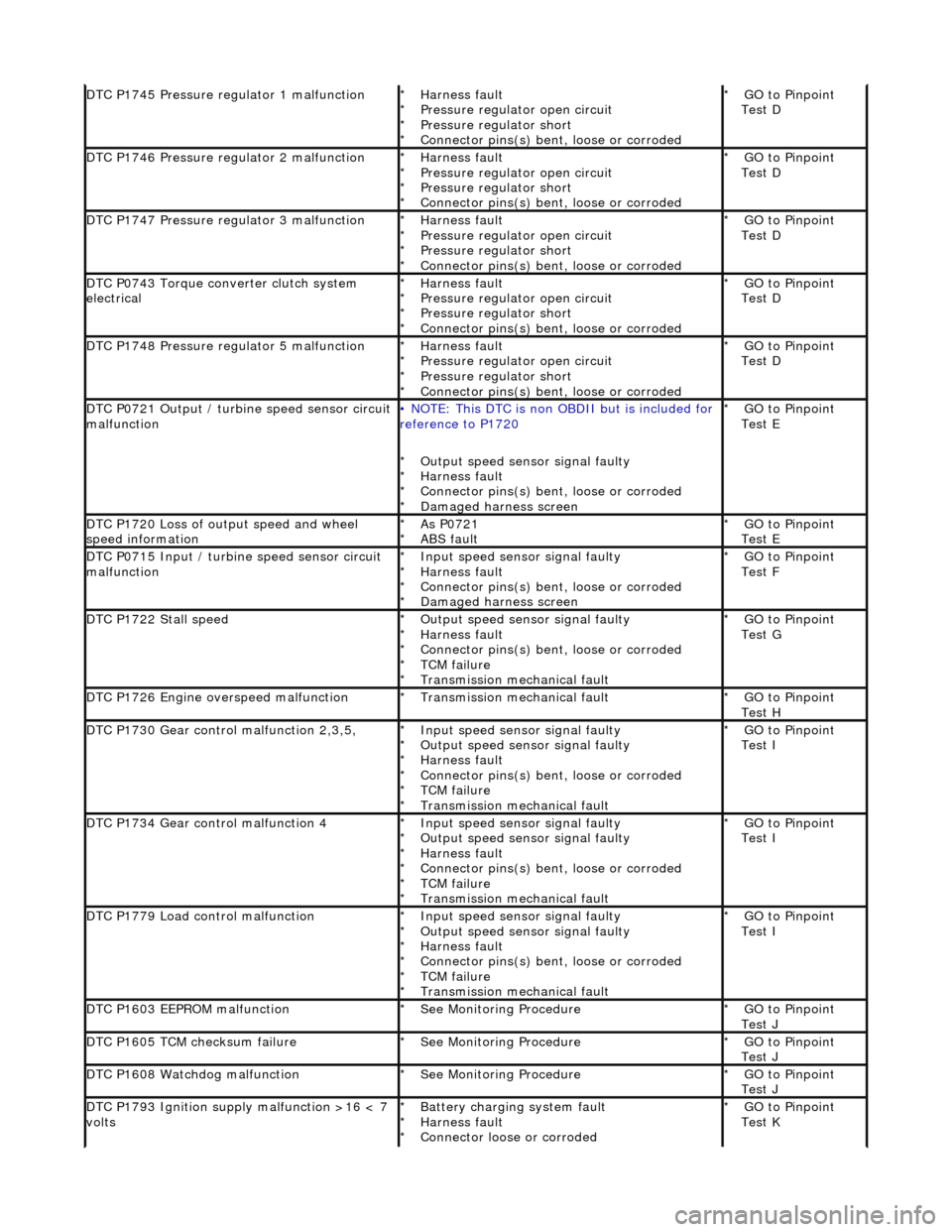
DTC P1745 Pressure regulator 1 malfunctionHarness fault
Pressure regulator open circuit
Pressure regulator short
Connector pins(s) bent, loose or corroded
*
*
*
*GO to Pinpoint
Test D
*
DTC P1746 Pressure regulator 2 malfunctionHarness fault
Pressure regulator open circuit
Pressure regulator short
Connector pins(s) bent
, loose or corroded
*
*
*
*GO to Pinpoint
Test D
*
DTC P1747 Pressure regulator 3 malfunctionHarness fault
Pressure regulator open circuit
Pressure regulator short
Connector pins(s) bent
, loose or corroded
*
*
*
*GO to Pinpoint
Test D
*
DTC P0743 Torque converter clutch system
electricalHarness fault
Pressure regulator open circuit
Pressure regulator short
Connector pins(s) bent
, loose or corroded
*
*
*
*GO to Pinpoint
Test D
*
DTC P1748 Pressure regulator 5 malfunctionHarness fault
Pressure regulator open circuit
Pressure regulator short
Connector pins(s) bent
, loose or corroded
*
*
*
*GO to Pinpoint
Test D
*
DTC P0721 Output / turbine speed sensor circuit
malfunction• NOTE: This DTC is non OBDII but is included for
reference to P1720
Output speed sensor signal faulty
Harness fault
Connector pins(s) bent , loose or corroded
Damaged harness screen
*
*
*
*GO to Pinpoint
Test E
*
DTC P1720 Loss of output speed and wheel
speed informationAs P0721
ABS fault
*
*GO to Pinpoint
Test E
*
DTC P0715 Input / turbine speed sensor circuit
malfunctionInput speed sensor signal faulty
Harness fault
Connector pins(s) bent
, loose or corroded
Damaged harness screen
*
*
*
*GO to Pinpoint
Test F
*
DTC P1722 Stall speedOutput speed sensor signal faulty
Harness fault
Connector pins(s) bent
, loose or corroded
TCM failure
Transmission mechanical fault
*
*
*
*
*GO to Pinpoint
Test G
*
DTC P1726 Engine overspeed malfunctionTransmission mechanical fault
*GO to Pinpoint
Test H
*
DTC P1730 Gear control malfunction 2,3,5,Input speed sensor signal faulty
Output speed sensor signal faulty
Harness fault
Connector pins(s) bent
, loose or corroded
TCM failure
Transmission mechanical fault
*
*
*
*
*
*GO to Pinpoint
Test I
*
DTC P1734 Gear control malfunction 4Input speed sensor signal faulty
Output speed sensor signal faulty
Harness fault
Connector pins(s) bent
, loose or corroded
TCM failure
Transmission mechanical fault
*
*
*
*
*
*GO to Pinpoint
Test I
*
DTC P1779 Load control malfunctionInput speed sensor signal faulty
Output speed sensor signal faulty
Harness fault
Connector pins(s) bent
, loose or corroded
TCM failure
Transmission mechanical fault
*
*
*
*
*
*GO to Pinpoint
Test I
*
DTC P1603 EEPROM malfunctionSee Monitoring Procedure
*GO to Pinpoint
Test J
*
DTC P1605 TCM checksum failureSee Monitoring Procedure
*GO to Pinpoint
Test J
*
DTC P1608 Watchdog malfunctionSee Monitoring Procedure
*GO to Pinpoint
Test J
*
DTC P1793 Ignition supply malfunction >16 < 7
voltsBattery charging system fault
Harness fault
Connector loose or corroded
*
*
*GO to Pinpoint
Test K
*