toe in JAGUAR X308 1998 2.G Workshop Manual
[x] Cancel search | Manufacturer: JAGUAR, Model Year: 1998, Model line: X308, Model: JAGUAR X308 1998 2.GPages: 2490, PDF Size: 69.81 MB
Page 2 of 2490

TABLE OF CONTENTS
1: General Information
100:
Service Information
100‐00: General Information
Description and Operation
General Service Information
Terminology Glossary
100‐01: Identification Codes
Description and Operation
Identification Codes
100‐02: Jacking and Lifting
Description and Operation
Jacking
Safety Precautions
Vehicle Recovery
General Procedures
Using the Vehicle Ja
ck
Using the Workshop Jack
2: Chassis
204: Suspension
204‐00: Suspension System ‐ General Information
Specification
General
Procedures
Front
Camber and Caster Adjustment (57.65.02)
Front
Camber, Caster and Toe Adjustment (57.65.03)
Front
Toe Adjustment (57.65.01)
Page 3 of 2490

Rear Toe Adjustment (57.65. 08)
Whee
l
Bearing Circlip Inspection
Wheel Bearing Inspection
204‐01: Front Suspension
Specification
Description and Operation
Front Suspension
Removal and Installation
Ball Joint (60.15.02)
Rear Lower Arm (60.35.54)
Rear Lower Arm Bushing (60.35.56)
Front Shock Absorber (60.30.04)
Spring
Spring Seat (60.20.03)
Front Sta
bilizer Bar (60.10.01)
Front Stabilizer Bar Bushing (60.10.04)
Front Stabilizer Bar Link (60.10.02)
Upper Arm Bushing
Front Wheel Bearing (60.25.40)
Wheel Hub
Wheel Knuckle (60.25.23)
Wheel Knuckle and Wheel Hub Assembly (60.25.38.90)
Wheel Knuckle and Wheel Hub Assembly Conversion (60.25.43)
204‐02: Rear Suspension
Specif
ication
Description and Operation
Rear Suspension
Removal and Installation
Axle Bump Stop (64.30.15)
Rear Suspension and Axle Assembly (64.25.01)
Rear Shock Absorber (64.30.02)
Shock Absorber Lower Bushing (64.30.39)
Spring (64.20.01)
Rear Stabilizer Bar (64.35.08) ‐ 4.0L SC V8 ‐ AJ26
Rear Stabilizer Bar Bushing (64.35.18) ‐ 4.0L SC V8 ‐ AJ26
Page 59 of 2490
Al
l the above figures
are at "showroom" height. (See ride height section above).
Ti
res must be inflated
to normal pressure.
For additional informat ion, refer to Section 204
-0
4 Wheels and Tires
.
Whe
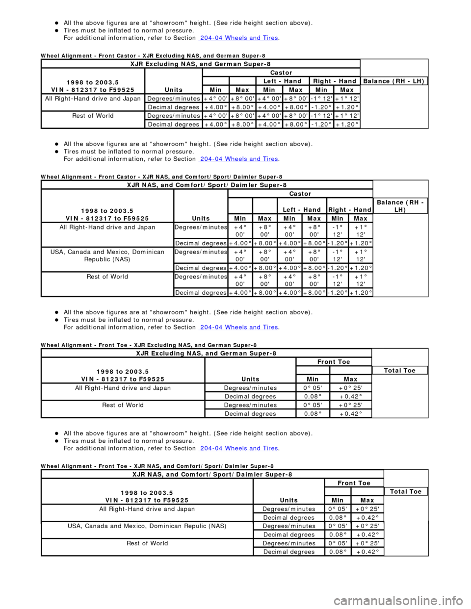
el Alignment - Front Castor - XJR Excluding NAS, and German Super-8
Al
l the above figures
are at "showroom" height. (See ride height section above).
Ti
res must be inflated
to normal pressure.
For additional informat ion, refer to Section 204
-0
4 Wheels and Tires
.
Whe
el Alignment - Front Castor - XJR NAS, and Comfort/Sport/Daimler Super-8
Al
l the above figures
are at "showroom" height. (See ride height section above).
Ti
res must be inflated
to normal pressure.
For additional informat ion, refer to Section 204
-0
4 Wheels and Tires
.
Whe
el Alignment - Front Toe - XJR Excluding NAS, and German Super-8
Al
l the above figures
are at "showroom" height. (See ride height section above).
Ti
res must be inflated
to normal pressure.
For additional informat ion, refer to Section 204
-0
4 Wheels and Tires
.
Whe
el Alignment - Front Toe - XJR NAS, and Comfort/Sport/Daimler Super-8
XJR
Excluding NAS, and German Super-8
1
998 to 2003.5
VIN - 812317 to F59525
Units
Castor
Le
ft - Hand
Rig
ht - Hand
Bal
ance (RH - LH)
MinMaxMinMaxMinMax
All Right
-Hand drive and Japan
De
grees/minutes
+4
° 00'
+8
° 00'
+4
° 00'
+8
° 00'
-1
° 12'
+1
° 12'
Decimal degrees+4
.00°
+8
.00°
+4
.00°
+8
.00°
-1.
20°
+1
.20°
R
est of World
De
grees/minutes
+4
° 00'
+8
° 00'
+4
° 00'
+8
° 00'
-1
° 12'
+1
° 12'
Decimal degrees+4
.00°
+8
.00°
+4
.00°
+8
.00°
-1.
20°
+1
.20°
XJR
NAS, and Comfort/Sport/Daimler Super-8
1
998 to 2003.5
VIN - 812317 to F59525
Units
Castor
Le
ft - Hand
Rig
ht - Hand
Bal
ance (RH -
LH)
MinMaxMinMaxMinMax
All Right
-Hand drive and Japan
De
grees/minutes
+4
°
00'
+8
°
00'
+4
°
00'
+8
°
00'
-1
°
12'
+1
°
12'
Decimal degrees+4
.00°
+8
.00°
+4
.00°
+8
.00°
-1.
20°
+1
.20°
USA, Canada an
d Mexico, Dominican
Republic (NAS)
De
grees/minutes
+4
°
00'
+8
°
00'
+4
°
00'
+8
°
00'
-1
°
12'
+1
°
12'
Decimal degrees+4
.00°
+8
.00°
+4
.00°
+8
.00°
-1.
20°
+1
.20°
R
est of World
De
grees/minutes
+4
°
00'
+8
°
00'
+4
°
00'
+8
°
00'
-1
°
12'
+1
°
12'
Decimal degrees+4
.00°
+8
.00°
+4
.00°
+8
.00°
-1.
20°
+1
.20°
XJR
Excluding NAS, and German Super-8
1
998 to 2003.5
VIN - 812317 to F59525
Units
Fr
ont Toe
To
tal Toe
MinMax
All Right-Hand driv
e and Japan
De
grees/minutes
0
° 05'
+0
° 25'
Decimal degrees0.
08°
+0
.42°
R
est of World
De
grees/minutes
0
° 05'
+0
° 25'
Decimal degrees0.
08°
+0
.42°
XJR
NAS, and Comfort/Sport/Daimler Super-8
1
998 to 2003.5
VIN - 812317 to F59525
Units
Fr
ont Toe
To
tal Toe
MinMax
All Right-Hand driv
e and Japan
De
grees/minutes
0
° 05'
+0
° 25'
Decimal degrees0.
08°
+0
.42°
USA, Canada an
d Mexico
, Dominican Repulic (NAS)
De
grees/minutes
0
° 05'
+0
° 25'
Decimal degrees0.
08°
+0
.42°
R
est of World
De
grees/minutes
0
° 05'
+0
° 25'
Decimal degrees0.
08°
+0
.42°
Page 60 of 2490
All the above fi
gures
are at "showroom" height. (See ride height section above).
Tires must be infl
ated
to normal pressure.
For additional informat ion, refer to Section 204
-04
Wheels and Tires
.
Wh
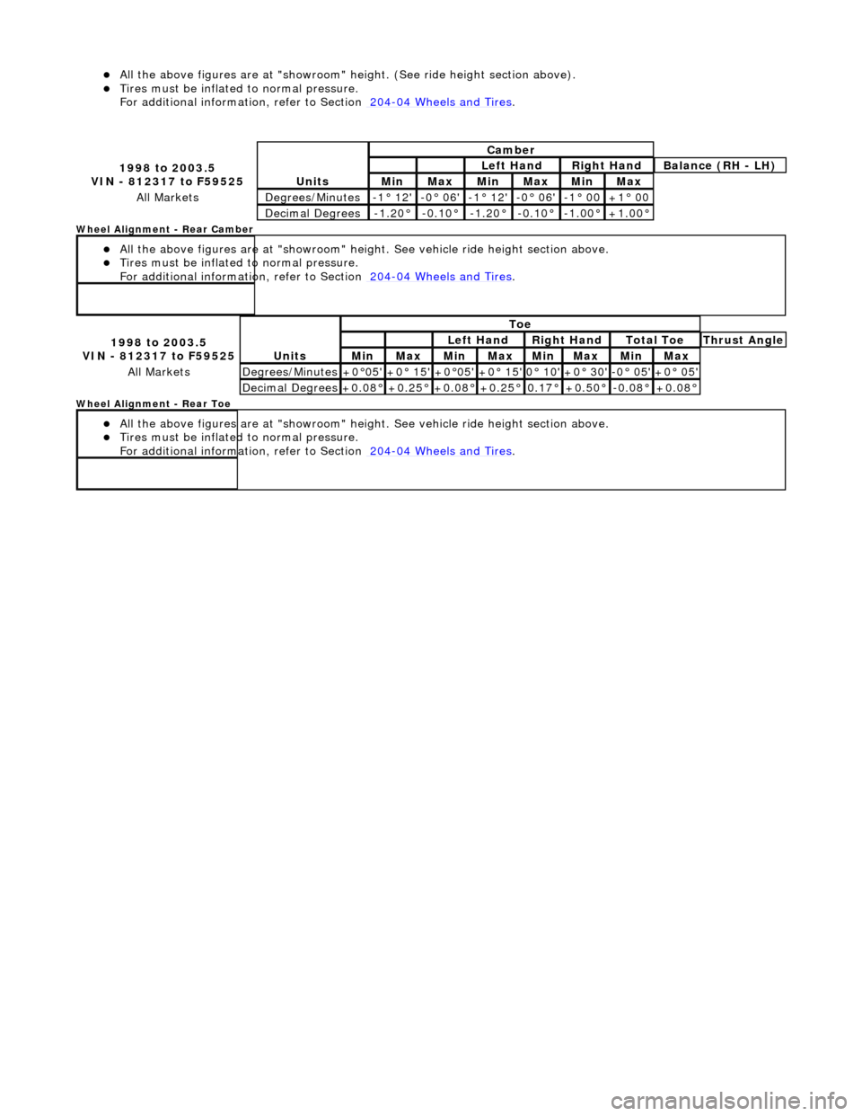
eel Alignment - Rear Camber
All the above figu res
are at "s
howroom" height. See vehicle ride height section above.
Tires must be infl
ated
to normal pressure.
For additional informat ion, refer to Section 204
-04
Wheels and Tires
.
W
h
eel Alignment - Rear Toe
All the above figu res
are at "s
howroom" height. See vehicle ride height section above.
Tires must be infl
ated
to normal pressure.
For additional informat ion, refer to Section 204
-04
Wheels and Tires
.
1 998 to
2003.5
VIN - 812317 to F59525
Units
Cambe r
Left
Hand
Rig
h
t Hand
Bal
a
nce (RH - LH)
Min MaxMin MaxMinMax
All MarketsDe
grees
/Minutes
-
1
° 12'
-0
° 06'-1° 12'-0
° 06'
-1
°
00
+1
°
00
De
ci
mal Degrees
-1.
2
0°
-0
.1
0°
-1.
2
0°
-0.
1
0°
-1.
0
0°
+1
.00
°
1
998 to
2003.5
VIN - 812317 to F59525
Units
To e
Left
Hand
Rig
h
t Hand
To
t
al Toe
Thr
u
st Angle
MinMaxMinMaxMin MaxMin Max
All MarketsDe
grees
/Minutes
+0
°
05'
+0
° 15'+0°
05'
+0
° 15'0°
10'
+0
° 30'-0° 05'+0 °
05'
De
ci
mal Degrees
+0
.08
°
+0
.25
°
+0
.08
°
+0
.25
°
0.
17
°
+0
.50
°
-0.
0
8°
+0
.08
°
Page 62 of 2490
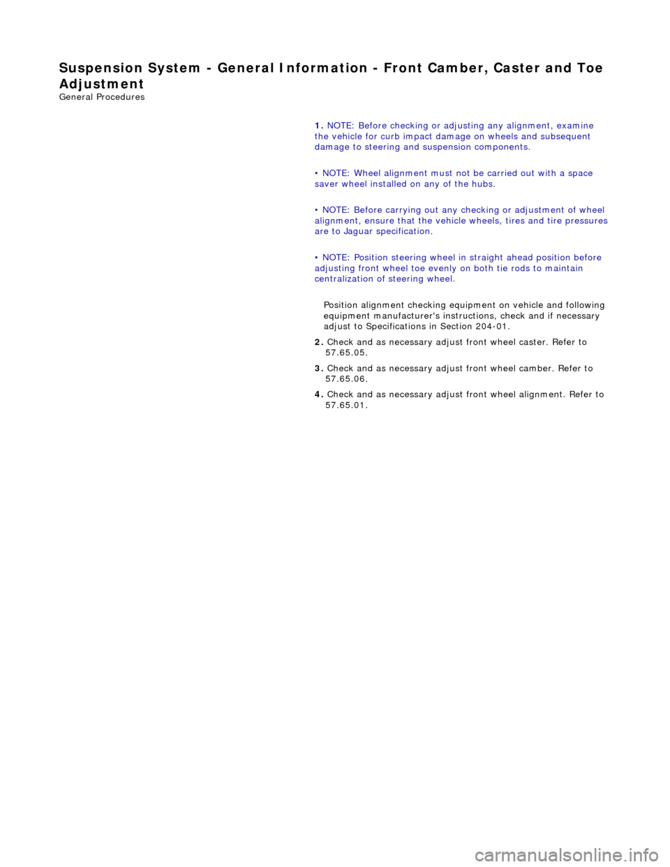
Suspension System - General Information - Front Camber
, Caster and Toe
Adjustment
Gen e
ral Procedures
1.
NOTE: Before checking or adju sting any alignment, examine
the vehicle for curb impact dama ge on wheels and subsequent
damage to steering and suspension components.
• NOTE: Wheel alignment must no t be carried out with a space
saver wheel installed on any of the hubs.
• NOTE: Before carrying out any ch ecking or adjustment of wheel
alignment, ensure that the vehicl e wheels, tires and tire pressures
are to Jaguar specification.
• NOTE: Position steering wheel in straight ahead position before
adjusting front wheel toe evenly on both tie rods to maintain
centralization of steering wheel.
Position alignment checking equipment on vehicle and following
equipment manufacturer's instructions, check and if necessary
adjust to Specifications in Section 204-01.
2. Check and as necessary adjust front wheel caster. Refer to
57.65.05.
3. Check and as necessary adjust front wheel camber. Refer to
57.65.06.
4. Check and as necessary adjust fr ont wheel alignment. Refer to
57.65.01.
Page 63 of 2490
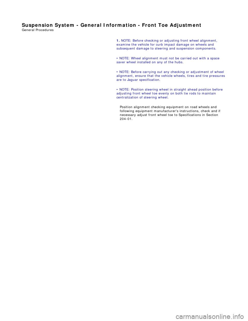
Suspension System - General Infor
mation - Front Toe Adjustment
Gen
eral Procedures
1.
NOTE: Before checking or adju sting front wheel alignment,
examine the vehicle for curb impact damage on wheels and
subsequent damage to steering and suspension components.
• NOTE: Wheel alignment must no t be carried out with a space
saver wheel installed on any of the hubs.
• NOTE: Before carrying out any ch ecking or adjustment of wheel
alignment, ensure that the vehicl e wheels, tires and tire pressures
are to Jaguar specification.
• NOTE: Position steering wheel in straight ahead position before
adjusting front wheel toe evenly on both tie rods to maintain
centralization of steering wheel.
Position alignment checking equipment on road wheels and
following equipment manufacturer's instructions, check and if
necessary adjust front wheel toe to Specifications in Section
204-01.
Page 64 of 2490
Suspension System - General Inform
ation - Rear Toe Adjustment
Gen
e
ral Procedures
1.
NOTE: Wheel alignment must not be carried out with a space
saver wheel installed on any of the hubs.
• NOTE: Before carrying out any ch ecking or adjustment of wheel
alignment, ensure that the vehicl e wheels, tires and tire pressures
are to Jaguar specification.
• NOTE: Before checking or ad justing rear wheel alignment,
examine the vehicle for curb impact damage on wheels and
subsequent damage to suspension components.
Position alignment checking equipment on road wheels and
following equipment manufacturer's instructions, check and if
necessary adjust rear wheel alignment to Specifications in
Section 204-02.
Page 167 of 2490
Rear
Suspension - Rear Suspension
Description an
d Operation
Description
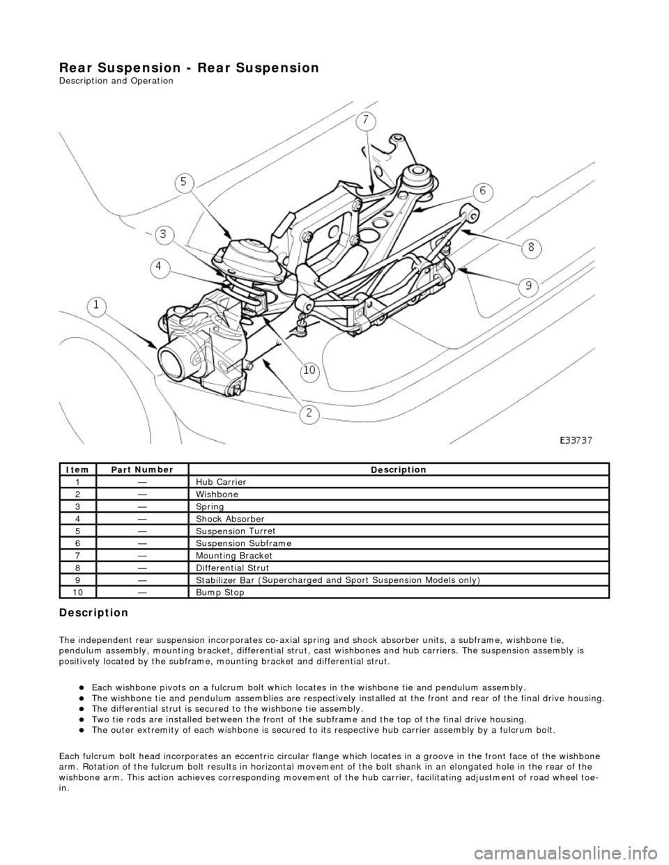
The i
ndependent rear suspension incorporates co-axial sp
ring and shock absorber units, a subframe, wishbone tie,
pendulum assembly, mounting brac ket, differential strut, cast wishbones and hub carriers. The suspension assembly is
positively located by the subframe, mounting bracket and differential strut.
Each wi
shbone pivots on a fulcru
m bolt which locates in the wishbone tie and pendulum assembly.
The wish
bone tie and pendulum assemblies are respectively in
stalled at the front and rear of the final drive housing.
The differential
strut is secured to the wishbone tie assembly.
Two ti
e rods are installed between the front of the
subframe and the top of the final drive housing.
The ou
ter extremity of each wishbone
is secured to its respective hub carrier assembly by a fulcrum bolt.
Each fulcrum bolt head incorporates an ec centric circular flange which locates in a groove in the front face of the wishbone
arm. Rotation of the fulcrum bolt results in horizontal movement of the bolt shank in an elongated hole in the rear of the
wishbone arm. This acti on achieves corresponding movement of the hub carrier, facilita ting adjustment of road wheel toe-
in.
It
em
Par
t Number
De
scription
1—Hub Carrier
2—Wi
shbone
3—Sprin
g
4—Shock Absorber
5—Suspensi
on Turret
6—Suspensi
on Subframe
7—Moun
ting Bracket
8—D
ifferential Strut
9—Stabilizer Ba
r (Supercharged and
Sport Suspension Models only)
10—Bum
p Stop
Page 266 of 2490
WHE
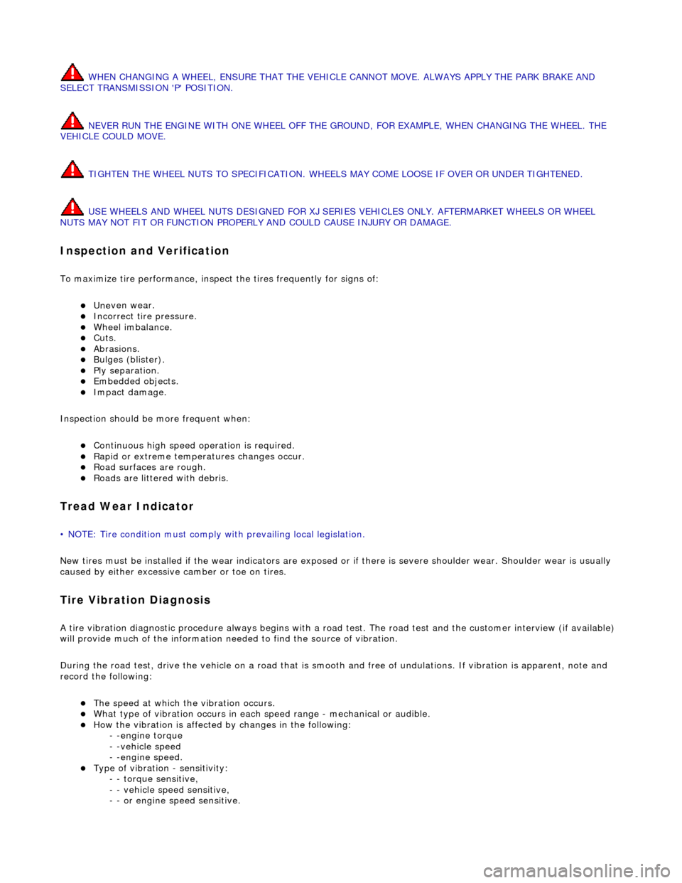
N CHANGING A WHEEL, ENSURE THAT THE VEHICLE CANNOT MOVE. ALWAYS APPLY THE PARK BRAKE AND
SELECT TRANSMISSION 'P' POSITION.
NEVER RUN THE ENGINE WITH ONE WHEEL OFF THE GROUND, FOR EXAMPLE, WHEN CHANGING THE WHEEL. THE
VEHICLE COULD MOVE.
TIGHTEN THE WHEEL NUTS TO SPECIFICATION. WHEELS MAY COME LOOSE IF OVER OR UNDER TIGHTENED.
USE WHEELS AND WHEEL NUTS DESI GNED FOR XJ SERIES VEHICLES ONLY. AFTERMARKET WHEELS OR WHEEL
NUTS MAY NOT FIT OR FUNCTION PROPERLY AND COULD CAUSE INJURY OR DAMAGE.
In
spection and Verification
To maximize ti
re performance, inspec
t the tires frequently for signs of:
Unev
en wear.
Incorrect
ti
re pressure.
Wh
ee
l imbalance.
Cuts. Abrasi
ons.
B
u
lges (blister).
Ply s
e
paration.
Embedded objects. Impact damage.
Inspe c
tion should be
more frequent when:
Continuo
us high speed op
eration is required.
Ra
pid or extreme temperatures changes occur.
R
o
ad surfaces are rough.
Roads ar
e littered
with debris.
Tread W
e
ar Indicator
•
NO
TE: Tire condition must comply with prevailing local legislation.
New tires must be installed if the wear in dicators are exposed or if there is severe shoulder wear. Shoulder wear is usually
caused by either excessive camber or toe on tires.
T i
re Vibration Diagnosis
A
tir
e vibration diagnostic procedure always
begins with a road test. The road test and the custom er interview (if available)
will provide much of the information need ed to find the source of vibration.
During the road test, drive the vehicle on a road that is smooth and free of undulations. If vibration is apparent, note and
record the following:
The s p
eed at which the vibration occurs.
W
h
at type of vibration occurs in each
speed range - mechanical or audible.
How the vibrati
on is affected
by changes in the following:
- -engine torque
- -vehicle speed
- -engine speed.
Type of v i
bration - sensitivity:
- - torque sensitive,
- - vehicle speed sensitive,
- - or engine speed sensitive.
Page 267 of 2490
The
following explanations will help isolate the source of vibration.
Torque Sensitive
This
means that the condition can be impr
oved or made worse by accelerating, dece lerating, coasting, maintaining a steady
vehicle speed, or applying engine torque.
Ve
hicle Speed Sensitive
This means th
at the vibration al
ways occurs at the same vehicle speed and is not affected by engine torque, engine speed
or gear selection.
Engine Speed Sensit
ive
This means th
at the vibration
occurs at varying vehicle spee ds when a different gear is selected. It can sometimes be
isolated by increasing or decreasing engine speed with the tran smission in neutral or by stall testing with the transmission in
gear. If the condition is engine speed sensitive, the cause is probably not related to tires.
If the road test indicates that there is tire wine, but no shake or vibration, the noise originates with the contact between th e
tire and the road surface.
A thumping noise usually means that the tire is flat or has soft spots making a noise as they slap the roadway. Tire whine
can be distinguished from axle no ise, as tire whine remains the same over a range of speeds.
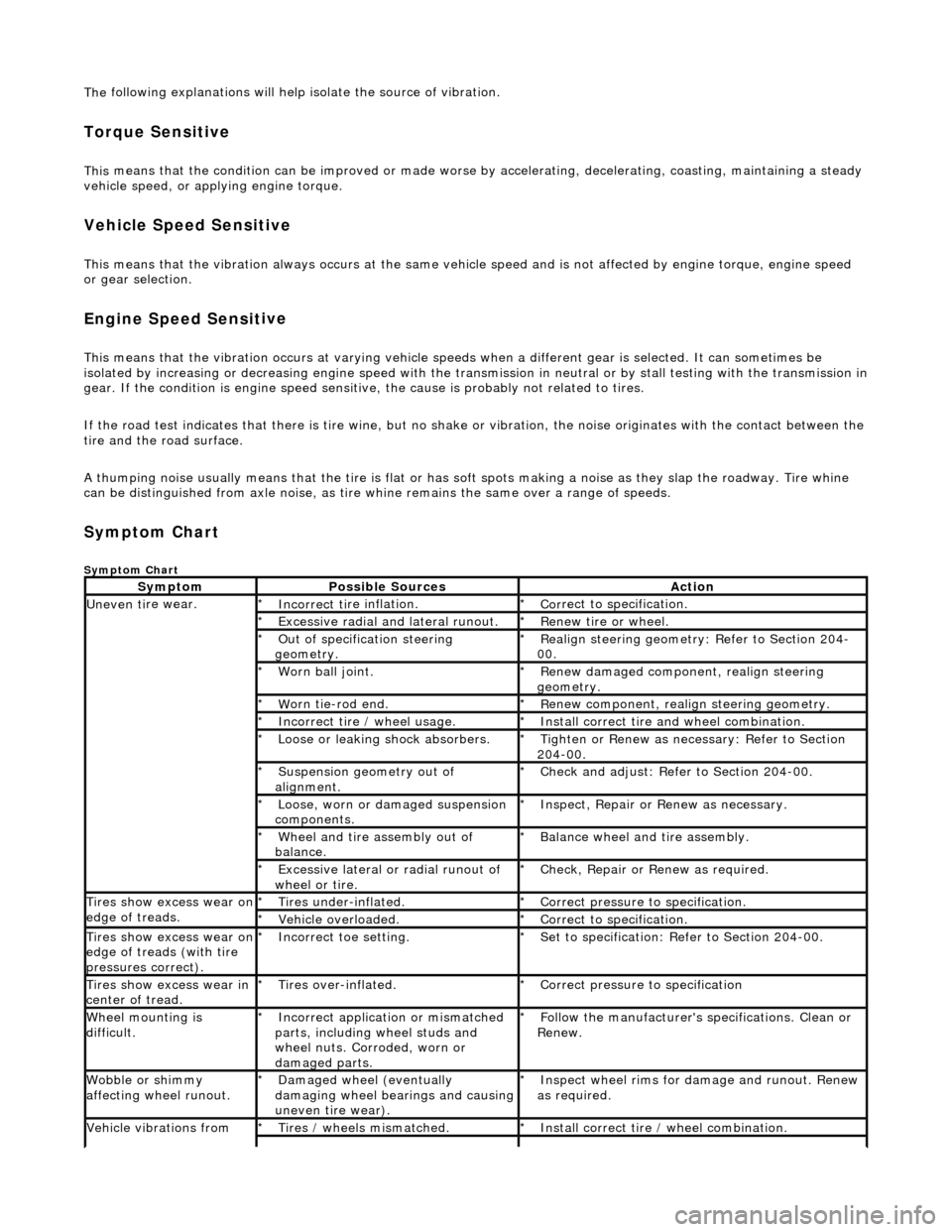
Sym
ptom Chart
Sy
mptom Chart
Sy
mptom
Possib
le Sources
Acti
on
Uneven ti
re wear.
Incorrect ti
re inflation.
*
Cor
rect to specification.
*
Exce
ssive radial an
d lateral runout.
*
Renew tire
or wheel.
*
O
ut of specification steering
geometry.
*
R
ealign steering geometry: Refer to Section 204-
00.
*
W
orn ball joint.
*
Renew
damaged component, realign steering
geometry.
*
W
orn tie-rod end.
*
R
enew component, realign steering geometry.
*
Incorrect
tire / wheel usage.
*
Inst
all correct tire and wheel combination.
*
Loose or leaki
ng shock absorbers.
*
Tigh
ten or Renew as nece
ssary: Refer to Section
204-00.
*
Suspensi
on geometry out of
alignment.
*
Che
ck and adjust: Refer to Section 204-00.
*
Loose, worn or da mage
d suspension
components.
*
In
spect, Repair or Renew as necessary.
*
Wh
eel and tire assembly out of
balance.
*
Balance wheel an
d tire assembly.
*
Excessive later
al or radial runout of
wheel or tire.
*
Check, Repair o
r
Renew as required.
*
Tire
s show excess wear on
edge of treads.
Ti
res under-inflated.
*
Cor
rect pressure to specification.
*
Vehi
cle overloaded.
*
Cor
rect to specification.
*
Tire
s show excess wear on
edge of treads (with tire
pressures correct).
Incorre
ct toe setting.
*
Se
t to specification: Refer to Section 204-00.
*
Tire
s show excess wear in
center of tread.
Tire
s over-inflated.
*
Cor
rect pressure to specification
*
W
heel mounting is
difficult.
Incorrect app
lication or mismatched
parts, including wheel studs and
wheel nuts. Corroded, worn or
damaged parts.
*
Fol
low the manufacturer's specifications. Clean or
Renew.
*
Wobble or sh
immy
affecting wheel runout.
Damaged wh
eel (eventually
damaging wheel bearings and causing
uneven tire wear).
*
Inspect wheel rims for
damage and runout. Renew
as required.
*
Vehicle vibrations from
Tire
s / wheels mismatched.
*
Inst
all correct tire / wheel combination.
*