engine JAGUAR XF 2009 1.G AJ133 5.0L Engine Manual
[x] Cancel search | Manufacturer: JAGUAR, Model Year: 2009, Model line: XF, Model: JAGUAR XF 2009 1.GPages: 36, PDF Size: 0.38 MB
Page 12 of 36

3-10
04/14/2009 NP10-V8JLR: AJ133 5.0-Liter DFI V8 Engine
Technical Training
Relays
Engine Management System
RELAYS
Main Relay
The main Engine Management System (EMS) relay is
not a main power input; it is used to initiate the power-up
and power-down routines within the ECM.
This input comes from the engine junction box (EJB).
When the ignition is turned on 12V is applied to the igni-
tion sense input. The ECM then starts its power-up rou-
tines and turns on the ECM main relay, the main power
to the ECM and its associated system components.
When the ignition is turned OFF, the ECM will maintain
its powered-up state for several seconds (or up to 20
minutes in extreme cases when cooling fans are
required) while it initiates its power-down routine and,
on completion, will turn off the ECM main relay.
The main relay is located in the EJB. The operation of
the main relay is controlled by the ECM, which provides
a ground path for the main relay coil, energizing the
relay and closing the relay contacts.
The main relay supplies battery voltage to the following
engine sensors and actuators:
• Throttle position (TP) sensor (through ECM)
• Fuel injectors
• Ignition coils
• Coil capacitor
• CPS solenoids
• All heated oxygen sensors
• Evaporative emission (EVAP) canister purge valve
• Diagnostic Monitoring of Tank Leakage (DMTL)
Failure Modes
• Relay drive open circuit
• Short circuit to battery voltage or ground
• Component failure
Failure Symptoms
• Engine will not start
Starter Relay
The starter motor relay is located in the EJB. Operation
of the starter motor relay is controlled by the ECM,
which provides a ground path for the relay coil, energiz-
ing the relay and closing the relay contacts. When the
relay contacts are closed, battery voltage is supplied,
through the starter motor relay, to the starter module
solenoid coil.
The starter solenoid is energized and connects the starter
motor with a direct battery feed to operate the starter
motor.
Once the engine has started, the ECM removes the
starter motor relay ground, opening the relay contacts
and terminating the battery feed to the starter solenoid,
which in turn stops the operation of the starter motor.
NOTE:
Diagnose using Jaguar Land Rover approved
diagnostic equipment.
Page 13 of 36
Technical Training
NP10-V8JLR: AJ133 5.0-Liter DFI V8 Engine 04/14/2009
3-11
Engine Management System
Crankshaft Position Sensor
CRANKSHAFT POSITION SENSOR
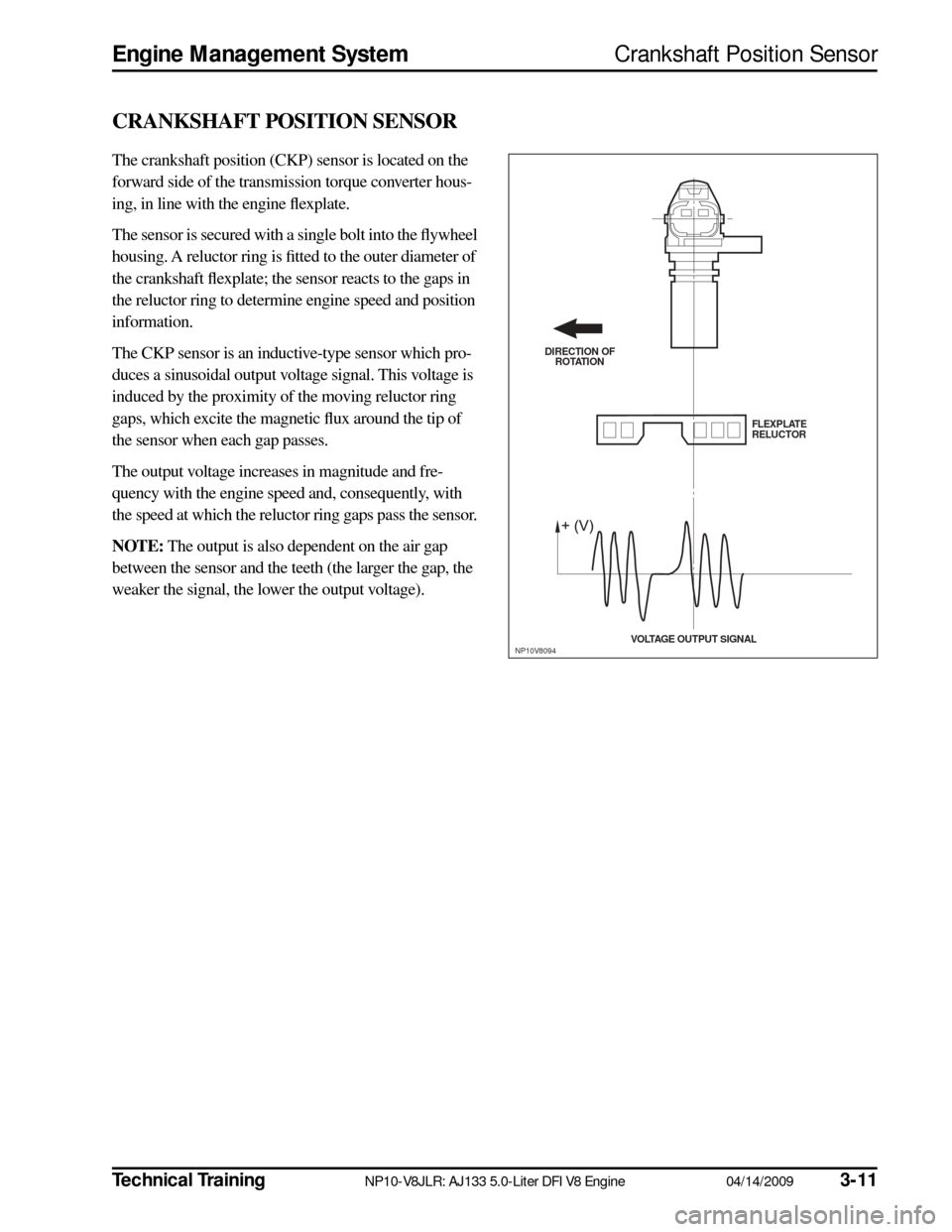
The crankshaft position (CKP) sensor is located on the
forward side of the transmission torque converter hous-
ing, in line with the engine flexplate.
The sensor is secured with a single bolt into the flywheel
housing. A reluctor ring is fitted to the outer diameter of
the crankshaft flexplate; the sensor reacts to the gaps in
the reluctor ring to determine engine speed and position
information.
The CKP sensor is an inductive-type sensor which pro-
duces a sinusoidal output voltage signal. This voltage is
induced by the proximity of the moving reluctor ring
gaps, which excite the magnetic flux around the tip of
the sensor when each gap passes.
The output voltage increases in magnitude and fre-
quency with the engine speed and, consequently, with
the speed at which the reluctor ring gaps pass the sensor.
NOTE:
The output is also dependent on the air gap
between the sensor and the teeth (the larger the gap, the
weaker the signal, the lower the output voltage).
DIRECTION OF ROTATION
FLEXPLATE
RELUCTOR
VOLTAGE OUTPUT S IGNAL
NP10V8094
Page 14 of 36
3-12
04/14/2009 NP10-V8JLR: AJ133 5.0-Liter DFI V8 Engine
Technical Training
Crankshaft Position Sensor
Engine Management System
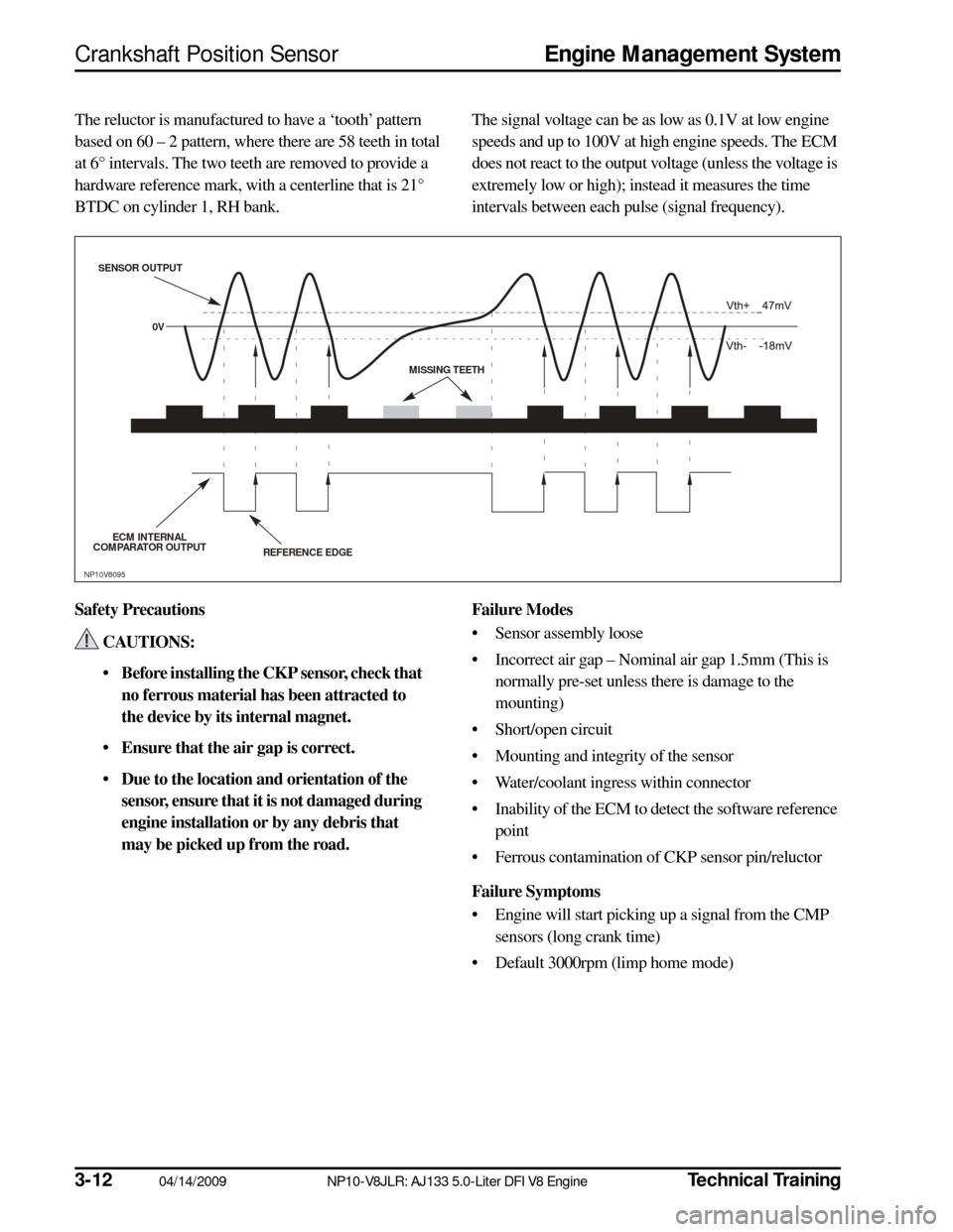
The reluctor is manufactured to have a ‘tooth’ pattern
based on 60 – 2 pattern, where there are 58 teeth in total
at 6° intervals. The two teeth are removed to provide a
hardware reference mark, with a centerline that is 21°
BTDC on cylinder 1, RH bank. The signal voltage can be as low as 0.1V at low engine
speeds and up to 100V at high engine speeds. The ECM
does not react to the output voltage (unless the voltage is
extremely low or high); instead it measures the time
intervals between each pulse (signal frequency).
Safety Precautions CAUTIONS:
• Before installing the CKP sensor, check that no ferrous material has been attracted to
the device by its internal magnet.
• Ensure that the air gap is correct.
• Due to the location and orientation of the sensor, ensure that it is not damaged during
engine installation or by any debris that
may be picked up from the road. Failure Modes
• Sensor assembly loose
• Incorrect air gap – Nominal air gap 1.5mm (This is normally pre-set unless there is damage to the
mounting)
• Short/open circuit
• Mounting and integrity of the sensor
• Water/coolant ingress within connector
• Inability of the ECM to detect the software reference point
• Ferrous contamination of CKP sensor pin/reluctor
Failure Symptoms
• Engine will start picking up a signal from the CMP sensors (long crank time)
• Default 3000rpm (limp home mode)
REFERENCE EDGE
S
ENS OR OUTPUT
ECM INTERNAL
COMPARATOR OUTPUT 0V
MISSING TEETH
NP10V8095
Page 15 of 36
Technical Training
NP10-V8JLR: AJ133 5.0-Liter DFI V8 Engine 04/14/2009
3-13
Engine Management System
Camshaft Position Sensor
CAMSHAFT POSITION SENSOR
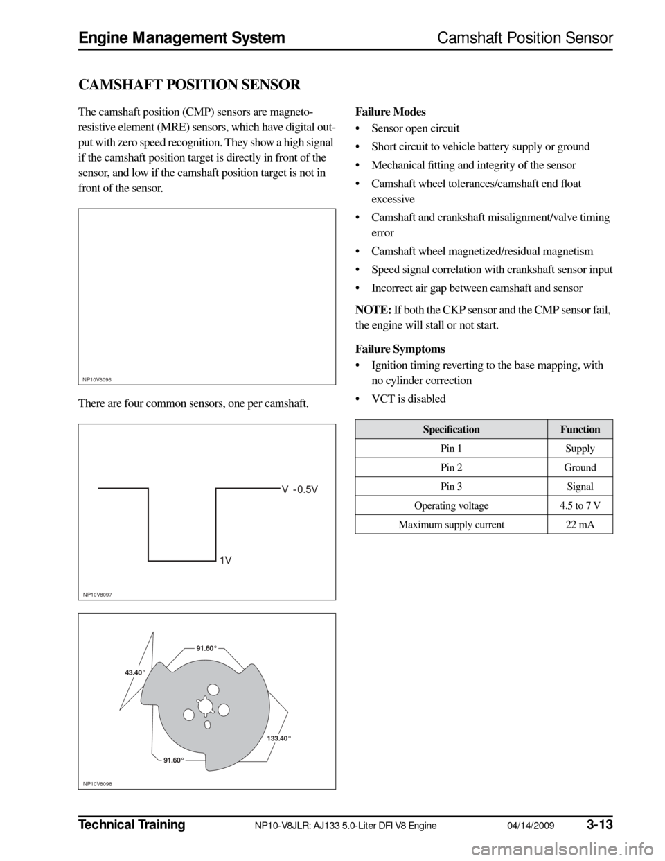
The camshaft position (CMP) sensors are magneto-
resistive element (MRE) sensors, which have digital out-
put with zero speed recognition. They show a high signal
if the camshaft position target is directly in front of the
sensor, and low if the camshaft position target is not in
front of the sensor.
There are four common sensors, one per camshaft.
Failure Modes
• Sensor open circuit
• Short circuit to vehicle battery supply or ground
• Mechanical fitting and integrity of the sensor
• Camshaft wheel tolerances/camshaft end float excessive
• Camshaft and crankshaft misalignment/valve timing error
• Camshaft wheel magnetized/residual magnetism
• Speed signal correlation with crankshaft sensor input
• Incorrect air gap between camshaft and sensor
NOTE:
If both the CKP sensor and the CMP sensor fail,
the engine will stall or not start.
Failure Symptoms
• Ignition timing reverting to the base mapping, with no cylinder correction
• VCT is disabled
NP10V8096
NP10V8097
NP10V8098
43.40°43.40°43.40° 91.60°
91.60°
133.40°133.40°
91.60°
133.40°
91.60°
91.60°91.60°
Specification
Function
Pin 1 Supply
Pin 2 Ground
Pin 3 Signal
Operating voltage 4.5 to 7 V
Maximum supply current 22 mA
Page 16 of 36
3-14
04/14/2009 NP10-V8JLR: AJ133 5.0-Liter DFI V8 Engine
Technical Training
Engine Coolant Temperature Sensor
Engine Management System
ENGINE COOLANT TEMPERATURE SENSOR
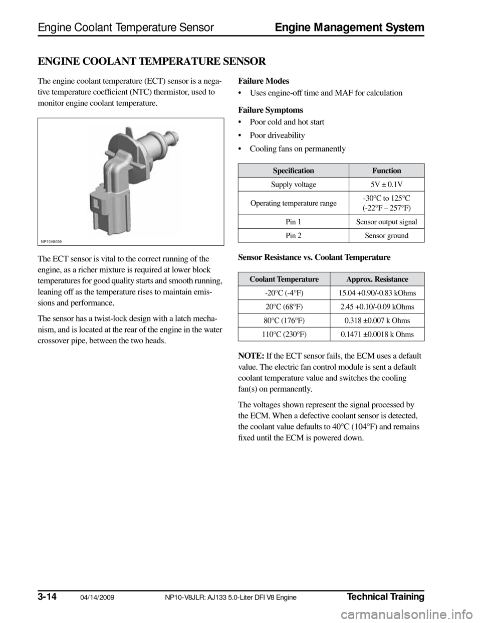
The engine coolant temperature (ECT) sensor is a nega-
tive temperature coefficient (NTC) thermistor, used to
monitor engine coolant temperature.
The ECT sensor is vital to the correct running of the
engine, as a richer mixture is required at lower block
temperatures for good quality starts and smooth running,
leaning off as the temperature rises to maintain emis-
sions and performance.
The sensor has a twist-lock design with a latch mecha-
nism, and is located at the rear of the engine in the water
crossover pipe, between the two heads.
Failure Modes
• Uses engine-off time and MAF for calculation
Failure Symptoms
• Poor cold and hot start
• Poor driveability
• Cooling fans on permanently
Sensor Resistance vs. Coolant Temperature
NOTE:
If the ECT sensor fails, the ECM uses a default
value. The electric fan control module is sent a default
coolant temperature value and switches the cooling
fan(s) on permanently.
The voltages shown represent the signal processed by
the ECM. When a defective coolant sensor is detected,
the coolant value defaults to 40°C (104°F) and remains
fixed until the ECM is powered down.
NP10V8099
Specification
Function
Supply voltage 5V ± 0.1V
Operating temperature range -30°C to 125°C
(-22°F – 257°F)
Pin 1 Sensor output signal
Pin 2 Sensor ground
Coolant Temperature
Approx. Resistance
-20°C (-4°F) 15.04 +0.90/-0.83 kOhms 20°C (68°F) 2.45 +0.10/-0.09 kOhms
80°C (176°F) 0.318 ±0.007 k Ohms
110°C (230°F) 0.1471 ±0.0018 k Ohms
Page 17 of 36
Technical Training
NP10-V8JLR: AJ133 5.0-Liter DFI V8 Engine 04/14/2009
3-15
Engine Management System
Knock Sensors
KNOCK SENSORS
The ECM uses active knock control, which serves to
prevent engine damaging pre-ignition or detonation
under all operating conditions, enabling the engine to
operate without additional safety margins.
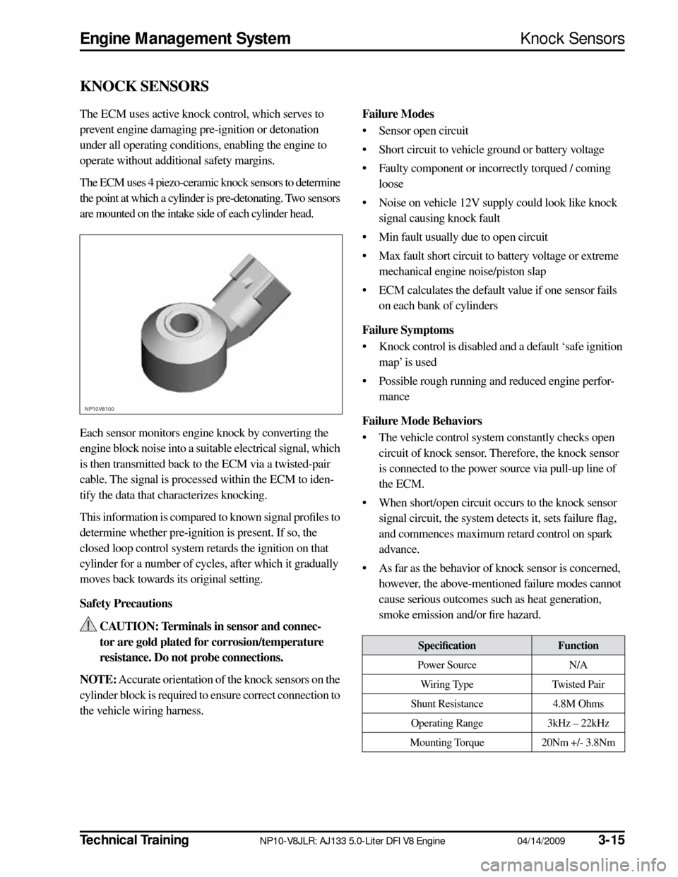
The ECM uses 4 piezo-ceramic knock sensors to determine
the point at which a cylinder is pre-detonating. Two sensors
are mounted on the intake side of each cylinder head.
Each sensor monitors engine knock by converting the
engine block noise into a suitable electrical signal, which
is then transmitted back to the ECM via a twisted-pair
cable. The signal is processed within the ECM to iden-
tify the data that characterizes knocking.
This information is compared to known signal profiles to
determine whether pre-ignition is present. If so, the
closed loop control system retards the ignition on that
cylinder for a number of cycles, after which it gradually
moves back towards its original setting.
Safety Precautions CAUTION: Terminals in sensor and connec-
tor are gold plated for corrosion/temperature
resistance. Do not probe connections.
NOTE:
Accurate orientation of the knock sensors on the
cylinder block is required to ensure correct connection to
the vehicle wiring harness.
Failure Modes
• Sensor open circuit
• Short circuit to vehicle ground or battery voltage
• Faulty component or incorrectly torqued / coming loose
• Noise on vehicle 12V supply could look like knock signal causing knock fault
• Min fault usually due to open circuit
• Max fault short circuit to battery voltage or extreme mechanical engine noise/piston slap
• ECM calculates the default value if one sensor fails on each bank of cylinders
Failure Symptoms
• Knock control is disabled and a default ‘safe ignition map’ is used
• Possible rough running and reduced engine perfor- mance
Failure Mode Behaviors
• The vehicle control system constantly checks open circuit of knock sensor. Therefore, the knock sensor
is connected to the power source via pull-up line of
the ECM.
• When short/open circuit occurs to the knock sensor signal circuit, the system detects it, sets failure flag,
and commences maximum retard control on spark
advance.
• As far as the behavior of knock sensor is concerned, however, the above-mentioned failure modes cannot
cause serious outcomes such as heat generation,
smoke emission and/or fire hazard.
NP10V8100
Specification
Function
Power Source N/A
Wiring Type Twisted Pair
Shunt Resistance 4.8M Ohms
Operating Range 3kHz – 22kHz
Mounting Torque 20Nm +/- 3.8Nm
Page 18 of 36
3-16
04/14/2009 NP10-V8JLR: AJ133 5.0-Liter DFI V8 Engine
Technical Training
Manifold Absolute Pressure Sensor
Engine Management System
MANIFOLD ABSOLUTE PRESSURE SENSOR
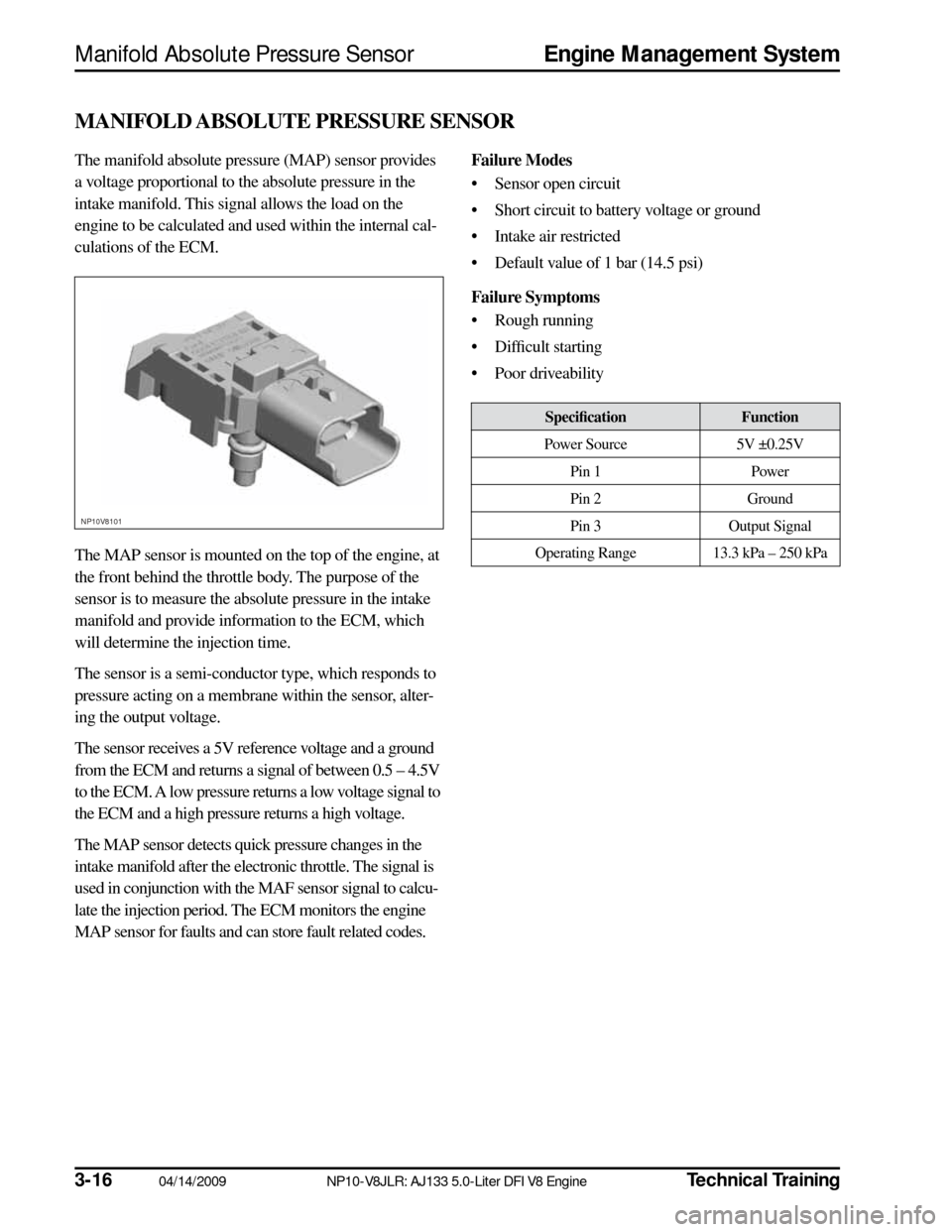
The manifold absolute pressure (MAP) sensor provides
a voltage proportional to the absolute pressure in the
intake manifold. This signal allows the load on the
engine to be calculated and used within the internal cal-
culations of the ECM.
The MAP sensor is mounted on the top of the engine, at
the front behind the throttle body. The purpose of the
sensor is to measure the absolute pressure in the intake
manifold and provide information to the ECM, which
will determine the injection time.
The sensor is a semi-conductor type, which responds to
pressure acting on a membrane within the sensor, alter-
ing the output voltage.
The sensor receives a 5V reference voltage and a ground
from the ECM and returns a signal of between 0.5 – 4.5V
to the ECM. A low pressure returns a low voltage signal to
the ECM and a high pressure returns a high voltage.
The MAP sensor detects quick pressure changes in the
intake manifold after the electronic throttle. The signal is
used in conjunction with the MAF sensor signal to calcu-
late the injection period. The ECM monitors the engine
MAP sensor for faults and can store fault related codes.
Failure Modes
• Sensor open circuit
• Short circuit to battery voltage or ground
• Intake air restricted
• Default value of 1 bar (14.5 psi)
Failure Symptoms
• Rough running
• Difficult starting
• Poor driveability
NP10V8101
Specification
Function
Power Source 5V ±0.25V
Pin 1 Power
Pin 2 Ground
Pin 3 Output Signal
Operating Range 13.3 kPa – 250 kPa
Page 19 of 36

Technical Training
NP10-V8JLR: AJ133 5.0-Liter DFI V8 Engine 04/14/2009
3-17
Engine Management System
Mass Air Flow Sensor
MASS AIR FLOW SENSOR
Mass air flow is determined by the cooling effect of
intake air passing over a ‘hot film’ element contained
within the device. The higher the air flow the greater the
cooling effect and the lower the electrical resistance of
the ‘hot film’ element. The ECM then uses this analog
signal from the mass air flow (MAF) sensor to calculate
the air mass flowing into the engine.
The measured air mass flow is used in determining the
fuel quantity to be injected in order to maintain the sto-
ichiometric air/fuel mixture required for correct opera-
tion of the engine and exhaust catalysts. Should the
device fail, there is a software backup strategy that will
be activated once a fault has been logged.
The intake air temperature (IAT) sensor is integrated into
the MAF sensor. The IAT sensor is an NTC thermistor,
meaning that the sensor resistance decreases as the sen-
sor temperature increases.
The sensor forms part of a voltage divider chain with an
additional resistor in the ECM. The voltage from this device
changes as the sensor resistance changes, thus relating the
air temperature to the voltage measured by the ECM.
Because the engine requires a twin air intake induction
system, there are two MAF sensors per vehicle.
Safety Precautions CAUTIONS:
• Component should not be dropped or han-dled roughly.
• Ensure that no contamination enters the device.
• Some terminals in MAF and connector are gold-plated for corrosion resistance – DO
NOT probe.
Failure Modes
• Sensor open circuit
• Short circuit to battery voltage or ground
• Contaminated/damaged sensor element
• Air leak after MAF sensor
• Intake air restricted
• Resistance in the harness, causing signal offset
• Damaged sensor element
Failure Symptoms
• During driving the engine rpm might dip (before recovering)
• Difficulty in starting or start/stall
• Poor throttle response/engine performance
• Emissions incorrect
• Lambda control and idle speed control halted
• MAF signal offset
NP10V8102
SpecificationFunction
Supply Voltage 8 – 14V
(rated supply voltage: 14V)
Pin A Output (Vg)
Pin B Ground for Output (Vg)
Pin C Power Source
Pin D IAT Sensor Ground
Pin E IAT Sensor Output
Page 20 of 36
3-1804/14/2009NP10-V8JLR: AJ133 5.0-Liter DFI V8 EngineTechnical Training
Temperature/Manifold Absolute Pressure Sensor Engine Management System
TEMPERATURE AND MANIFOLD ABSOLUTE PRESSURE SENSOR
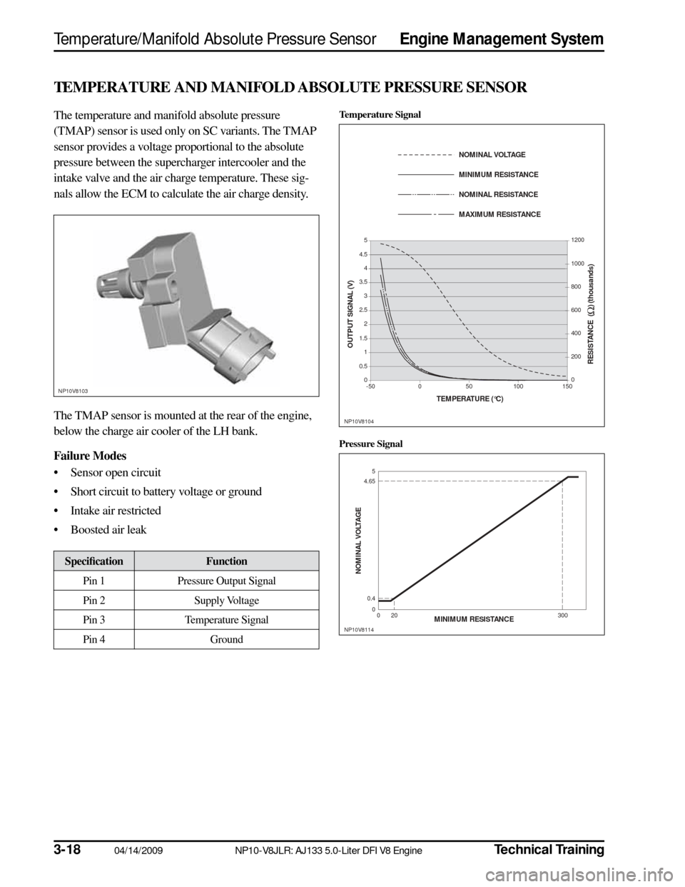
The temperature and manifold absolute pressure
(TMAP) sensor is used only on SC variants. The TMAP
sensor provides a voltage proportional to the absolute
pressure between the supercharger intercooler and the
intake valve and the air charge temperature. These sig-
nals allow the ECM to calculate the air charge density.
The TMAP sensor is mounted at the rear of the engine,
below the charge air cooler of the LH bank.
Failure Modes
• Sensor open circuit
• Short circuit to battery voltage or ground
• Intake air restricted
• Boosted air leak
SpecificationFunction
Pin 1 Pressure Output Signal
Pin 2 Supply Voltage
Pin 3 Temperature Signal
Pin 4 Ground
NP10V8103
Temperature Signal
Pressure Signal
TEMPERATURE (°C)
OUTPUT SIGNAL (V)
RES IS TANCE (
Ω) (thous ands)
NP10V8104
5
4.5 4
3.5
3
2.5 2
1.5 1
0
0.5
-50 50 0 1001500 200 400 600
800 1000 1200
NOMINAL VOLTAGE
MINIMUM RES
IS TANCE
NOMINAL RES IS TANCE
MAXIMUM RES IS TANCE
NP10V8114
0
0.4
4.65
5
0 20 300
NOMINAL VOLTAGE
MINIMUM RESIS TANCE
Page 21 of 36

Technical TrainingNP10-V8JLR: AJ133 5.0-Liter DFI V8 Engine04/14/20093-19
Engine Management SystemThrottle Position Sensor
THROTTLE POSITION SENSOR
The engine torque is regulated via an electronic throttle
body (‘drive-by-wire’ system), where an electronic pedal
assembly determines throttle opening.
The throttle position (TP) sensor is mounted in the inte-
grated cover plate on the throttle body assembly. The
throttle body assembly is mounted at the top front of the
engine, in a similar position for both NA and SC variants.
This value is input into the ECM and the throttle is
opened to the correct angle by means of an electric direct
current (DC) motor integrated into the throttle body.
Movement of the motor is achieved by changing the
PWM signal to the DC motor, allowing it to be operated
in both directions.
The dual-output TP sensor in the throttle body is used to
determine the position of the throttle blade and the rate
of change in its angle.
A software strategy within the ECM enables the throttle
position to be calibrated each ignition cycle. When the
ignition is turned ON, the ECM commands the throttle
to open and close fully, thus performing a self-test and
calibration, learning the position of the full closed hard
stop position.Safety Precautions
CAUTION: Terminals in sensor and connec-
tor are gold-plated for corrosion/temperature
resistance – DO NOT probe.
Failure Modes
• Sensor open circuit
• Short circuit to battery voltage or ground
• If signal failure occurs the ECM will enter a limp home mode where the maximum engine speed is
2000 rpm
• Signal offset
• Vacuum leak
Failure Symptoms
• Poor engine running and throttle response
• Limp home mode – maximum 2000 rpm
• Emission control failure
• No closed loop idle speed control
NP10V8105
SpecificationFunction
Supply voltage 5V ± 0.2 V
Supply current Max. 10 mA/1 output
Tolerance – closed position ±150 mV Tolerance – WOT position ±150 mV
Operating temperature range -40°C – 160°C
(-40°F – 320°F)
Pin 1 Throttle motor valve open:
direction +
Pin 2 Throttle motor valve open:
direction –
Pin 3 Position sensor output 2
(Gold)
Pin 4 Ground (Gold)
Pin 5 Position sensor output 1
(Gold)
Pin 6 Position sensor 5V supply
(Gold)