ESP JAGUAR XF 2009 1.G AJ133 5.0L Engine Manual
[x] Cancel search | Manufacturer: JAGUAR, Model Year: 2009, Model line: XF, Model: JAGUAR XF 2009 1.GPages: 36, PDF Size: 0.38 MB
Page 11 of 36

Technical Training
NP10-V8JLR: AJ133 5.0-Liter DFI V8 Engine 04/14/2009
3-9
Engine Management System
Engine Control Module
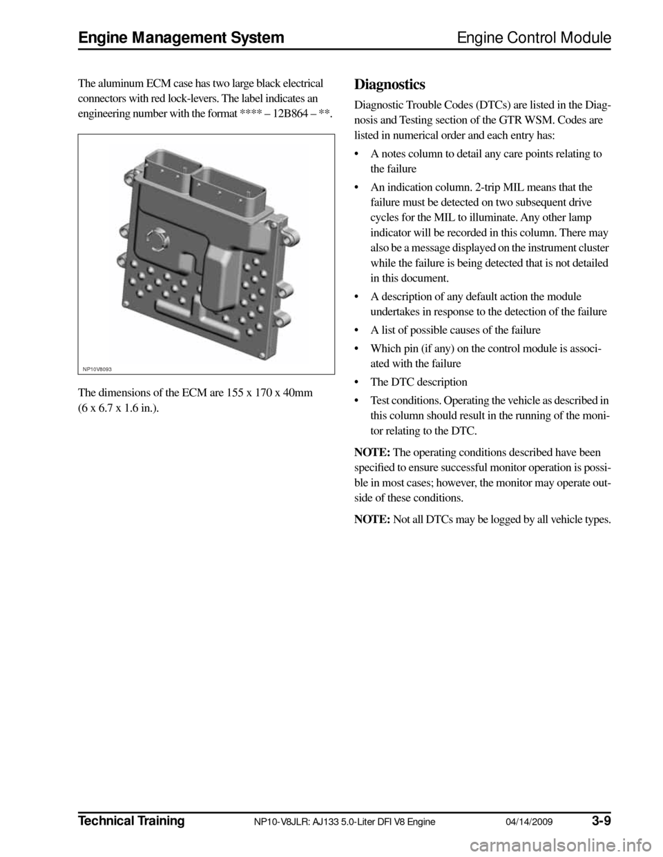
The aluminum ECM case has two large black electrical
connectors with red lock-levers. The label indicates an
engineering number with the format **** – 12B864 – **.
The dimensions of the ECM are 155 x 170 x 40mm
(6 x 6.7 x 1.6 in.). Diagnostics
Diagnostic Trouble Codes (DTCs) are listed in the Diag-
nosis and Testing section of the GTR WSM. Codes are
listed in numerical order and each entry has:
• A notes column to detail any care points relating to the failure
• An indication column. 2-trip MIL means that the failure must be detected on two subsequent drive
cycles for the MIL to illuminate. Any other lamp
indicator will be recorded in this column. There may
also be a message displayed on the instrument cluster
while the failure is being detected that is not detailed
in this document.
• A description of any default action the module undertakes in response to the detection of the failure
• A list of possible causes of the failure
• Which pin (if any) on the control module is associ- ated with the failure
• The DTC description
• Test conditions. Operating the vehicle as described in this column should result in the running of the moni-
tor relating to the DTC.
NOTE:
The operating conditions described have been
specified to ensure successful monitor operation is possi-
ble in most cases; however, the monitor may operate out-
side of these conditions.
NOTE:
Not all DTCs may be logged by all vehicle types.
NP10V8093
Page 18 of 36

3-16
04/14/2009 NP10-V8JLR: AJ133 5.0-Liter DFI V8 Engine
Technical Training
Manifold Absolute Pressure Sensor
Engine Management System
MANIFOLD ABSOLUTE PRESSURE SENSOR
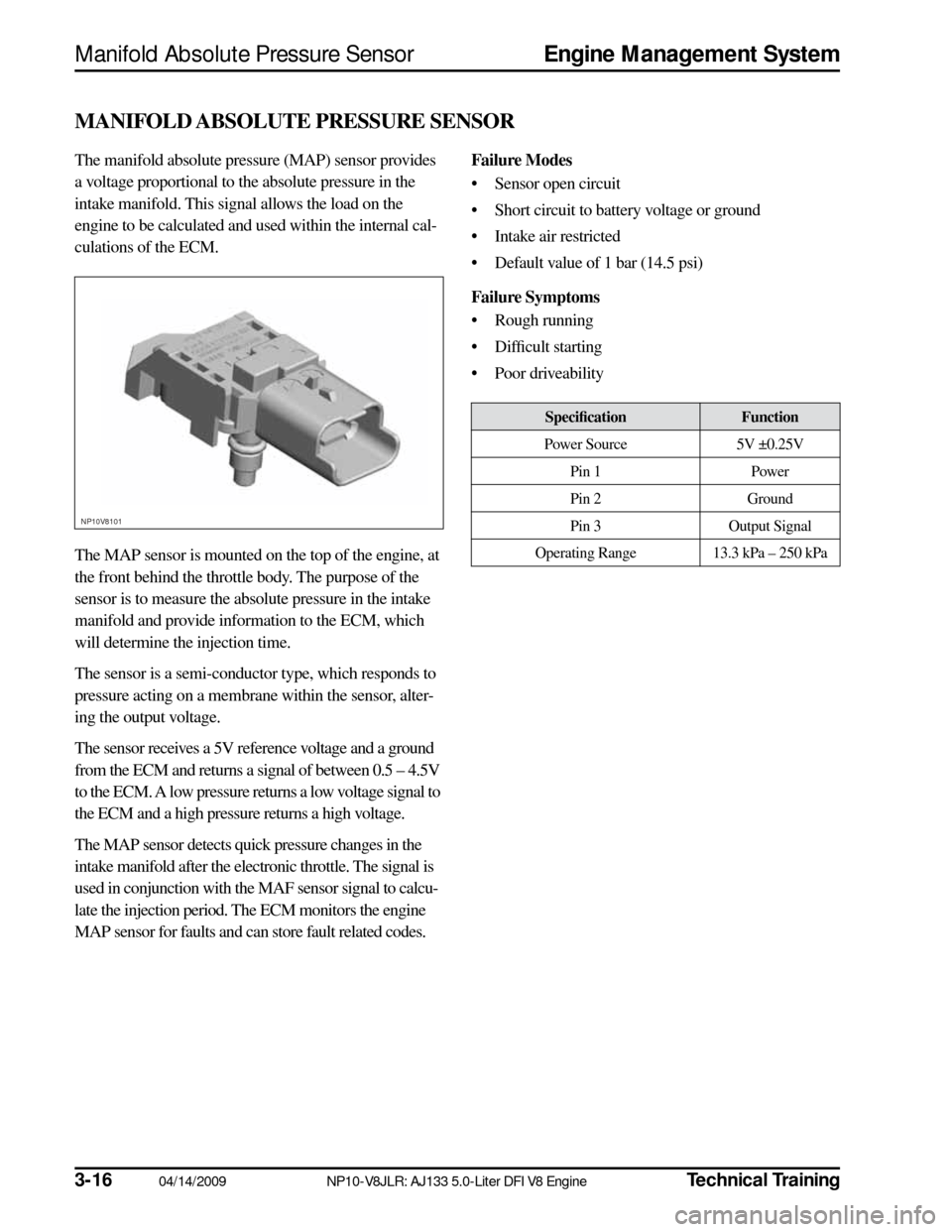
The manifold absolute pressure (MAP) sensor provides
a voltage proportional to the absolute pressure in the
intake manifold. This signal allows the load on the
engine to be calculated and used within the internal cal-
culations of the ECM.
The MAP sensor is mounted on the top of the engine, at
the front behind the throttle body. The purpose of the
sensor is to measure the absolute pressure in the intake
manifold and provide information to the ECM, which
will determine the injection time.
The sensor is a semi-conductor type, which responds to
pressure acting on a membrane within the sensor, alter-
ing the output voltage.
The sensor receives a 5V reference voltage and a ground
from the ECM and returns a signal of between 0.5 – 4.5V
to the ECM. A low pressure returns a low voltage signal to
the ECM and a high pressure returns a high voltage.
The MAP sensor detects quick pressure changes in the
intake manifold after the electronic throttle. The signal is
used in conjunction with the MAF sensor signal to calcu-
late the injection period. The ECM monitors the engine
MAP sensor for faults and can store fault related codes.
Failure Modes
• Sensor open circuit
• Short circuit to battery voltage or ground
• Intake air restricted
• Default value of 1 bar (14.5 psi)
Failure Symptoms
• Rough running
• Difficult starting
• Poor driveability
NP10V8101
Specification
Function
Power Source 5V ±0.25V
Pin 1 Power
Pin 2 Ground
Pin 3 Output Signal
Operating Range 13.3 kPa – 250 kPa
Page 19 of 36

Technical Training
NP10-V8JLR: AJ133 5.0-Liter DFI V8 Engine 04/14/2009
3-17
Engine Management System
Mass Air Flow Sensor
MASS AIR FLOW SENSOR
Mass air flow is determined by the cooling effect of
intake air passing over a ‘hot film’ element contained
within the device. The higher the air flow the greater the
cooling effect and the lower the electrical resistance of
the ‘hot film’ element. The ECM then uses this analog
signal from the mass air flow (MAF) sensor to calculate
the air mass flowing into the engine.
The measured air mass flow is used in determining the
fuel quantity to be injected in order to maintain the sto-
ichiometric air/fuel mixture required for correct opera-
tion of the engine and exhaust catalysts. Should the
device fail, there is a software backup strategy that will
be activated once a fault has been logged.
The intake air temperature (IAT) sensor is integrated into
the MAF sensor. The IAT sensor is an NTC thermistor,
meaning that the sensor resistance decreases as the sen-
sor temperature increases.
The sensor forms part of a voltage divider chain with an
additional resistor in the ECM. The voltage from this device
changes as the sensor resistance changes, thus relating the
air temperature to the voltage measured by the ECM.
Because the engine requires a twin air intake induction
system, there are two MAF sensors per vehicle.
Safety Precautions CAUTIONS:
• Component should not be dropped or han-dled roughly.
• Ensure that no contamination enters the device.
• Some terminals in MAF and connector are gold-plated for corrosion resistance – DO
NOT probe.
Failure Modes
• Sensor open circuit
• Short circuit to battery voltage or ground
• Contaminated/damaged sensor element
• Air leak after MAF sensor
• Intake air restricted
• Resistance in the harness, causing signal offset
• Damaged sensor element
Failure Symptoms
• During driving the engine rpm might dip (before recovering)
• Difficulty in starting or start/stall
• Poor throttle response/engine performance
• Emissions incorrect
• Lambda control and idle speed control halted
• MAF signal offset
NP10V8102
SpecificationFunction
Supply Voltage 8 – 14V
(rated supply voltage: 14V)
Pin A Output (Vg)
Pin B Ground for Output (Vg)
Pin C Power Source
Pin D IAT Sensor Ground
Pin E IAT Sensor Output
Page 21 of 36

Technical TrainingNP10-V8JLR: AJ133 5.0-Liter DFI V8 Engine04/14/20093-19
Engine Management SystemThrottle Position Sensor
THROTTLE POSITION SENSOR
The engine torque is regulated via an electronic throttle
body (‘drive-by-wire’ system), where an electronic pedal
assembly determines throttle opening.
The throttle position (TP) sensor is mounted in the inte-
grated cover plate on the throttle body assembly. The
throttle body assembly is mounted at the top front of the
engine, in a similar position for both NA and SC variants.
This value is input into the ECM and the throttle is
opened to the correct angle by means of an electric direct
current (DC) motor integrated into the throttle body.
Movement of the motor is achieved by changing the
PWM signal to the DC motor, allowing it to be operated
in both directions.
The dual-output TP sensor in the throttle body is used to
determine the position of the throttle blade and the rate
of change in its angle.
A software strategy within the ECM enables the throttle
position to be calibrated each ignition cycle. When the
ignition is turned ON, the ECM commands the throttle
to open and close fully, thus performing a self-test and
calibration, learning the position of the full closed hard
stop position.Safety Precautions
CAUTION: Terminals in sensor and connec-
tor are gold-plated for corrosion/temperature
resistance – DO NOT probe.
Failure Modes
• Sensor open circuit
• Short circuit to battery voltage or ground
• If signal failure occurs the ECM will enter a limp home mode where the maximum engine speed is
2000 rpm
• Signal offset
• Vacuum leak
Failure Symptoms
• Poor engine running and throttle response
• Limp home mode – maximum 2000 rpm
• Emission control failure
• No closed loop idle speed control
NP10V8105
SpecificationFunction
Supply voltage 5V ± 0.2 V
Supply current Max. 10 mA/1 output
Tolerance – closed position ±150 mV Tolerance – WOT position ±150 mV
Operating temperature range -40°C – 160°C
(-40°F – 320°F)
Pin 1 Throttle motor valve open:
direction +
Pin 2 Throttle motor valve open:
direction –
Pin 3 Position sensor output 2
(Gold)
Pin 4 Ground (Gold)
Pin 5 Position sensor output 1
(Gold)
Pin 6 Position sensor 5V supply
(Gold)
Page 25 of 36

Technical TrainingNP10-V8JLR: AJ133 5.0-Liter DFI V8 Engine04/14/20093-23
Engine Management SystemHeated Oxygen Sensors
Upstream Universal Heated Exhaust Gas Oxygen Sensors
In order to improve the control of the air : fuel ratio
(AFR) under varying engine conditions, a linear or ‘uni-
versal’ heated exhaust gas oxygen (UHEGO) sensor is
used in the upstream location. The UHEGO has a vary-
ing current response to changes in the exhaust gas oxy-
gen content.
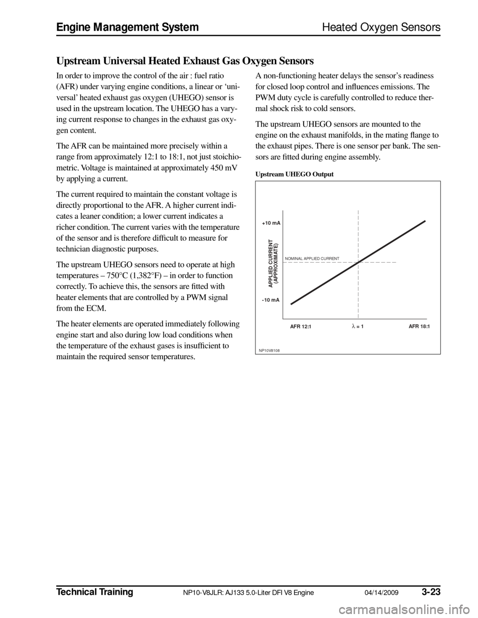
The AFR can be maintained more precisely within a
range from approximately 12:1 to 18:1, not just stoichio-
metric. Voltage is maintained at approximately 450 mV
by applying a current.
The current required to maintain the constant voltage is
directly proportional to the AFR. A higher current indi-
cates a leaner condition; a lower current indicates a
richer condition. The current varies with the temperature
of the sensor and is therefore difficult to measure for
technician diagnostic purposes.
The upstream UHEGO sensors need to operate at high
temperatures – 750°C (1,382°F) – in order to function
correctly. To achieve this, the sensors are fitted with
heater elements that are controlled by a PWM signal
from the ECM.
The heater elements are operated immediately following
engine start and also during low load conditions when
the temperature of the exhaust gases is insufficient to
maintain the required sensor temperatures.A non-functioning heater delays the sensor’s readiness
for closed loop control and influences emissions. The
PWM duty cycle is carefully controlled to reduce ther-
mal shock risk to cold sensors.
The upstream UHEGO sensors are mounted to the
engine on the exhaust manifolds, in the mating flange to
the exhaust pipes. There is one sensor per bank. The sen-
sors are fitted during engine assembly.
Upstream UHEGO Output
NP10V8108
+10 mA
NOMINAL APPLIED CURRENT
-10 mA
AFR 12:1
APPLIED CURRENT(APPROXIMATE)
AFR 18:1λ = 1