cruise control JAGUAR XFR 2010 1.G Workshop Manual
[x] Cancel search | Manufacturer: JAGUAR, Model Year: 2010, Model line: XFR, Model: JAGUAR XFR 2010 1.GPages: 3039, PDF Size: 58.49 MB
Page 161 of 3039

DTC Description Possible Causes Action system, complete a CAN network integrity test.
Refer to the electrical circuit diagrams and check
the CAN network U0103-00
Lost communication
With Gear Shift Module
A - No sub type
information
Gear shift control module /
system fault
Wiring harness fault
Check the Gear Shift Control Module for related
DTCs and refer to the relevant DTC index
Refer to the electrical circuit diagrams and check
the power and ground connections to the module.
Using the manufacturer approved diagnostic
system, complete a CAN network integrity test.
Refer to the electrical circuit diagrams and check
the CAN network U0104-00 Lost communication
Speed control module /
Check the Speed Control Module for related DTCs With Cruise Control Module A - No sub type system fault and refer to the relevant DTC index information Wiring harness fault Refer to the electrical circuit diagrams and check the power and ground connections to the module. Using the manufacturer approved diagnostic system, complete a CAN network integrity test. Refer to the electrical circuit diagrams and check the CAN network U0121-00
Lost communication
with Anti-Lock Braking
System (ABS) Control
Module - No sub type
information
Anti-Lock Braking System
control module / system
fault
Wiring harness fault
Check the Anti-Lock Braking System Control
Module for related DTCs and refer to the relevant
DTC index
Refer to the electrical circuit diagrams and check
the power and ground connections to the module.
Using the manufacturer approved diagnostic
system, complete a CAN network integrity test.
Refer to the electrical circuit diagrams and check
the CAN network U0155-00
Lost Communication
With Instrument Panel
Cluster (IPC) Control
Module - No sub type
information
Instrument Cluster /
system fault
Wiring harness fault
Check the Instrument Cluster for related DTCs
and refer to the relevant DTC index
Refer to the electrical circuit diagrams and check
the power and ground connections to the module.
Using the manufacturer approved diagnostic
system, complete a CAN network integrity test.
Refer to the electrical circuit diagrams and check
the CAN network U0300-00
Internal Control Module
Software
Incompatibility - No sub
type information
Car configuration file
stored in Park Brake
Module does not match the
master car configuration
file
Master car configuration
file not being transmitted
by master control module
Check all control modules for related DTCs and
refer to the relevant DTC index
Check the components installed on the vehicle
were installed by the factory or a dealer
Install the original components or a new one as
required U0401-00
Invalid Data Received
From ECM/PCM - No sub
type information
Invalid message from the
Engine Control Module
Check the Engine Control Module for related DTCs
and refer to the relevant DTC index U0404-00
Invalid Data Received
From Gear Shift Control
Module A - No sub type
information
Invalid message from the
gear shift control module
Check the Gear Shift Control Module for related
DTCs and refer to the relevant DTC index U0415-00
Invalid Data Received
From Anti-Lock Braking
System (ABS) Control
Module - No sub type
information
Invalid message from the
anti-lock Braking system
module
NOTE: This DTC may be stored even though no fault
condition is present and should be ignored unless the
customer has reported a electronic park brake concern.
Clear the DTC and retest. Verify the customer concern
prior to diagnosis
Check the Anti-Lock Braking System Control
Module for related DTCs and refer to the relevant
DTC index U0422-00
Invalid data received
from Central Junction
Box - No sub type
information
Invalid message from the
Central Junction Box
Check the Central Junction Box for related DTCs
and refer to the relevant DTC index
Page 162 of 3039
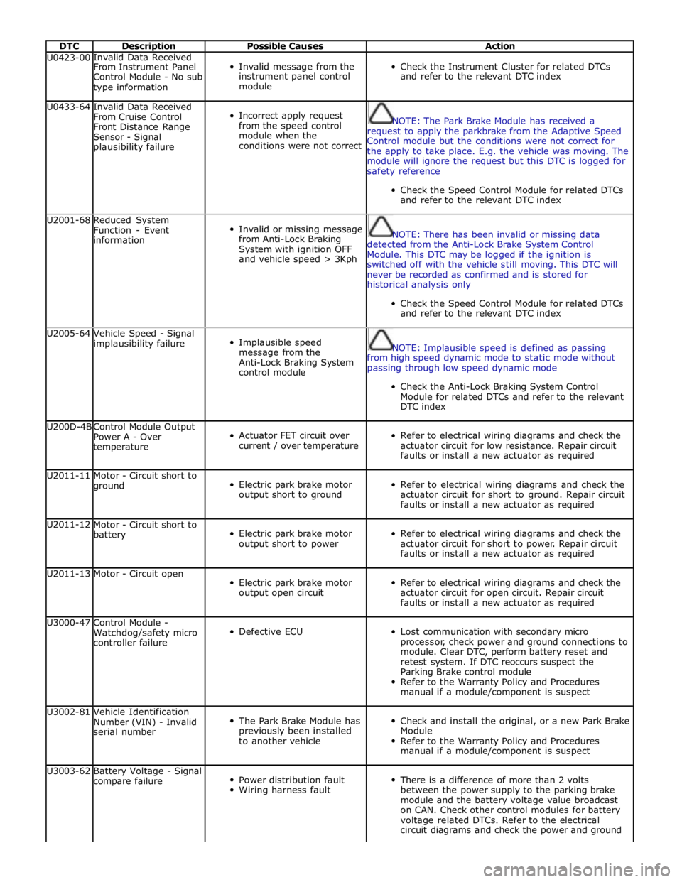
DTC Description Possible Causes Action U0423-00 Invalid Data Received
Invalid message from the
Check the Instrument Cluster for related DTCs From Instrument Panel Control Module - No sub instrument panel control and refer to the relevant DTC index type information module U0433-64
Invalid Data Received
From Cruise Control
Front Distance Range
Sensor - Signal
plausibility failure
Incorrect apply request
from the speed control
module when the
conditions were not correct
NOTE: The Park Brake Module has received a
request to apply the parkbrake from the Adaptive Speed
Control module but the conditions were not correct for
the apply to take place. E.g. the vehicle was moving. The
module will ignore the request but this DTC is logged for
safety reference
Check the Speed Control Module for related DTCs
and refer to the relevant DTC index U2001-68
Reduced System
Function - Event
information
Invalid or missing message
from Anti-Lock Braking
System with ignition OFF
and vehicle speed > 3Kph
NOTE: There has been invalid or missing data
detected from the Anti-Lock Brake System Control
Module. This DTC may be logged if the ignition is
switched off with the vehicle still moving. This DTC will
never be recorded as confirmed and is stored for
historical analysis only
Check the Speed Control Module for related DTCs
and refer to the relevant DTC index U2005-64
Vehicle Speed - Signal
implausibility failure
Implausible speed
message from the
Anti-Lock Braking System
control module
NOTE: Implausible speed is defined as passing
from high speed dynamic mode to static mode without
passing through low speed dynamic mode
Check the Anti-Lock Braking System Control
Module for related DTCs and refer to the relevant
DTC index U200D-4B
Control Module Output
Power A - Over
temperature
Actuator FET circuit over
current / over temperature
Refer to electrical wiring diagrams and check the
actuator circuit for low resistance. Repair circuit
faults or install a new actuator as required U2011-11
Motor - Circuit short to
ground
Electric park brake motor
output short to ground
Refer to electrical wiring diagrams and check the
actuator circuit for short to ground. Repair circuit
faults or install a new actuator as required U2011-12
Motor - Circuit short to
battery
Electric park brake motor
output short to power
Refer to electrical wiring diagrams and check the
actuator circuit for short to power. Repair circuit
faults or install a new actuator as required U2011-13 Motor - Circuit open
Electric park brake motor
output open circuit
Refer to electrical wiring diagrams and check the
actuator circuit for open circuit. Repair circuit
faults or install a new actuator as required U3000-47
Control Module -
Watchdog/safety micro
controller failure
Defective ECU
Lost communication with secondary micro
processor, check power and ground connections to
module. Clear DTC, perform battery reset and
retest system. If DTC reoccurs suspect the
Parking Brake control module
Refer to the Warranty Policy and Procedures
manual if a module/component is suspect U3002-81
Vehicle Identification
Number (VIN) - Invalid
serial number
The Park Brake Module has
previously been installed
to another vehicle
Check and install the original, or a new Park Brake
Module
Refer to the Warranty Policy and Procedures
manual if a module/component is suspect U3003-62
Battery Voltage - Signal
compare failure
Power distribution fault
Wiring harness fault
There is a difference of more than 2 volts
between the power supply to the parking brake
module and the battery voltage value broadcast
on CAN. Check other control modules for battery
voltage related DTCs. Refer to the electrical
circuit diagrams and check the power and ground
Page 164 of 3039
Published: 18-Apr-2014
General Information - Diagnostic Trouble Code (DTC) Index V8 S/C 5.0L
Petrol, DTC: Engine Control Module (ECM)
Description and Operation
Engine Control Module (PCM) 5.0L SC V8 - AJ133
WARNING: Fuel injector voltage will reach 65 Volts during operation and have a high current requirement.
CAUTION: Diagnosis by substitution from a donor vehicle is NOT acceptable. Substitution of control modules does not
guarantee confirmation of a fault, and may also cause additional faults in the vehicle being tested and/or the donor vehicle
NOTES:
If the control module or a component is suspect and the vehicle remains under manufacturer warranty, refer to the
Warranty Policy and Procedures manual, or determine if any prior approval programme is in operation, prior to the installation
of a new module/component.
Generic scan tools may not read the codes listed, or may read only five digit codes. Match the five digits from the scan
tool to the first five digits of the seven digit code listed to identify the fault (the last two digits give additional information
read by the manufacturer-approved diagnostic system).
When performing electrical voltage or resistance tests, always use a digital multimeter (DMM) accurate to three decimal
places, and with an up-to-date calibration certificate. When testing resistance, always take the resistance of the DMM leads
into account.
Check and rectify basic faults before beginning diagnostic routines involving pinpoint tests.
If DTCs are recorded and, after performing the pinpoint tests, a fault is not present, an intermittent concern may be the
cause. Always check for loose connections and corroded terminals.
Check DDW for open campaigns. Refer to the corresponding bulletins and SSMs which may be valid for the specific
customer complaint and carry out the recommendations as required.
The table below lists all diagnostic trouble codes (DTCs) that could be logged in the electronic engine control module, for
additional diagnosis and testing information refer to the relevant diagnosis and testing section.
For additional information, refer to: Electronic Engine Controls (303-14 Electronic Engine Controls - V8 S/C 5.0L Petrol,
Diagnosis and Testing).
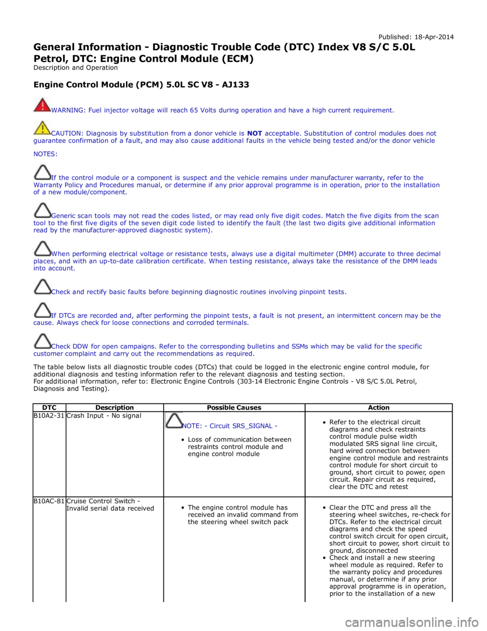
DTC Description Possible Causes Action B10A2-31 Crash Input - No signal
NOTE: - Circuit SRS_SIGNAL -
Loss of communication between
restraints control module and
engine control module
Refer to the electrical circuit
diagrams and check restraints
control module pulse width
modulated SRS signal line circuit,
hard wired connection between
engine control module and restraints
control module for short circuit to
ground, short circuit to power, open
circuit. Repair circuit as required,
clear the DTC and retest B10AC-81
Cruise Control Switch -
Invalid serial data received
The engine control module has
received an invalid command from
the steering wheel switch pack
Clear the DTC and press all the
steering wheel switches, re-check for
DTCs. Refer to the electrical circuit
diagrams and check the speed
control switch circuit for open circuit,
short circuit to power, short circuit to
ground, disconnected
Check and install a new steering
wheel module as required. Refer to
the warranty policy and procedures
manual, or determine if any prior
approval programme is in operation,
prior to the installation of a new
Page 165 of 3039

DTC Description Possible Causes Action module/component B10AC-82 Cruise Control Switch - Alive / sequence counter incorrect / not updated
Cruise buttons alive counter is not
incrementing. Which suggests that
the LIN bus is faulty
Steering wheel module is not
connected
Steering wheel module failure
Refer to the electrical circuit
diagrams and check the speed
control switch circuit for open circuit,
short circuit to power, short circuit to
ground, disconnected
Refer to the electrical circuit
diagrams and check the LIN bus
between steering wheel module and
the CAN gateway
Check and install a new steering
wheel module as required. Refer to
the warranty policy and procedures
manual, or determine if any prior
approval programme is in operation,
prior to the installation of a new
module/component B10AC-83
Cruise Control Switch - Value
of signal protection
calculation incorrect
Cruise buttons checksum incorrect,
incorrect cruise switches fitted to
vehicle
Check and install new cruise
switches as required. Refer to the
warranty policy and procedures
manual, or determine if any prior
approval programme is in operation,
prior to the installation of a new
module/component B10AC-96
Cruise Control Switch -
Component internal failure
Speed control switch circuit, open
circuit, short circuit to power, short
circuit to ground, disconnected
Speed control switch failure
Steering wheel module failure
Check for related DTCs in other
central junction boxes
Refer to the electrical circuit
diagrams and check the speed
control switch circuit for open circuit,
short circuit to power, short circuit to
ground, disconnected
Check and install a new speed
control switch as required. Check and
install a new steering wheel module
as required. Refer to the warranty
policy and procedures manual, or
determine if any prior approval
programme is in operation, prior to
the installation of a new
module/component B10FF-68
Ignition Control - Event
information
Spark plug(s) fault
Wiring harness fault
Ignition coil(s) fault
Refer to repair manual and check
spark plug(s) for condition and
security. Replace any defective
components as required
Refer to electrical wiring diagrams
and check ignition coil circuit for
intermittent open circuit, short
circuit to power, short circuit to
ground
Check and install a new coil(s) as
required. Refer to the warranty policy
and procedures manual, or determine
if any prior approval programme is in
operation, prior to the installation of
a new module/component B11DB-01
Battery Monitoring Module -
General electrical failure
NOTE: - Circuit BATTERY -
Charging system fault Battery
monitoring signal line
circuit fault
Vehicle battery fault
Refer to electrical wiring diagrams
and check charging system for faults.
Perform any repairs required
Refer to the electrical wiring
diagrams and check the battery
monitoring system module circuit for
open circuit, short circuit to ground,
short circuit to power
Refer to the workshop manual and
the battery care manual, inspect the
vehicle battery and ensure it is fully
charged and serviceable before
performing further tests
Page 195 of 3039

DTC Description Possible Causes Action B1D37-11
Wiper Switch
Connection Circuit -
Circuit short to ground
Flick wipe switch circuit -
short to ground
Refer to the electrical circuit diagrams and check
flick wipe switch circuit for short to ground B1D37-15
Wiper Switch
Connection Circuit -
Circuit short to battery
or open
Flick wipe switch circuit -
short to power, open circuit
Carry out any pinpoint tests associated with this
DTC using the manufacturer approved diagnostic
system. Refer to the electrical circuit diagrams
and check flick wipe switch circuit for short to
power, open circuit C1110-64
Power steering
Calibration Data - Signal
plausibility failure
Invalid VAPS curve loaded
Re-configure the instrument cluster as new to
download VAPS curve data P0635-11
Power Steering Control
Circuit - Circuit short to
ground
VAPS ignition supply circuit
- short to ground
Refer to the electrical circuit diagrams and check
VAPS ignition supply circuit for short to ground P0635-12
Power Steering Control
Circuit - Circuit short to
battery
VAPS ignition supply circuit
- short to power
Refer to the electrical circuit diagrams and check
VAPS ignition supply circuit for short to power P0635-13
Power Steering Control
Circuit - Circuit open
VAPS ignition supply circuit
- open circuit
Refer to the electrical circuit diagrams and check
VAPS ignition supply circuit for open circuit P0635-22
Power Steering Control
Circuit - Signal
amplitude > maximum
First valid received speed
value above threshold
Check ABS module for DTCs and refer to relevant
DTC Index P0635-44
Power Steering Control
Circuit - Data memory
failure
Data memory failure
Re-configure the instrument cluster as new to
download VAPS curve data U0001-88
High Speed CAN
Communication Bus -
Bus off
Bus Off
Carry out any pinpoint tests associated with this
DTC using the manufacturer approved diagnostic
system. Carry out CAN network integrity test
using the manufacturer approved diagnostic
system. Refer to the electrical circuit diagrams
and check HS CAN network to instrument cluster U0010-88
Medium Speed CAN
Communication Bus -
Bus off
Bus Off
Carry out any pinpoint tests associated with this
DTC using the manufacturer approved diagnostic
system. Carry out CAN network integrity test
using the manufacturer approved diagnostic
system. Refer to the electrical circuit diagrams
and check MS CAN network to instrument cluster U0100-00
Lost Communication
With ECM/PCM “A” - No
sub type information
Loss of CAN communication
with ECM
Carry out any pinpoint tests associated with this
DTC using the manufacturer approved diagnostic
system. Check ECM for DTCs and refer to the
relevant DTC Index U0101-00
Lost Communication
with TCM - No sub type
information
Loss of CAN communication
with TCM
Carry out any pinpoint tests associated with this
DTC using the manufacturer approved diagnostic
system. Check TCM for DTCs and refer to the
relevant DTC Index U0103-00
Lost Communication
With Gear Shift Module
- No sub type
information
Loss of CAN communication
with transmission shift
module
Carry out any pinpoint tests associated with this
DTC using the manufacturer approved diagnostic
system. Check transmission shift module for
DTCs and refer to the relevant DTC Index U0104-00
Lost Communication
With Cruise Control
Module - No sub type
information
Loss of CAN communication
with speed control module
Carry out any pinpoint tests associated with this
DTC using the manufacturer approved diagnostic
system. Check speed control module for DTCs
and refer to the relevant DTC Index U0121-00
Lost Communication
With Anti-Lock Brake
System (ABS) Control
Module - No sub type
information
Loss of CAN communication
with ABS module
Carry out any pinpoint tests associated with this
DTC using the manufacturer approved diagnostic
system. Check ABS module for DTCs and refer to
the relevant DTC Index
Page 692 of 3039
Published: 11-May-2011
Anti-Lock Control - Stability Assist - Anti-Lock Control - Stability Assist - Overview
Description and Operation
Overview
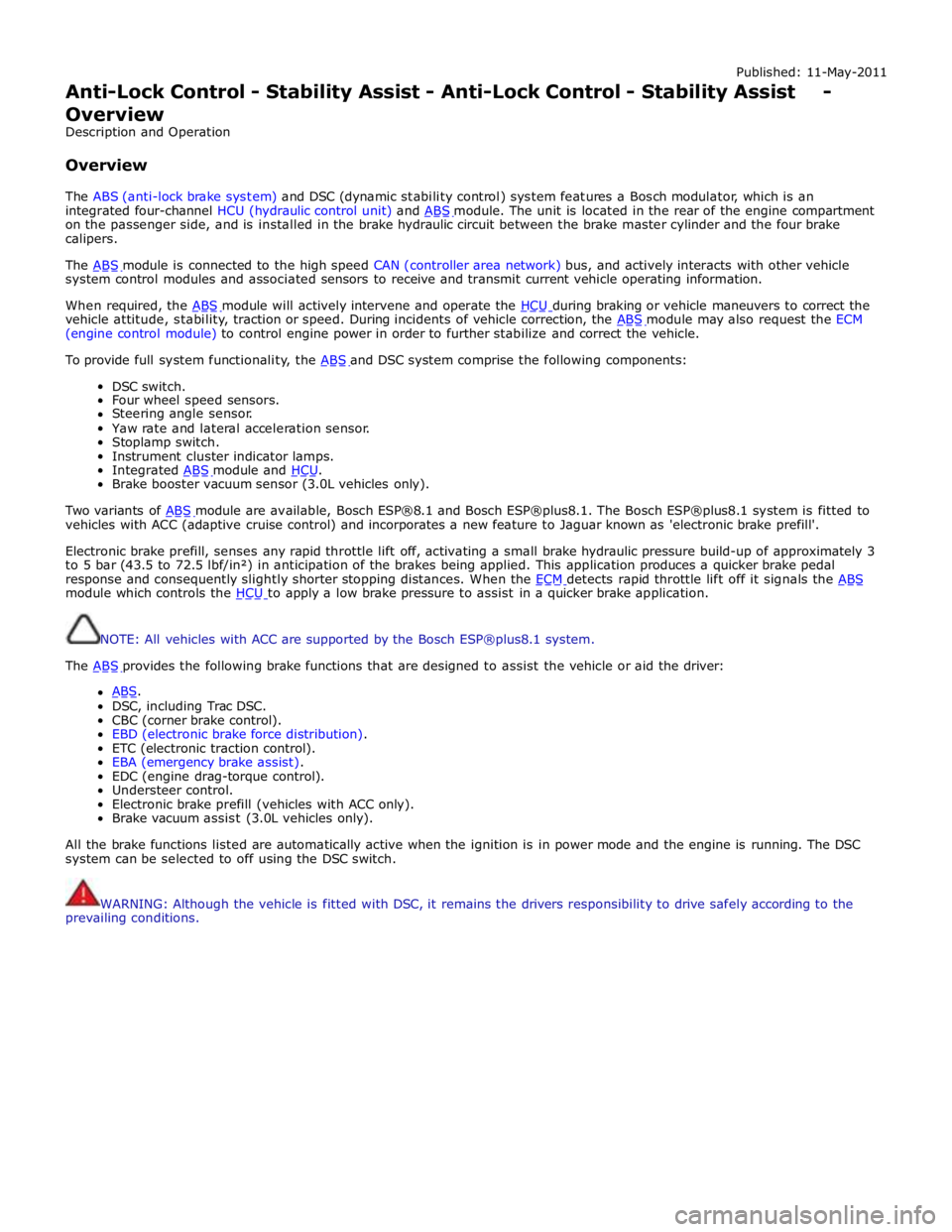
The ABS (anti-lock brake system) and DSC (dynamic stability control) system features a Bosch modulator, which is an
integrated four-channel HCU (hydraulic control unit) and ABS module. The unit is located in the rear of the engine compartment on the passenger side, and is installed in the brake hydraulic circuit between the brake master cylinder and the four brake
calipers.
The ABS module is connected to the high speed CAN (controller area network) bus, and actively interacts with other vehicle system control modules and associated sensors to receive and transmit current vehicle operating information.
When required, the ABS module will actively intervene and operate the HCU during braking or vehicle maneuvers to correct the vehicle attitude, stability, traction or speed. During incidents of vehicle correction, the ABS module may also request the ECM (engine control module) to control engine power in order to further stabilize and correct the vehicle.
To provide full system functionality, the ABS and DSC system comprise the following components: DSC switch.
Four wheel speed sensors.
Steering angle sensor.
Yaw rate and lateral acceleration sensor.
Stoplamp switch.
Instrument cluster indicator lamps.
Integrated ABS module and HCU. Brake booster vacuum sensor (3.0L vehicles only).
Two variants of ABS module are available, Bosch ESP®8.1 and Bosch ESP®plus8.1. The Bosch ESP®plus8.1 system is fitted to vehicles with ACC (adaptive cruise control) and incorporates a new feature to Jaguar known as 'electronic brake prefill'.
Electronic brake prefill, senses any rapid throttle lift off, activating a small brake hydraulic pressure build-up of approximately 3
to 5 bar (43.5 to 72.5 lbf/in²) in anticipation of the brakes being applied. This application produces a quicker brake pedal
response and consequently slightly shorter stopping distances. When the ECM detects rapid throttle lift off it signals the ABS module which controls the HCU to apply a low brake pressure to assist in a quicker brake application.
NOTE: All vehicles with ACC are supported by the Bosch ESP®plus8.1 system.
The ABS provides the following brake functions that are designed to assist the vehicle or aid the driver: ABS. DSC, including Trac DSC.
CBC (corner brake control).
EBD (electronic brake force distribution).
ETC (electronic traction control).
EBA (emergency brake assist).
EDC (engine drag-torque control).
Understeer control.
Electronic brake prefill (vehicles with ACC only).
Brake vacuum assist (3.0L vehicles only).
All the brake functions listed are automatically active when the ignition is in power mode and the engine is running. The DSC
system can be selected to off using the DSC switch.
WARNING: Although the vehicle is fitted with DSC, it remains the drivers responsibility to drive safely according to the
prevailing conditions.
Page 695 of 3039
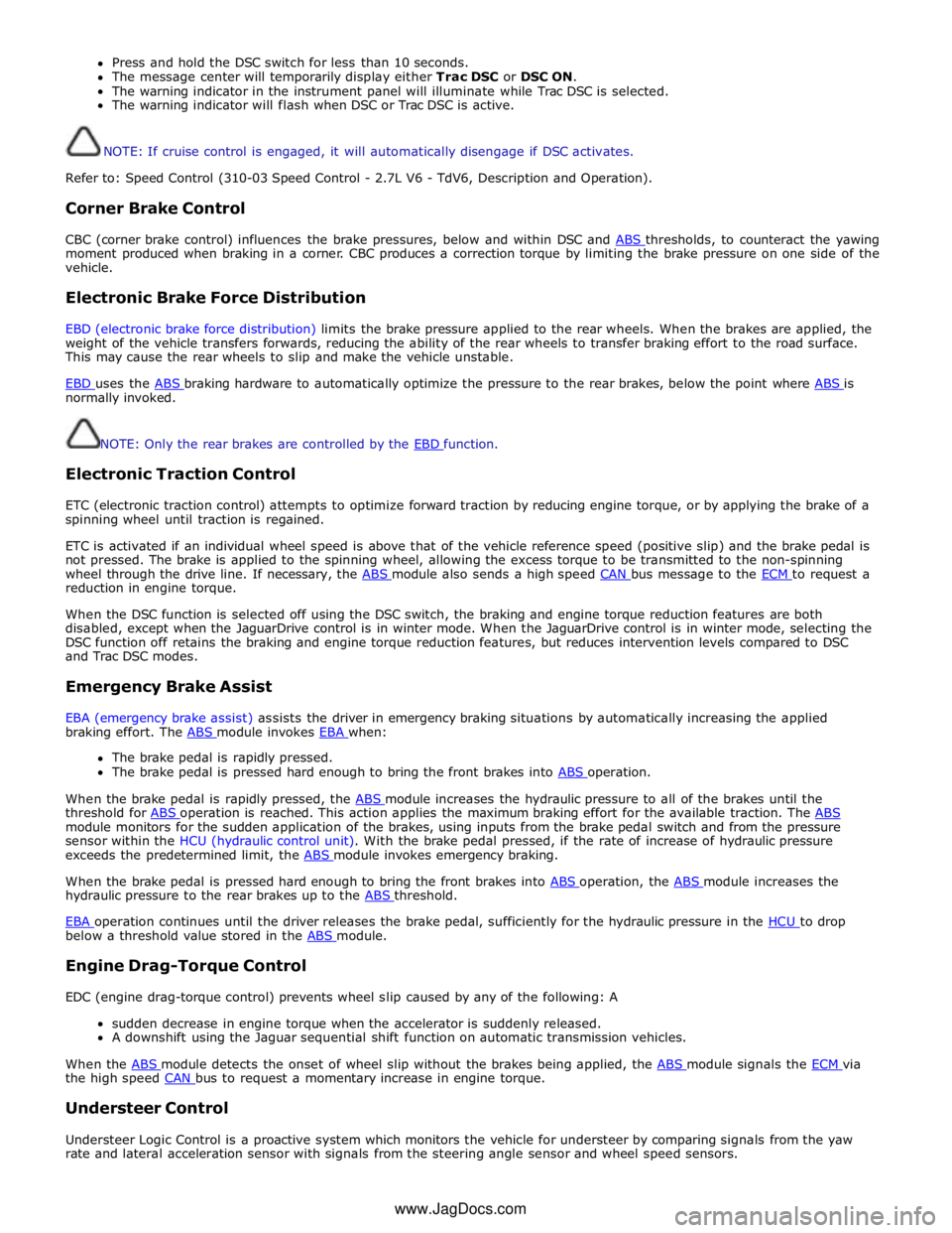
Press and hold the DSC switch for less than 10 seconds.
The message center will temporarily display either Trac DSC or DSC ON.
The warning indicator in the instrument panel will illuminate while Trac DSC is selected.
The warning indicator will flash when DSC or Trac DSC is active.
NOTE: If cruise control is engaged, it will automatically disengage if DSC activates.
Refer to: Speed Control (310-03 Speed Control - 2.7L V6 - TdV6, Description and Operation).
Corner Brake Control
CBC (corner brake control) influences the brake pressures, below and within DSC and ABS thresholds, to counteract the yawing moment produced when braking in a corner. CBC produces a correction torque by limiting the brake pressure on one side of the
vehicle.
Electronic Brake Force Distribution
EBD (electronic brake force distribution) limits the brake pressure applied to the rear wheels. When the brakes are applied, the
weight of the vehicle transfers forwards, reducing the ability of the rear wheels to transfer braking effort to the road surface.
This may cause the rear wheels to slip and make the vehicle unstable.
EBD uses the ABS braking hardware to automatically optimize the pressure to the rear brakes, below the point where ABS is normally invoked.
NOTE: Only the rear brakes are controlled by the EBD function.
Electronic Traction Control
ETC (electronic traction control) attempts to optimize forward traction by reducing engine torque, or by applying the brake of a
spinning wheel until traction is regained.
ETC is activated if an individual wheel speed is above that of the vehicle reference speed (positive slip) and the brake pedal is
not pressed. The brake is applied to the spinning wheel, allowing the excess torque to be transmitted to the non-spinning
wheel through the drive line. If necessary, the ABS module also sends a high speed CAN bus message to the ECM to request a reduction in engine torque.
When the DSC function is selected off using the DSC switch, the braking and engine torque reduction features are both
disabled, except when the JaguarDrive control is in winter mode. When the JaguarDrive control is in winter mode, selecting the
DSC function off retains the braking and engine torque reduction features, but reduces intervention levels compared to DSC
and Trac DSC modes.
Emergency Brake Assist
EBA (emergency brake assist) assists the driver in emergency braking situations by automatically increasing the applied
braking effort. The ABS module invokes EBA when: The brake pedal is rapidly pressed.
The brake pedal is pressed hard enough to bring the front brakes into ABS operation.
When the brake pedal is rapidly pressed, the ABS module increases the hydraulic pressure to all of the brakes until the threshold for ABS operation is reached. This action applies the maximum braking effort for the available traction. The ABS module monitors for the sudden application of the brakes, using inputs from the brake pedal switch and from the pressure
sensor within the HCU (hydraulic control unit). With the brake pedal pressed, if the rate of increase of hydraulic pressure
exceeds the predetermined limit, the ABS module invokes emergency braking.
When the brake pedal is pressed hard enough to bring the front brakes into ABS operation, the ABS module increases the hydraulic pressure to the rear brakes up to the ABS threshold.
EBA operation continues until the driver releases the brake pedal, sufficiently for the hydraulic pressure in the HCU to drop below a threshold value stored in the ABS module.
Engine Drag-Torque Control
EDC (engine drag-torque control) prevents wheel slip caused by any of the following: A
sudden decrease in engine torque when the accelerator is suddenly released.
A downshift using the Jaguar sequential shift function on automatic transmission vehicles.
When the ABS module detects the onset of wheel slip without the brakes being applied, the ABS module signals the ECM via the high speed CAN bus to request a momentary increase in engine torque.
Understeer Control
Understeer Logic Control is a proactive system which monitors the vehicle for understeer by comparing signals from the yaw
rate and lateral acceleration sensor with signals from the steering angle sensor and wheel speed sensors. www.JagDocs.com
Page 696 of 3039
a decrease in engine torque. At the same time the ABS module will control the HCU to apply brake pressure to the relevant wheels to correct the understeer.
Electronic Brake Prefill (Vehicles With ACC Only)
Electronic brake prefill (Bosch ESP®plus8.1), senses any rapid throttle lift off, activating a small brake hydraulic pressure
build-up of approximately 3 to 5 bar (43.5 to 72.5 lbf/in²) in anticipation of the brakes being applied.
This application produces a quicker brake pedal response and consequently slightly shorter stopping distances. The system
supports vehicles with ACC (adaptive cruise control).
When the ABS module detects rapid throttle lift off (from the signals received from the ECM over the high speed CAN bus), it controls the HCU to apply a low brake pressure to assist in a quicker brake application.
Brake Vacuum Assist (3.0L Vehicles Only)
Operation of Brake Vacuum Assist generally occurs at the beginning of an ignition cycle when brake booster vacuum levels are
low; refer to Brake Booster Vacuum sensor, below.
Brake vacuum assist operation will be recognized by the driver experiencing a vibrating brake pedal and slight modulator noise.
This will be similar to that experienced when ABS system is operating.
As the engine warms up, Brake Vacuum Assist operation will become less frequent. However, it can be become more active
when vacuum levels are low due to driving at high-altitudes, or during frequent heavy-braking.
Noise levels during Brake Vacuum Assist may vary with initial system activity being the loudest observed. In some
circumstances initial activity may be interpreted as a 'thump' noise, particularly if there is no immediate and significant Brake
Vacuum Assist functionality.
In this circumstance system behavior is normal and should not be a cause for fault investigation.
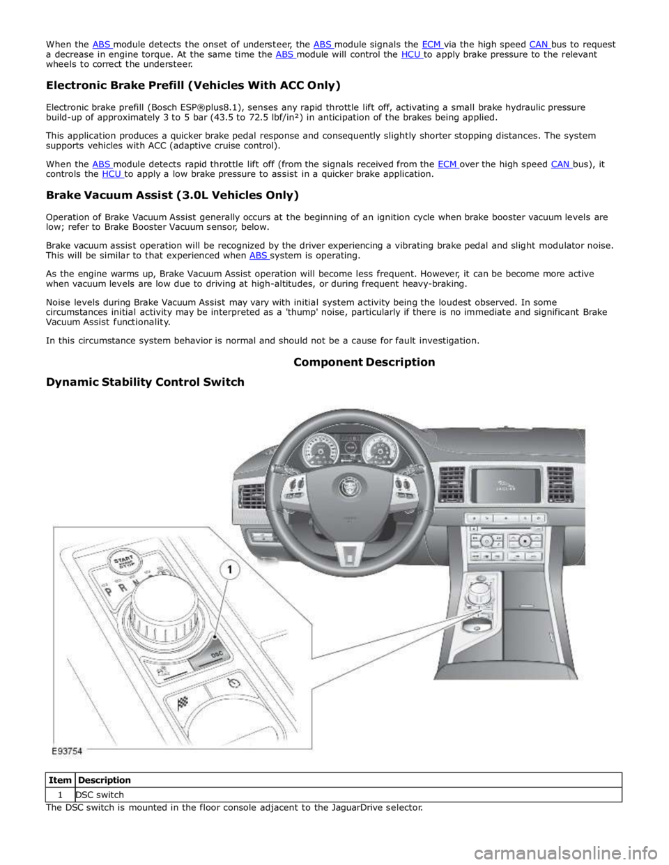
Dynamic Stability Control Switch Component Description
Item Description 1 DSC switch The DSC switch is mounted in the floor console adjacent to the JaguarDrive selector.
Page 876 of 3039
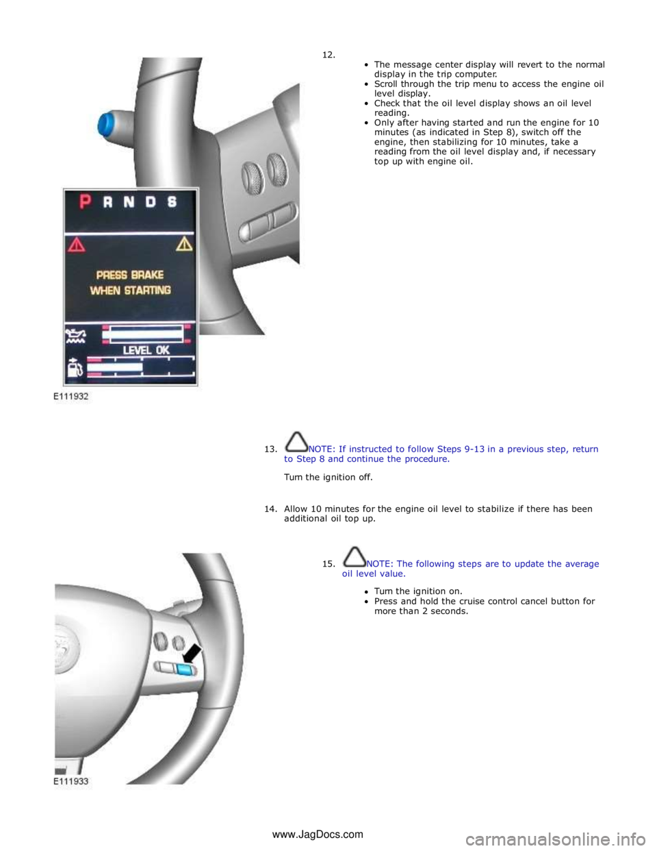
12.
The message center display will revert to the normal
display in the trip computer.
Scroll through the trip menu to access the engine oil
level display.
Check that the oil level display shows an oil level
reading.
Only after having started and run the engine for 10
minutes (as indicated in Step 8), switch off the
engine, then stabilizing for 10 minutes, take a
reading from the oil level display and, if necessary
top up with engine oil.
13. NOTE: If instructed to follow Steps 9-13 in a previous step, return
to Step 8 and continue the procedure.
Turn the ignition off.
14. Allow 10 minutes for the engine oil level to stabilize if there has been
additional oil top up.
15. NOTE: The following steps are to update the average
oil level value.
Turn the ignition on.
Press and hold the cruise control cancel button for
more than 2 seconds. www.JagDocs.com
Page 883 of 3039
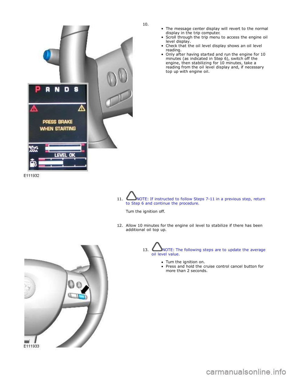
10.
The message center display will revert to the normal
display in the trip computer.
Scroll through the trip menu to access the engine oil
level display.
Check that the oil level display shows an oil level
reading.
Only after having started and run the engine for 10
minutes (as indicated in Step 6), switch off the
engine, then stabilizing for 10 minutes, take a
reading from the oil level display and, if necessary
top up with engine oil.
11. NOTE: If instructed to follow Steps 7-11 in a previous step, return
to Step 6 and continue the procedure.
Turn the ignition off.
12. Allow 10 minutes for the engine oil level to stabilize if there has been
additional oil top up.
13. NOTE: The following steps are to update the average
oil level value.
Turn the ignition on.
Press and hold the cruise control cancel button for
more than 2 seconds.