instrument cluster JAGUAR XFR 2010 1.G Workshop Manual
[x] Cancel search | Manufacturer: JAGUAR, Model Year: 2010, Model line: XFR, Model: JAGUAR XFR 2010 1.GPages: 3039, PDF Size: 58.49 MB
Page 2035 of 3039
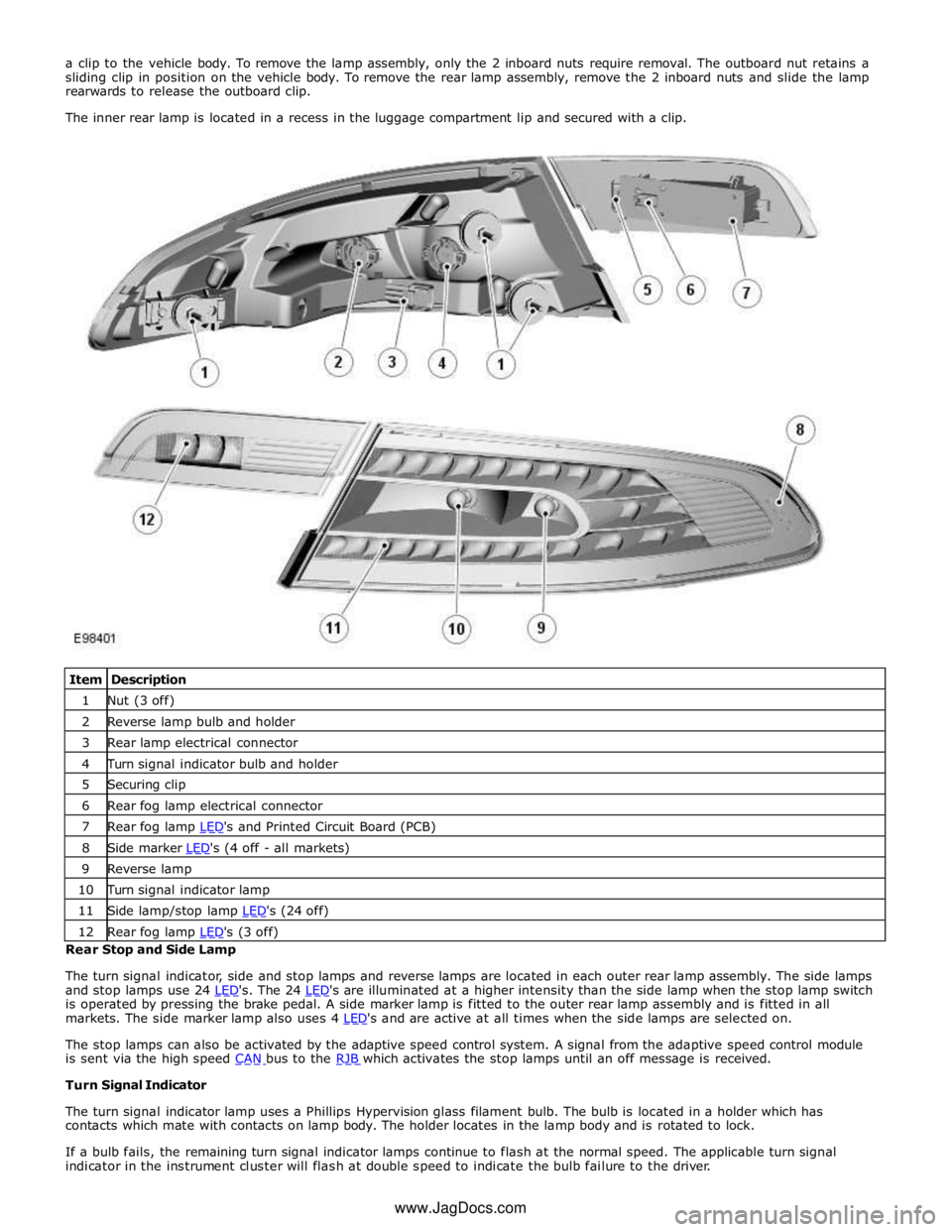
1 Nut (3 off) 2 Reverse lamp bulb and holder 3 Rear lamp electrical connector 4 Turn signal indicator bulb and holder 5 Securing clip 6 Rear fog lamp electrical connector 7 Rear fog lamp LED's and Printed Circuit Board (PCB) 8 Side marker LED's (4 off - all markets) 9 Reverse lamp 10 Turn signal indicator lamp 11 Side lamp/stop lamp LED's (24 off) 12 Rear fog lamp LED's (3 off) Rear Stop and Side Lamp
The turn signal indicator, side and stop lamps and reverse lamps are located in each outer rear lamp assembly. The side lamps
and stop lamps use 24 LED's. The 24 LED's are illuminated at a higher intensity than the side lamp when the stop lamp switch is operated by pressing the brake pedal. A side marker lamp is fitted to the outer rear lamp assembly and is fitted in all
markets. The side marker lamp also uses 4 LED's and are active at all times when the side lamps are selected on.
The stop lamps can also be activated by the adaptive speed control system. A signal from the adaptive speed control module
is sent via the high speed CAN bus to the RJB which activates the stop lamps until an off message is received. Turn Signal Indicator
The turn signal indicator lamp uses a Phillips Hypervision glass filament bulb. The bulb is located in a holder which has
contacts which mate with contacts on lamp body. The holder locates in the lamp body and is rotated to lock.
If a bulb fails, the remaining turn signal indicator lamps continue to flash at the normal speed. The applicable turn signal
indicator in the instrument cluster will flash at double speed to indicate the bulb failure to the driver. www.JagDocs.com
Page 2038 of 3039
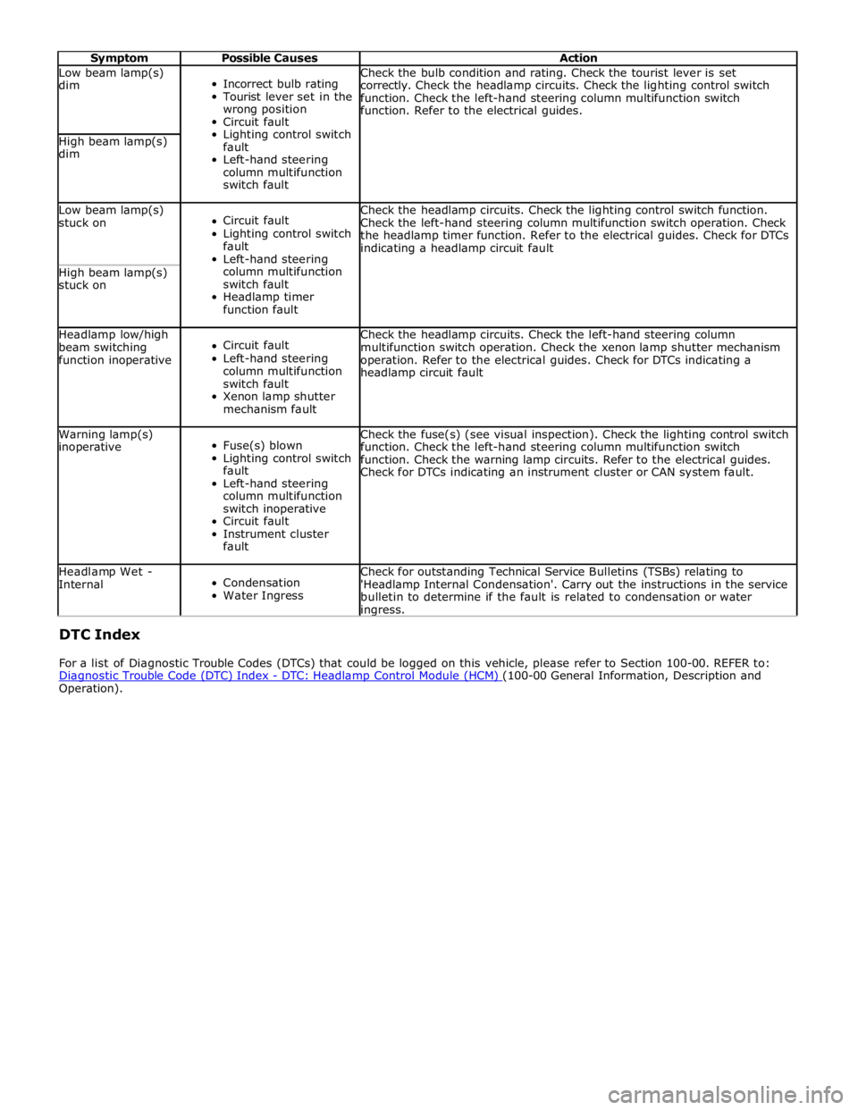
Symptom Possible Causes Action Low beam lamp(s)
dim
Incorrect bulb rating
Tourist lever set in the
wrong position
Circuit fault
Lighting control switch
fault
Left-hand steering
column multifunction
switch fault Check the bulb condition and rating. Check the tourist lever is set
correctly. Check the headlamp circuits. Check the lighting control switch
function. Check the left-hand steering column multifunction switch
function. Refer to the electrical guides. High beam lamp(s)
dim Low beam lamp(s)
stuck on
Circuit fault
Lighting control switch
fault
Left-hand steering
column multifunction
switch fault
Headlamp timer
function fault Check the headlamp circuits. Check the lighting control switch function.
Check the left-hand steering column multifunction switch operation. Check
the headlamp timer function. Refer to the electrical guides. Check for DTCs
indicating a headlamp circuit fault High beam lamp(s)
stuck on Headlamp low/high
beam switching
function inoperative
Circuit fault
Left-hand steering
column multifunction
switch fault
Xenon lamp shutter
mechanism fault Check the headlamp circuits. Check the left-hand steering column
multifunction switch operation. Check the xenon lamp shutter mechanism
operation. Refer to the electrical guides. Check for DTCs indicating a
headlamp circuit fault Warning lamp(s)
inoperative
Fuse(s) blown
Lighting control switch
fault
Left-hand steering
column multifunction
switch inoperative
Circuit fault
Instrument cluster
fault Check the fuse(s) (see visual inspection). Check the lighting control switch
function. Check the left-hand steering column multifunction switch
function. Check the warning lamp circuits. Refer to the electrical guides.
Check for DTCs indicating an instrument cluster or CAN system fault. Headlamp Wet -
Internal
Condensation
Water Ingress Check for outstanding Technical Service Bulletins (TSBs) relating to
'Headlamp Internal Condensation'. Carry out the instructions in the service
bulletin to determine if the fault is related to condensation or water ingress. DTC Index
For a list of Diagnostic Trouble Codes (DTCs) that could be logged on this vehicle, please refer to Section 100-00. REFER to:
Diagnostic Trouble Code (DTC) Index - DTC: Headlamp Control Module (HCM) (100-00 General Information, Description and Operation).
Page 2066 of 3039
Published: 11-May-2011
Daytime Running Lamps (DRL) - Daytime Running Lamps (DRL) - System
Operation and Component Description
Description and Operation
CENTRAL JUNCTION BOX (CJB) System Operation
The CJB (central junction box) controls the operation of the DRL (daytime running lamps). The DRL are activated once the CJB detects an ignition on power mode 6 signal.
The CJB also monitors the lighting control switch and the auto lamps feature and overrides the DRL if required.
DAYTIME RUNNING LAMPS - CANADA Component Description
The DRL for this market use full intensity low beam headlamps. The side marker lamps, tail lamps and license plate lamps will be on, but instrument cluster illumination will be off. DRL are active when the following parameters are met:
PARK is not selected on the electronic transmission selector
Electronic Parking Brake (EPB) is off
Power mode 6 (ignition on) detected by the CJB The CJB receives an engine running signal The lighting control switch is in the off or side lamps position.
NOTES:
If the lighting control switch is moved to the headlamp position, DRL are deactivated and normal side lamp and headlamp functionality is operational.
When DRL are active, the headlamp flash function using the left hand steering column multifunction switch will operate normally.
The high beam headlamp function using the left hand steering column stalk switch will be deactivated. When the transmission
is in PARK, DRL are turned off. This is to reduce battery discharge during long periods of engine idling in cold climate conditions. When the electronic transmission selector is moved from the PARK position, normal DRL functionality is restored.
DAYTIME RUNNING LAMPS - DENMARK, HOLLAND, NORWAY, SWEDEN, FINLAND AND POLAND
NOTE: DRL for Poland is on vehicles from 2008MY.
DRL for these markets use full intensity low beam headlamps. Side lamps and license plate lamps will be on, but instrument cluster illumination will be off. DRL are active when the following parameters are met:
Power mode 6 (ignition on) detected by the CJB The CJB receives an engine running signal The lighting control switch is in the off position.
NOTE: When DRL are active, the headlamp flash function using the left hand steering column multifunction switch will operate normally. The high beam headlamp function using the left hand steering column stalk switch will be deactivated.
If the lighting control switch is moved to the side lamp or headlamp positions, DRL are deactivated and normal side lamp and headlamp functionality is operational.
AUTOMATIC HEADLAMPS
On vehicles fitted with the automatic headlamps feature, DRL are overridden if the lighting control switch is in the 'Auto' position and the CJB receives a signal from the rain/light sensor to activate the exterior lights.
When the CJB receives a signal to de-activate the automatic headlamps feature the DRL function is restored providing the parameters for DRL activation are met.
Page 2069 of 3039

5 RJB (rear junction box) 6 Battery monitoring system module 7 Rear view camera 8 TCM (transmission control module) 9 Generator 10 Driver's door switch pack 11 Rear door control module 12 Driver's door control module 13 ECM (engine control module) 14 Electronic transmission selector 15 Driver's seat module 16 Driver's seat switch pack 17 Rear door control module 18 Front passenger door control module 19 Clockspring 20 Audio and telephone steering wheel switches 21 Instrument cluster 22 Start control module
Page 2071 of 3039

N = Medium speed CAN (controller area network) bus 1 Parking aid module 2 RJB 3 Keyless vehicle module 4 RH blind spot monitoring module 5 Driver's seat module 6 Front seat climate control module 7 Information control module 8 ATC module 9 CJB 10 Diagnostic socket 11 Instrument cluster 12 Integrated control panel 13 Front passenger door control module
Page 2072 of 3039
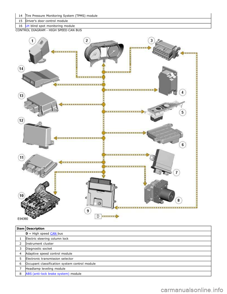
Tire Pressure Monitoring System (TPMS) module 15 Driver's door control module 16 LH blind spot monitoring module CONTROL DIAGRAM - HIGH SPEED CAN BUS
Item Description D = High speed CAN bus 1 Electric steering column lock 2 Instrument cluster 3 Diagnostic socket 4 Adaptive speed control module 5 Electronic transmission selector 6 Occupant classification system control module 7 Headlamp leveling module 8 ABS (anti-lock brake system) module
Page 2085 of 3039

DTC Description Possible Cause Action B100951
Ignition
Authorisation
Faulty instrument cluster
Target SID re-synchronisation
error following programming
CAN fault Check ignition, power and ground supplies to CJB and
instrument cluster. Re-synchronize ID by re-configuring
the instrument cluster as a new module. Check CAN
communications between instrument cluster and tester B100962
Ignition
Authorisation
Low speed CAN fault
CJB fault
Instrument cluster fault
Incorrect module installed
(CJB/Instrument cluster)
Target SID synchronisation
error following re-programming
Noise/EMC related error Check CAN communications between CJB and instrument
cluster. Check ignition, power and ground supplies to CJB
and instrument cluster. Confirm correct module is
installed. Re-synchronise ID by re-configuring the
instrument cluster as a new module. Check CAN network
for interference/EMC related issues B100963
Ignition
Authorisation
CJB fault
Low speed CAN fault
Instrument cluster fault
Low battery voltage <9V Check Power and Ground supplies to CJB and instrument
cluster. Check CAN communications between CJB and
instrument cluster. Check battery is in fully charged and
serviceable condition, refer to the battery care manual B100964
Ignition
Authorisation
CJB fault
Low speed CAN fault
Instrument cluster fault Check power and ground supplies to CJB and instrument
cluster. Check CAN communications between CJB and
instrument cluster B102B67 Passive Key
CJB fault
Low speed CAN fault
Remote Keyless Entry (RKE)
module fault
Write target SID
synchronisation error following
re-programming Check power and ground supplies to CJB and RKE
module. Check CAN communications between CJB and
RKE module. Re-synchronise ID by re-configuring the RKE
module as a new module B102B87 Passive Key
CJB fault
Low speed CAN fault
RKE module fault
Key fob battery low/battery
contact issue
Interference from other RF
signal
EMC/noise
Receiver fault
Receiver not programmed
correctly
Serial communications fault
(between receiver and RKE
module)
Key fault
Passive antenna fault
Confirm placement of key
within vehicle Check power and ground supplies to CJB, RKE module
and receiver. Check CAN communications between CJB
and instrument cluster. Check key fob battery. Confirm
vehicle surroundings, move vehicle. Check CAN network
for interference/EMC related issues. Disconnect battery,
then re-connect - confirm operation by re-programming
keys. Check serial circuit between receiver and RKE
module. Confirm spare key works. Refer to the electrical
circuit diagrams and test circuits to all 3 antennas. Check
whereabouts of key B108413
Boot/Trunk Motor
Close Switch
Trunk latch open signal circuit -
open circuit Refer to the electrical circuit diagrams and check trunk
latch open signal circuit for open circuit B108783 LIN Bus "A"
Checksum of the received LIN
frame from battery backed
sounder, roof header console,
and/or rain/light sensor is
incorrect Check operation of rain/light sensor by covering sensor or
applying water to screen, install a new sensor as
required B108788 LIN Bus "A"
Bus off. Battery backed
sounder, roof header console,
and/or rain/light sensor LIN
circuit - short to ground, power Carry out any pinpoint tests associated with this DTC
using the manufacturer approved diagnostic system.
Refer to the electrical circuit diagrams and check battery
backed sounder, roof header console, and rain/light
sensor LIN circuit for short to ground, power B108A11 Start Button
Start/Stop switch analogue
input circuits 1 or 2 - short to
ground Refer to the electrical circuit diagrams and check
Start/Stop switch analogue input circuits 1 and 2 for
short to ground www.JagDocs.com
Page 2091 of 3039

DTC Description Possible Cause Action B1D2711
Heater Coolant
Pump
Heater coolant pump control
circuit - short to ground Carry out any pinpoint tests associated with this DTC
using the manufacturer approved diagnostic system.
Refer to the electrical circuit diagrams and check heater
coolant pump control circuit for short to ground B1D2713
Heater Coolant
Pump
Heater coolant pump control
circuit - open circuit Carry out any pinpoint tests associated with this DTC
using the manufacturer approved diagnostic system.
Refer to the electrical circuit diagrams and check heater
coolant pump control circuit for open circuit B1D9796 Tilt Sensor
Component internal failure Suspect the battery backed sounder, check and install a
new battery backed sounder as required P057112
Brake Switch A
Circuit
Footbrake switch circuit - short
to power Refer to the electrical circuit diagrams and check
footbrake switch circuit for short to power P080111
Reverse Inhibit
Control Circuit
Electrochromic rear view mirror,
reverse inhibit circuit - short to
ground Carry out any pinpoint tests associated with this DTC
using the manufacturer approved diagnostic system.
Refer to the electrical circuit diagrams and check
electrochromic rear view mirror, reverse inhibit circuit for
short to ground P080112
Reverse Inhibit
Control Circuit
Electrochromic rear view mirror,
reverse inhibit circuit - short to
power Refer to the electrical circuit diagrams and check
electrochromic rear view mirror, reverse inhibit circuit for
short to power P080113
Reverse Inhibit
Control Circuit
Electrochromic rear view mirror,
reverse inhibit circuit - open
circuit Refer to the electrical circuit diagrams and check
electrochromic rear view mirror, reverse inhibit circuit for
open circuit P085013
Park/Neutral Switch
Input Circuit
Park/Neutral signal circuit -
open circuit Refer to the electrical circuit diagrams and check
Park/Neutral signal circuit for open circuit P162413 Anti-theft System
RJB anti-theft signal circuit -
open circuit Refer to the electrical circuit diagrams and check RJB
anti-theft signal circuit for open circuit P254F13
Engine Hood Switch
Circuit/Open
Hood ajar switch signal circuit -
open circuit Refer to the electrical circuit diagrams and check hood
ajar switch signal circuit for open circuit U001988
Low Speed CAN
Communication Bus
Bus OFF Carry out any pinpoint tests associated with this DTC
using the manufacturer approved diagnostic system. U014200
Lost
Communication
With Body Control
Module "B"
No sub type information Carry out any pinpoint tests associated with this DTC
using the manufacturer approved diagnostic system. U015500
Lost
Communication
With Instrument
Panel Cluster (IPC)
Control Module
No sub type information Carry out any pinpoint tests associated with this DTC
using the manufacturer approved diagnostic system. U015600
Lost
Communication
With Information
Center "A"
No sub type information Carry out any pinpoint tests associated with this DTC
using the manufacturer approved diagnostic system. U016400
Lost
Communication
With HVAC Control
Module
No sub type information Carry out any pinpoint tests associated with this DTC
using the manufacturer approved diagnostic system. U016800
Lost
Communication
With Vehicle
Security Control
Module
No sub type information Check power and ground supplies to vehicle security
module U019900
Lost
Communication
With "Door Control
Module A"
No sub type information Carry out any pinpoint tests associated with this DTC
using the manufacturer approved diagnostic system. U020000
Lost
Communication
With "Door Control
Module B"
No sub type information Carry out any pinpoint tests associated with this DTC
using the manufacturer approved diagnostic system.
Page 2092 of 3039
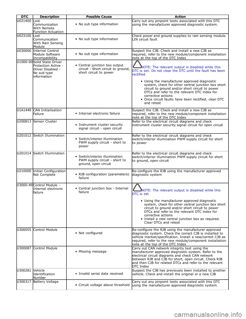
DTC Description Possible Cause Action U021400
Lost
Communication
With Remote
Function Actuation
No sub type information Carry out any pinpoint tests associated with this DTC
using the manufacturer approved diagnostic system. U023100
Lost
Communication
With Rain Sensing
Module
No sub type information Check power and ground supplies to rain sensing module.
LIN circuit fault U030000
Internal Control
Module Software Incompatibility
No sub type information Suspect the CJB. Check and install a new CJB as
required, refer to the new module/component installation
note at the top of the DTC Index U1000-00
Solid State Driver
Protection Active -
Driver Disabled -
No sub type
information
Central junction box output
circuit - Short circuit to ground,
short circuit to power
NOTE: The relevant output is disabled while this
DTC is set. Do not clear the DTC until the fault has been
rectified
Using the manufacturer approved diagnostic
system, check for other central junction box short
circuit to ground and/or short circuit to power
DTCs and refer to the relevant DTC index for
corrective actions
Once circuit faults have been rectified, clear DTC
and retest U1A1449
CAN Initialisation
Failure
Internal electronic failure Suspect the CJB. Check and install a new CJB as
required, refer to the new module/component installation
note at the top of the DTC Index U200813 Sensor Cluster
Instrument cluster security
signal circuit - open circuit Refer to the electrical circuit diagrams and check
instrument cluster security signal circuit for open circuit U201012 Switch Illumination
Switch/interior illumination
PWM supply circuit - short to
power Refer to the electrical circuit diagrams and check
switch/interior illumination PWM supply circuit for short
to power U201014 Switch Illumination
Switch/interior illumination
PWM supply circuit - short to
ground, open circuit Refer to the electrical circuit diagrams and check
switch/interior illumination PWM supply circuit for short
to ground, open circuit U210000
Initial Configuration
Not Complete
RJB configuration (parameters)
failure Re-configure the RJB using the manufacturer approved
diagnostic system U3000-49
Control Module -
Internal electronic
failure
Central junction box - Internal
failure
NOTE: The relevant output is disabled while this
DTC is set
Using the manufacturer approved diagnostic
system, check for other central junction box short
circuit to ground and/or short circuit to power
DTCs and refer to the relevant DTC index for
corrective actions
Install a new central junction box as required.
Clear DTCs and retest U300055 Control Module
Not configured Re-configure the RJB using the manufacturer approved
diagnostic system. Check the correct CJB is installed to
vehicle market/specification. Install a new/correct CJB as
required, refer to the new module/component installation
note at the top of the DTC Index U300087 Control Module
Missing message Carry out CAN network integrity test using the
manufacturer approved diagnostic system. Refer to the
electrical circuit diagrams and check CAN network
between RJB and CJB for short, open circuit. Check RJB
and then CJB for related DTCs and refer to the relevant
DTC Index U300281
Vehicle
Identification
Number
Invalid serial data received Suspect the CJB has previously been installed to another
vehicle. Check and install the original or a new CJB U300317 Battery Voltage
Circuit voltage above threshold Carry out any pinpoint tests associated with this DTC
using the manufacturer approved diagnostic system.
Page 2094 of 3039

DTC Description Possible Causes Action P123014
Fuel Pump Low
Speed
Malfunction
(VLCM)
High Side output not
driven - Diagnosis
feedback indicates output
is short to ground, open
circuit Refer to the electrical circuit diagrams and check fuel pump
delivery module for short to ground, open circuit P123093
Fuel Pump Low
Speed
Malfunction
(VLCM)
High Side output not
driven - Diagnosis
feedback indicates output
is at open load or short
to power Carry out any pinpoint test associated with this DTC using the
manufacturer approved diagnostic system. Refer to the electrical
circuit diagrams and check fuel pump delivery module for short to
power, open circuit P134611
Fuel Level Sensor
B Circuit
Fuel level sensor B
analogue input circuit -
short to ground Carry out any pinpoint test associated with this DTC using the
manufacturer approved diagnostic system. Refer to the electrical
circuit diagrams and check fuel level sensor B analogue input
circuit for short to ground P134615
Fuel Level Sensor
B Circuit
Fuel level sensor B
analogue input circuit -
short to power, open
circuit Carry out any pinpoint test associated with this DTC using the
manufacturer approved diagnostic system. Refer to the electrical
circuit diagrams and check fuel level sensor B analogue input
circuit for short to power, open circuit P162413 Anti-theft System
Anti-theft signal circuit
from CJB - open circuit Refer to the electrical circuit diagrams and check anti-theft signal
circuit from CJB for open circuit C111A11 Right Stop Lamp
Right stomp lamp control
circuit - short to ground Carry out any pinpoint test associated with this DTC using the
manufacturer approved diagnostic system. Refer to the electrical
circuit diagrams and check right stomp lamp control circuit for
short to ground C111A12 Right Stop Lamp
Right stomp lamp control
circuit - short to power Refer to the electrical circuit diagrams and check right stomp
lamp control circuit for short to power C111A13 Right Stop Lamp
Right stomp lamp control
circuit - open circuit Refer to the electrical circuit diagrams and check right stomp
lamp control circuit for open circuit C111B11 Left Stop Lamp
Left stomp lamp control
circuit - short to ground Carry out any pinpoint test associated with this DTC using the
manufacturer approved diagnostic system. Refer to the electrical
circuit diagrams and check left stomp lamp control circuit for
short to ground C111B13 Left Stop Lamp
Left stomp lamp control
circuit - open circuit Refer to the electrical circuit diagrams and check left stomp lamp
control circuit for open circuit C112011 Reversing lamp
Reverse lamp control
circuit - short to ground Carry out any pinpoint test associated with this DTC using the
manufacturer approved diagnostic system. Refer to the electrical
circuit diagrams and check reverse lamp control circuit for short
to ground C112012 Reversing lamp
Reverse lamp control
circuit - short to power Refer to the electrical circuit diagrams and check reverse lamp
control circuit for short to power C112013 Reversing lamp
Reverse lamp control
circuit - open circuit Refer to the electrical circuit diagrams and check reverse lamp
control circuit for open circuit C1120-15
Reversing lamp -
circuit short to
battery or open
Reverse lamp control
circuit - short circuit to
power, open circuit, high
resistance
Refer to the electrical circuit diagrams and check reverse
lamp control circuit for short circuit to power, open circuit,
high resistance. Repair wiring harness as required. Clear
DTC and retest B100A51
Fuel Pump
Authorisation
RJB fault
Low speed CAN fault
Instrument cluster fault Check power and ground supplies to RJB. Check CAN
communications between RJB and instrument cluster. Check
power and ground supplies to instrument cluster B100A62
Fuel Pump
Authorisation
Low speed CAN fault
RJB fault
Instrument cluster fault
Incorrect module
installed (RJB/Instrument
cluster) Check CAN communications between RJB and instrument cluster.
Check power and ground supplies to RJB and instrument cluster.
Confirm correct module installed. Re-synchronise ID by
re-configuring the RJB as a new module. Check CAN network for
interference/EMC related issues