sensor JAGUAR XFR 2010 1.G Workshop Manual
[x] Cancel search | Manufacturer: JAGUAR, Model Year: 2010, Model line: XFR, Model: JAGUAR XFR 2010 1.GPages: 3039, PDF Size: 58.49 MB
Page 703 of 3039
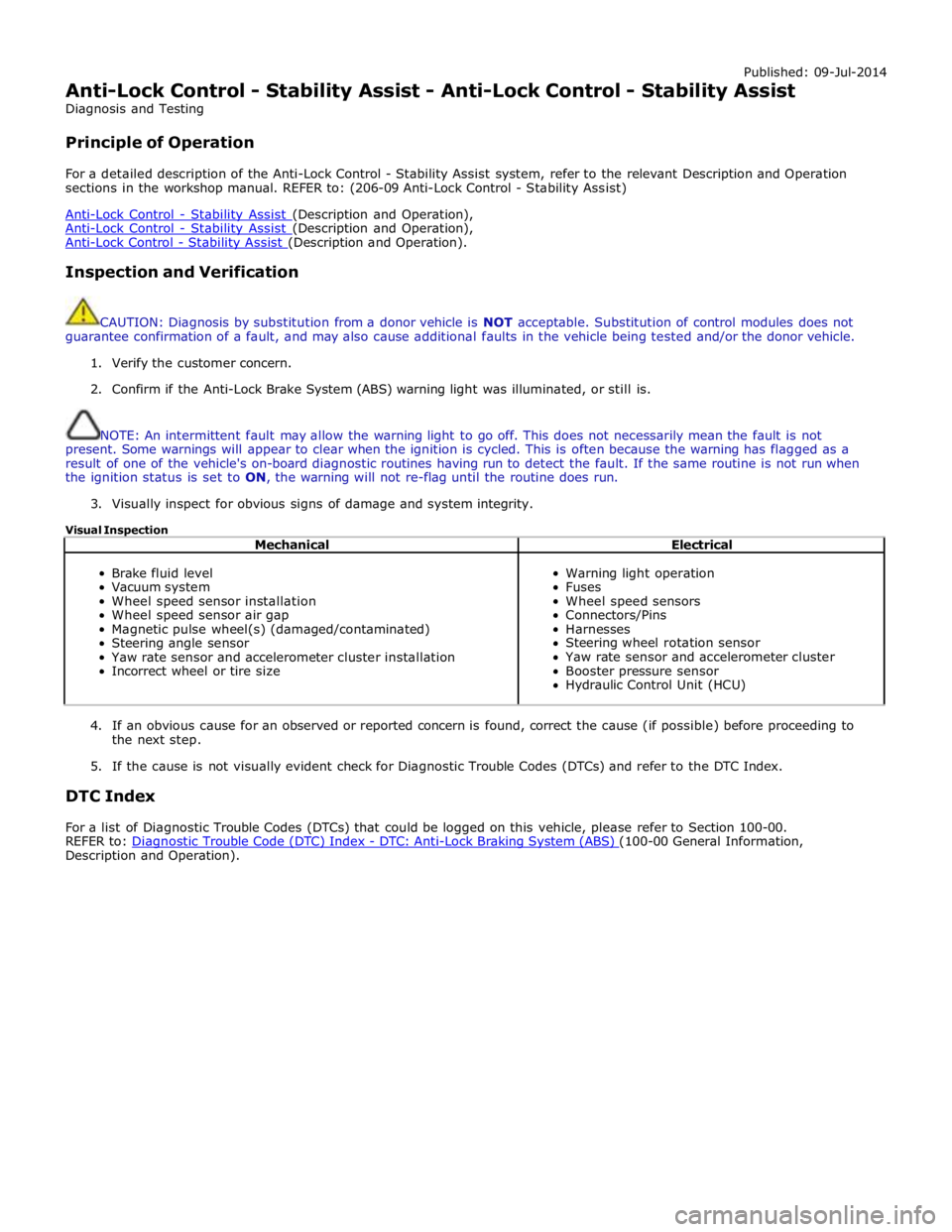
Published: 09-Jul-2014
Anti-Lock Control - Stability Assist - Anti-Lock Control - Stability Assist
Diagnosis and Testing
Principle of Operation
For a detailed description of the Anti-Lock Control - Stability Assist system, refer to the relevant Description and Operation
sections in the workshop manual. REFER to: (206-09 Anti-Lock Control - Stability Assist)
Anti-Lock Control - Stability Assist (Description and Operation), Anti-Lock Control - Stability Assist (Description and Operation), Anti-Lock Control - Stability Assist (Description and Operation).
Inspection and Verification
CAUTION: Diagnosis by substitution from a donor vehicle is NOT acceptable. Substitution of control modules does not
guarantee confirmation of a fault, and may also cause additional faults in the vehicle being tested and/or the donor vehicle.
1. Verify the customer concern.
2. Confirm if the Anti-Lock Brake System (ABS) warning light was illuminated, or still is.
NOTE: An intermittent fault may allow the warning light to go off. This does not necessarily mean the fault is not
present. Some warnings will appear to clear when the ignition is cycled. This is often because the warning has flagged as a
result of one of the vehicle's on-board diagnostic routines having run to detect the fault. If the same routine is not run when
the ignition status is set to ON, the warning will not re-flag until the routine does run.
3. Visually inspect for obvious signs of damage and system integrity.
Visual Inspection
Mechanical Electrical
Brake fluid level
Vacuum system
Wheel speed sensor installation
Wheel speed sensor air gap
Magnetic pulse wheel(s) (damaged/contaminated)
Steering angle sensor
Yaw rate sensor and accelerometer cluster installation
Incorrect wheel or tire size
Warning light operation
Fuses
Wheel speed sensors
Connectors/Pins
Harnesses
Steering wheel rotation sensor
Yaw rate sensor and accelerometer cluster
Booster pressure sensor
Hydraulic Control Unit (HCU)
4. If an obvious cause for an observed or reported concern is found, correct the cause (if possible) before proceeding to
the next step.
5. If the cause is not visually evident check for Diagnostic Trouble Codes (DTCs) and refer to the DTC Index.
DTC Index
For a list of Diagnostic Trouble Codes (DTCs) that could be logged on this vehicle, please refer to Section 100-00.
REFER to: Diagnostic Trouble Code (DTC) Index - DTC: Anti-Lock Braking System (ABS) (100-00 General Information, Description and Operation).
Page 705 of 3039
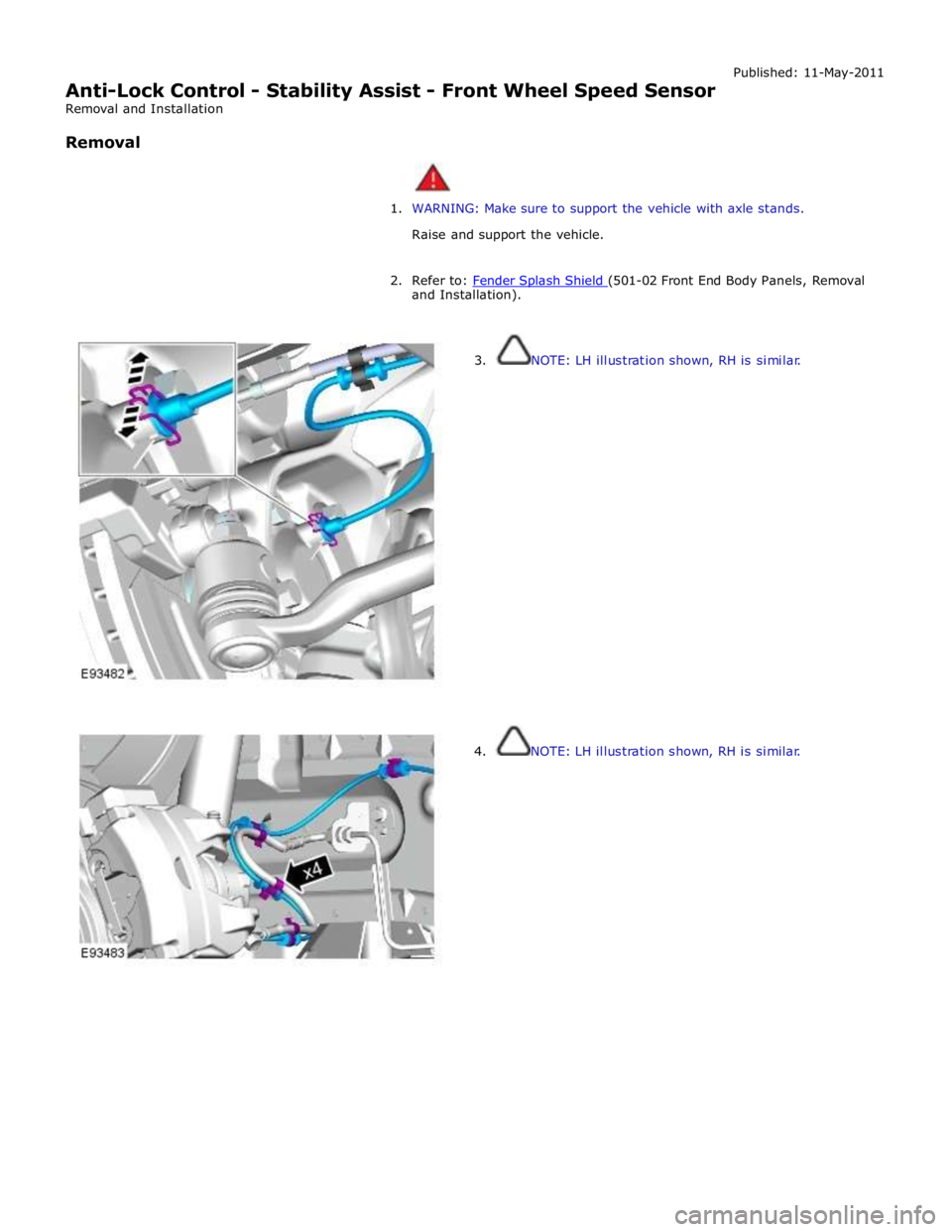
Anti-Lock Control - Stability Assist - Front Wheel Speed Sensor
Removal and Installation
Removal Published: 11-May-2011
1. WARNING: Make sure to support the vehicle with axle stands.
Raise and support the vehicle.
2. Refer to: Fender Splash Shield (501-02 Front End Body Panels, Removal and Installation).
3. NOTE: LH illustration shown, RH is similar.
4. NOTE: LH illustration shown, RH is similar.
Page 712 of 3039
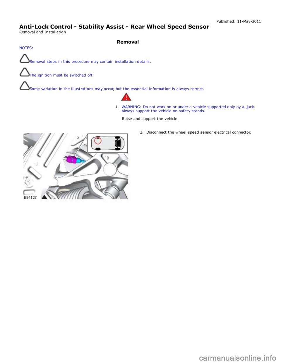
Anti-Lock Control - Stability Assist - Rear Wheel Speed Sensor
Removal and Installation Published: 11-May-2011
NOTES: Removal
Removal steps in this procedure may contain installation details.
The ignition must be switched off.
Some variation in the illustrations may occur, but the essential information is always correct.
1. WARNING: Do not work on or under a vehicle supported only by a jack.
Always support the vehicle on safety stands.
Raise and support the vehicle.
2. Disconnect the wheel speed sensor electrical connector.
Page 713 of 3039
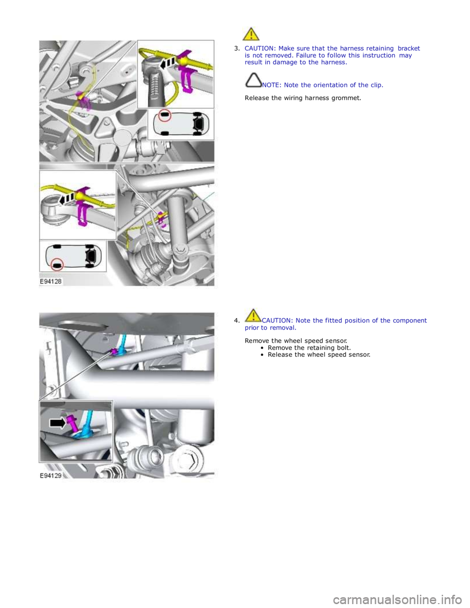
3. CAUTION: Make sure that the harness retaining bracket
is not removed. Failure to follow this instruction may
result in damage to the harness.
NOTE: Note the orientation of the clip.
Release the wiring harness grommet.
4. CAUTION: Note the fitted position of the component
prior to removal.
Remove the wheel speed sensor.
Remove the retaining bolt.
Release the wheel speed sensor.
Page 715 of 3039
Published: 11-May-2011
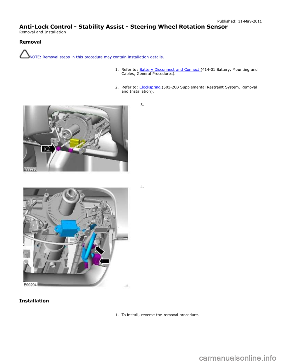
Anti-Lock Control - Stability Assist - Steering Wheel Rotation Sensor
Removal and Installation
Removal
NOTE: Removal steps in this procedure may contain installation details.
1. Refer to: Battery Disconnect and Connect (414-01 Battery, Mounting and Cables, General Procedures).
2. Refer to: Clockspring (501-20B Supplemental Restraint System, Removal and Installation).
3.
4.
Installation
1. To install, reverse the removal procedure.
Page 716 of 3039
Published: 11-May-2011
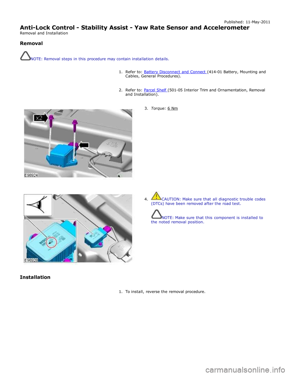
Anti-Lock Control - Stability Assist - Yaw Rate Sensor and Accelerometer
Removal and Installation
Removal
NOTE: Removal steps in this procedure may contain installation details.
1. Refer to: Battery Disconnect and Connect (414-01 Battery, Mounting and Cables, General Procedures).
2. Refer to: Parcel Shelf (501-05 Interior Trim and Ornamentation, Removal and Installation).
Installation
3. Torque: 6 Nm
4. CAUTION: Make sure that all diagnostic trouble codes
(DTCs) have been removed after the road test.
NOTE: Make sure that this component is installed to
the noted removal position.
1. To install, reverse the removal procedure.
Page 777 of 3039

Steering Column - Steering Column - Overview
Description and Operation
OVERVIEW Published: 11-May-2011
The steering column comprises the upper column assembly, the lower column assembly and the steering wheel. The 3
components are positively connected together to pass driver rotary input from the steering wheel to a linear output of the
steering rack.
The upper column assembly contains electrical adjustment for steering wheel reach and rake, the electric steering lock
mechanism and the steering angle sensor. Steering adjustment memory positions are stored in the driver's seat module.
The electric steering column is a standard fitment on all models. The upper column assembly contains electrical adjustment for
steering wheel reach and rake, the electric column lock mechanism and the steering angle sensor. Steering adjustment memory
positions are stored in the driver's seat module. The column also features a 'tilt away' function which moves the steering
column away from the driver allowing easier exit and entry to the vehicle.
Column adjustment is provided by a single motor for both reach and rake adjustment. Operation of the column adjustment is
controlled by a four way joystick type switch located in the column lower shroud. Column adjustment is an integral part of the
driver position memory system.
www.JagDocs.com
Page 780 of 3039
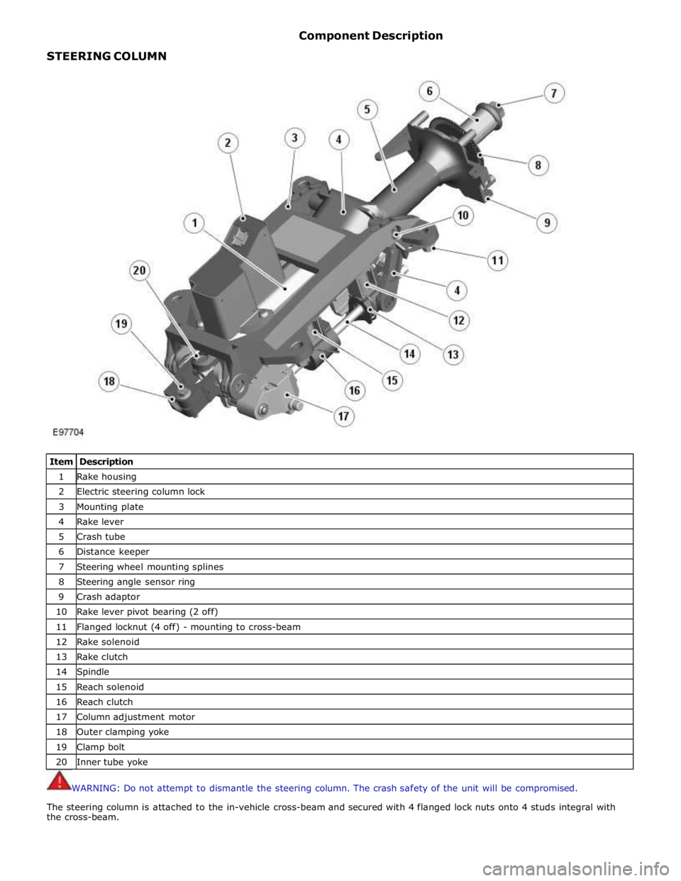
STEERING COLUMN Component Description
Item Description 1 Rake housing 2 Electric steering column lock 3 Mounting plate 4 Rake lever 5 Crash tube 6 Distance keeper 7 Steering wheel mounting splines 8 Steering angle sensor ring 9 Crash adaptor 10 Rake lever pivot bearing (2 off) 11 Flanged locknut (4 off) - mounting to cross-beam 12 Rake solenoid 13 Rake clutch 14 Spindle 15 Reach solenoid 16 Reach clutch 17 Column adjustment motor 18 Outer clamping yoke 19 Clamp bolt 20 Inner tube yoke
WARNING: Do not attempt to dismantle the steering column. The crash safety of the unit will be compromised.
The steering column is attached to the in-vehicle cross-beam and secured with 4 flanged lock nuts onto 4 studs integral with
the cross-beam.
Page 781 of 3039
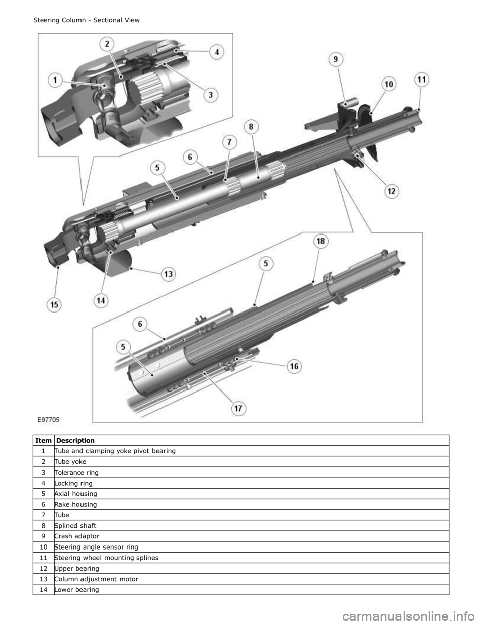
1 Tube and clamping yoke pivot bearing 2 Tube yoke 3 Tolerance ring 4 Locking ring 5 Axial housing 6 Rake housing 7 Tube 8 Splined shaft 9 Crash adaptor 10 Steering angle sensor ring 11 Steering wheel mounting splines 12 Upper bearing 13 Column adjustment motor 14 Lower bearing
Page 782 of 3039
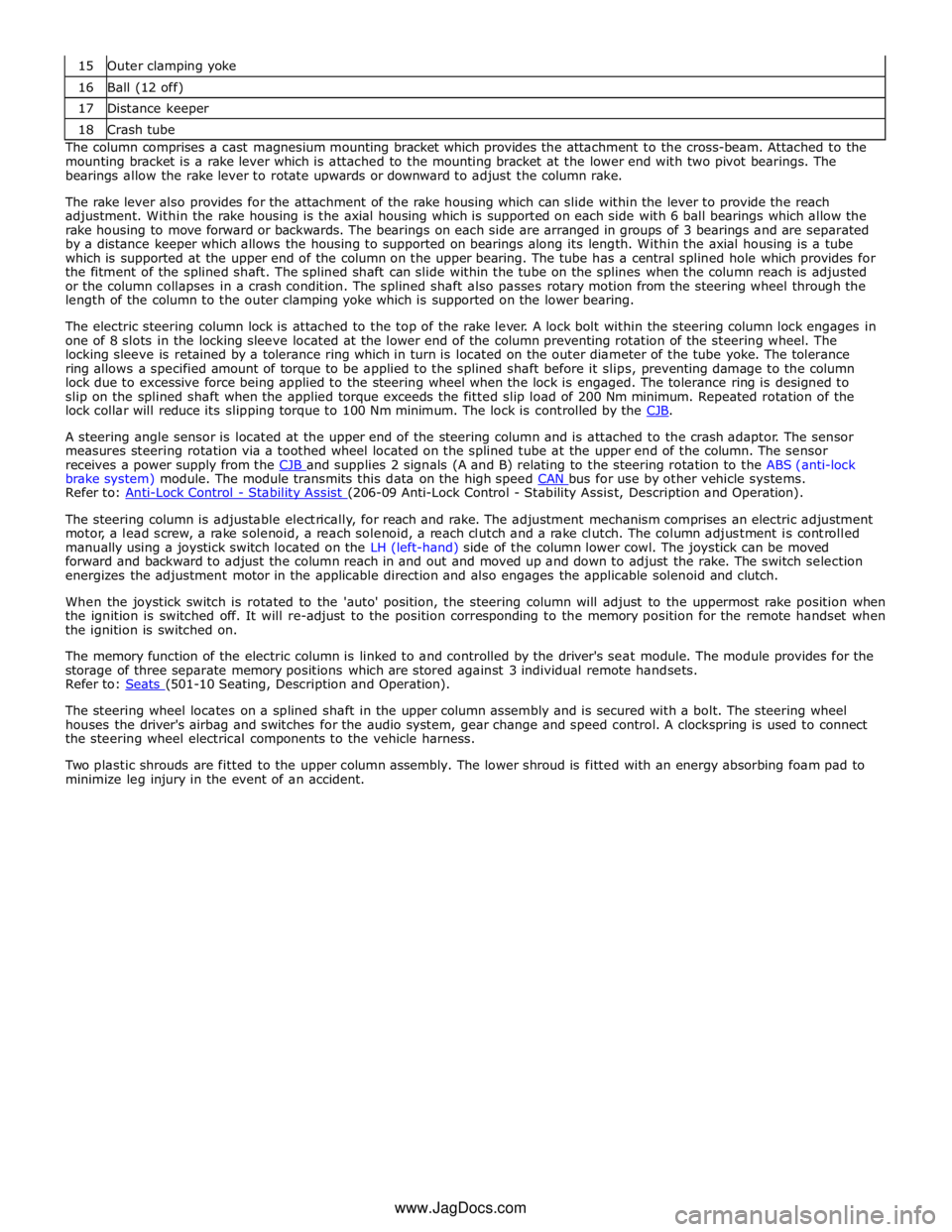
16 Ball (12 off) 17 Distance keeper 18 Crash tube The column comprises a cast magnesium mounting bracket which provides the attachment to the cross-beam. Attached to the
mounting bracket is a rake lever which is attached to the mounting bracket at the lower end with two pivot bearings. The
bearings allow the rake lever to rotate upwards or downward to adjust the column rake.
The rake lever also provides for the attachment of the rake housing which can slide within the lever to provide the reach
adjustment. Within the rake housing is the axial housing which is supported on each side with 6 ball bearings which allow the
rake housing to move forward or backwards. The bearings on each side are arranged in groups of 3 bearings and are separated
by a distance keeper which allows the housing to supported on bearings along its length. Within the axial housing is a tube
which is supported at the upper end of the column on the upper bearing. The tube has a central splined hole which provides for
the fitment of the splined shaft. The splined shaft can slide within the tube on the splines when the column reach is adjusted
or the column collapses in a crash condition. The splined shaft also passes rotary motion from the steering wheel through the
length of the column to the outer clamping yoke which is supported on the lower bearing.
The electric steering column lock is attached to the top of the rake lever. A lock bolt within the steering column lock engages in
one of 8 slots in the locking sleeve located at the lower end of the column preventing rotation of the steering wheel. The
locking sleeve is retained by a tolerance ring which in turn is located on the outer diameter of the tube yoke. The tolerance
ring allows a specified amount of torque to be applied to the splined shaft before it slips, preventing damage to the column
lock due to excessive force being applied to the steering wheel when the lock is engaged. The tolerance ring is designed to
slip on the splined shaft when the applied torque exceeds the fitted slip load of 200 Nm minimum. Repeated rotation of the
lock collar will reduce its slipping torque to 100 Nm minimum. The lock is controlled by the CJB.
A steering angle sensor is located at the upper end of the steering column and is attached to the crash adaptor. The sensor
measures steering rotation via a toothed wheel located on the splined tube at the upper end of the column. The sensor
receives a power supply from the CJB and supplies 2 signals (A and B) relating to the steering rotation to the ABS (anti-lock brake system) module. The module transmits this data on the high speed CAN bus for use by other vehicle systems. Refer to: Anti-Lock Control - Stability Assist (206-09 Anti-Lock Control - Stability Assist, Description and Operation).
The steering column is adjustable electrically, for reach and rake. The adjustment mechanism comprises an electric adjustment
motor, a lead screw, a rake solenoid, a reach solenoid, a reach clutch and a rake clutch. The column adjustment is controlled
manually using a joystick switch located on the LH (left-hand) side of the column lower cowl. The joystick can be moved
forward and backward to adjust the column reach in and out and moved up and down to adjust the rake. The switch selection
energizes the adjustment motor in the applicable direction and also engages the applicable solenoid and clutch.
When the joystick switch is rotated to the 'auto' position, the steering column will adjust to the uppermost rake position when
the ignition is switched off. It will re-adjust to the position corresponding to the memory position for the remote handset when
the ignition is switched on.
The memory function of the electric column is linked to and controlled by the driver's seat module. The module provides for the
storage of three separate memory positions which are stored against 3 individual remote handsets.
Refer to: Seats (501-10 Seating, Description and Operation).
The steering wheel locates on a splined shaft in the upper column assembly and is secured with a bolt. The steering wheel
houses the driver's airbag and switches for the audio system, gear change and speed control. A clockspring is used to connect
the steering wheel electrical components to the vehicle harness.
Two plastic shrouds are fitted to the upper column assembly. The lower shroud is fitted with an energy absorbing foam pad to
minimize leg injury in the event of an accident.
www.JagDocs.com