sensor JAGUAR XFR 2010 1.G Workshop Manual
[x] Cancel search | Manufacturer: JAGUAR, Model Year: 2010, Model line: XFR, Model: JAGUAR XFR 2010 1.GPages: 3039, PDF Size: 58.49 MB
Page 1185 of 3039

RH fuel rail. The FRP sensor is screwed into a threaded boss in the fuel rail. A flying lead and three pin connector provides the interface with the engine harness.
The FRP sensor contains a steel diaphragm fitted with strain gages, which are incorporated into a Wheatstone bridge. The output from the Wheatstone bridge is processed by the ECM to derive a pressure value.
FUEL INJECTORS
The fuel injectors spray fuel from the fuel rail directly into the combustion chambers. The fuel injectors are installed close to
the center of the combustion chambers, between the inlet and exhaust valves and next to the spark plug.
The fuel injectors are a push fit in the fuel rails and the cylinder heads. On each fuel injector, a rubber O-ring seals the head of
the fuel injector in the fuel rail. A teflon ring seals the nozzle of the fuel injector in the cylinder head. A clamp locks each fuel
injector to the fuel rail. FUEL RAIL PRESSURE SENSOR
Page 1187 of 3039
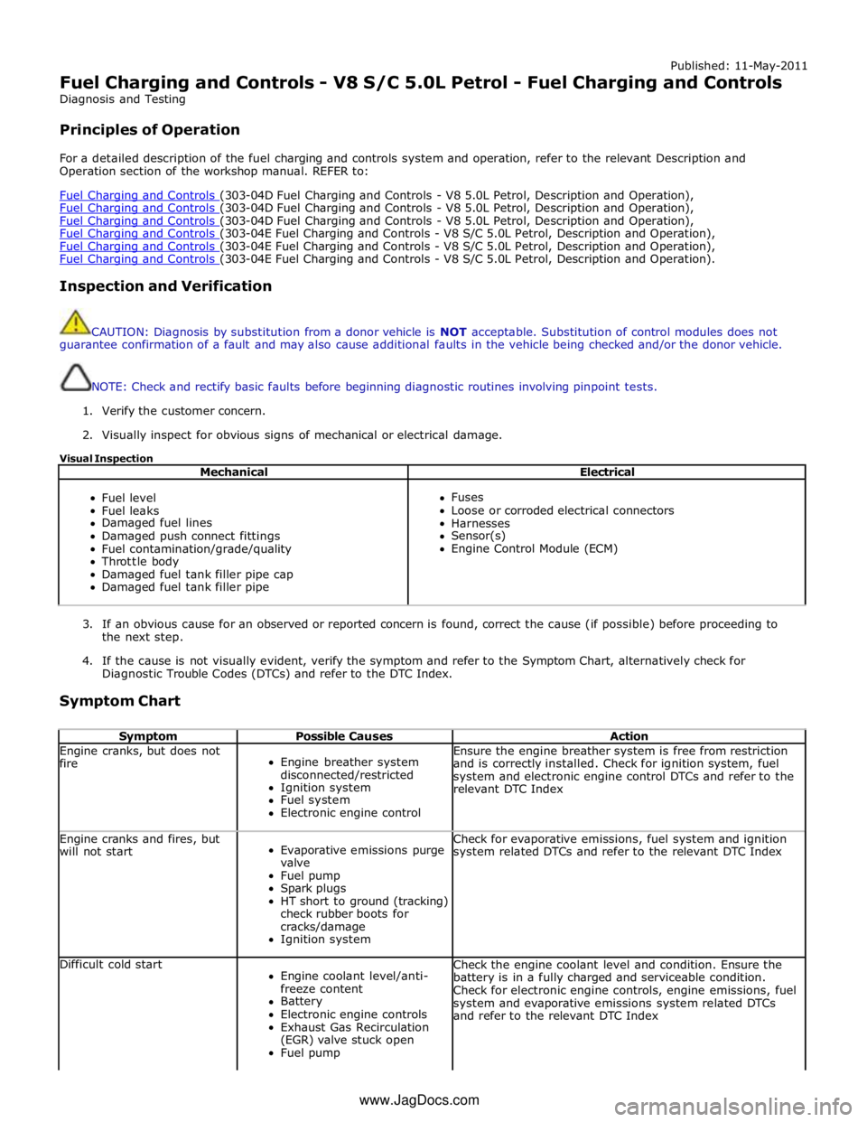
Published: 11-May-2011
Fuel Charging and Controls - V8 S/C 5.0L Petrol - Fuel Charging and Controls
Diagnosis and Testing
Principles of Operation
For a detailed description of the fuel charging and controls system and operation, refer to the relevant Description and
Operation section of the workshop manual. REFER to:
Fuel Charging and Controls (303-04D Fuel Charging and Controls - V8 5.0L Petrol, Description and Operation), Fuel Charging and Controls (303-04D Fuel Charging and Controls - V8 5.0L Petrol, Description and Operation), Fuel Charging and Controls (303-04D Fuel Charging and Controls - V8 5.0L Petrol, Description and Operation), Fuel Charging and Controls (303-04E Fuel Charging and Controls - V8 S/C 5.0L Petrol, Description and Operation), Fuel Charging and Controls (303-04E Fuel Charging and Controls - V8 S/C 5.0L Petrol, Description and Operation), Fuel Charging and Controls (303-04E Fuel Charging and Controls - V8 S/C 5.0L Petrol, Description and Operation).
Inspection and Verification
CAUTION: Diagnosis by substitution from a donor vehicle is NOT acceptable. Substitution of control modules does not
guarantee confirmation of a fault and may also cause additional faults in the vehicle being checked and/or the donor vehicle.
NOTE: Check and rectify basic faults before beginning diagnostic routines involving pinpoint tests.
1. Verify the customer concern.
2. Visually inspect for obvious signs of mechanical or electrical damage.
Visual Inspection
Mechanical Electrical
Fuel level
Fuel leaks
Damaged fuel lines
Damaged push connect fittings
Fuel contamination/grade/quality
Throttle body
Damaged fuel tank filler pipe cap
Damaged fuel tank filler pipe
Fuses
Loose or corroded electrical connectors
Harnesses
Sensor(s)
Engine Control Module (ECM)
3. If an obvious cause for an observed or reported concern is found, correct the cause (if possible) before proceeding to
the next step.
4. If the cause is not visually evident, verify the symptom and refer to the Symptom Chart, alternatively check for
Diagnostic Trouble Codes (DTCs) and refer to the DTC Index.
Symptom Chart
Symptom Possible Causes Action Engine cranks, but does not
fire
Engine breather system
disconnected/restricted
Ignition system
Fuel system
Electronic engine control Ensure the engine breather system is free from restriction
and is correctly installed. Check for ignition system, fuel
system and electronic engine control DTCs and refer to the
relevant DTC Index Engine cranks and fires, but
will not start
Evaporative emissions purge
valve
Fuel pump
Spark plugs
HT short to ground (tracking)
check rubber boots for
cracks/damage
Ignition system Check for evaporative emissions, fuel system and ignition
system related DTCs and refer to the relevant DTC Index Difficult cold start
Engine coolant level/anti-
freeze content
Battery
Electronic engine controls
Exhaust Gas Recirculation
(EGR) valve stuck open
Fuel pump Check the engine coolant level and condition. Ensure the
battery is in a fully charged and serviceable condition.
Check for electronic engine controls, engine emissions, fuel
system and evaporative emissions system related DTCs
and refer to the relevant DTC Index www.JagDocs.com
Page 1245 of 3039
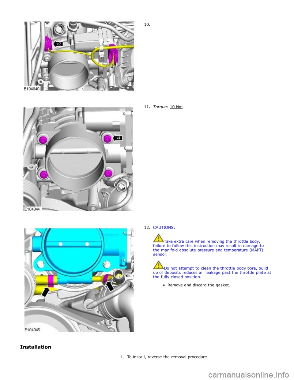
Installation
10.
11.
12.
Torque: 10 Nm
CAUTIONS:
Take extra care when removing the throttle body,
failure to follow this instruction may result in damage to
the manifold absolute pressure and temperature (MAPT)
sensor.
Do not attempt to clean the throttle body bore, build
up of deposits reduces air leakage past the throttle plate at
the fully closed position.
Remove and discard the gasket.
1. To install, reverse the removal procedure.
Page 1276 of 3039
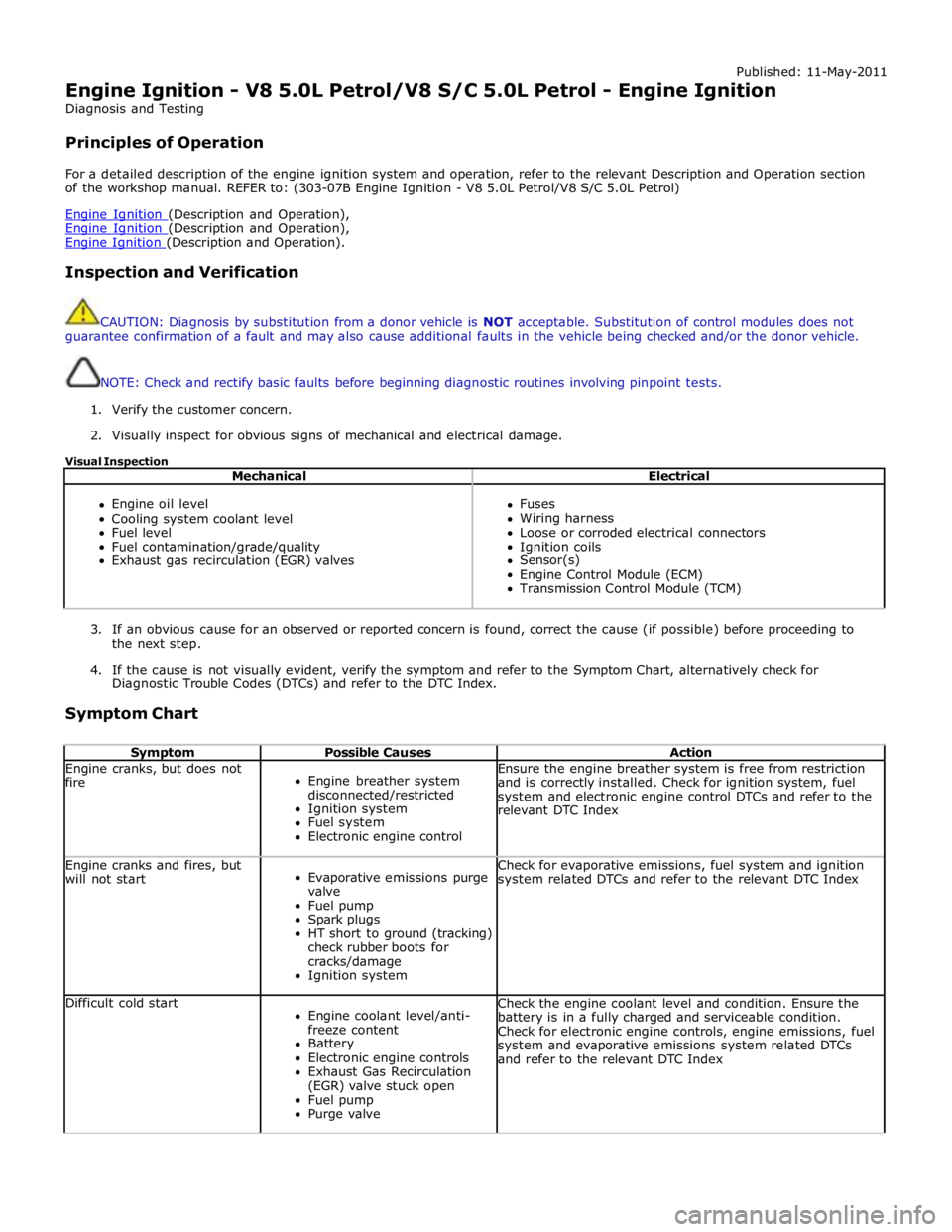
Published: 11-May-2011
Engine Ignition - V8 5.0L Petrol/V8 S/C 5.0L Petrol - Engine Ignition
Diagnosis and Testing
Principles of Operation
For a detailed description of the engine ignition system and operation, refer to the relevant Description and Operation section
of the workshop manual. REFER to: (303-07B Engine Ignition - V8 5.0L Petrol/V8 S/C 5.0L Petrol)
Engine Ignition (Description and Operation), Engine Ignition (Description and Operation), Engine Ignition (Description and Operation).
Inspection and Verification
CAUTION: Diagnosis by substitution from a donor vehicle is NOT acceptable. Substitution of control modules does not
guarantee confirmation of a fault and may also cause additional faults in the vehicle being checked and/or the donor vehicle.
NOTE: Check and rectify basic faults before beginning diagnostic routines involving pinpoint tests.
1. Verify the customer concern.
2. Visually inspect for obvious signs of mechanical and electrical damage.
Visual Inspection
Mechanical Electrical
Engine oil level
Cooling system coolant level
Fuel level
Fuel contamination/grade/quality
Exhaust gas recirculation (EGR) valves
Fuses
Wiring harness
Loose or corroded electrical connectors
Ignition coils
Sensor(s)
Engine Control Module (ECM)
Transmission Control Module (TCM)
3. If an obvious cause for an observed or reported concern is found, correct the cause (if possible) before proceeding to
the next step.
4. If the cause is not visually evident, verify the symptom and refer to the Symptom Chart, alternatively check for
Diagnostic Trouble Codes (DTCs) and refer to the DTC Index.
Symptom Chart
Symptom Possible Causes Action Engine cranks, but does not
fire
Engine breather system
disconnected/restricted
Ignition system
Fuel system
Electronic engine control Ensure the engine breather system is free from restriction
and is correctly installed. Check for ignition system, fuel
system and electronic engine control DTCs and refer to the
relevant DTC Index Engine cranks and fires, but
will not start
Evaporative emissions purge
valve
Fuel pump
Spark plugs
HT short to ground (tracking)
check rubber boots for
cracks/damage
Ignition system Check for evaporative emissions, fuel system and ignition
system related DTCs and refer to the relevant DTC Index Difficult cold start
Engine coolant level/anti-
freeze content
Battery
Electronic engine controls
Exhaust Gas Recirculation
(EGR) valve stuck open
Fuel pump
Purge valve Check the engine coolant level and condition. Ensure the
battery is in a fully charged and serviceable condition.
Check for electronic engine controls, engine emissions, fuel
system and evaporative emissions system related DTCs
and refer to the relevant DTC Index
Page 1283 of 3039
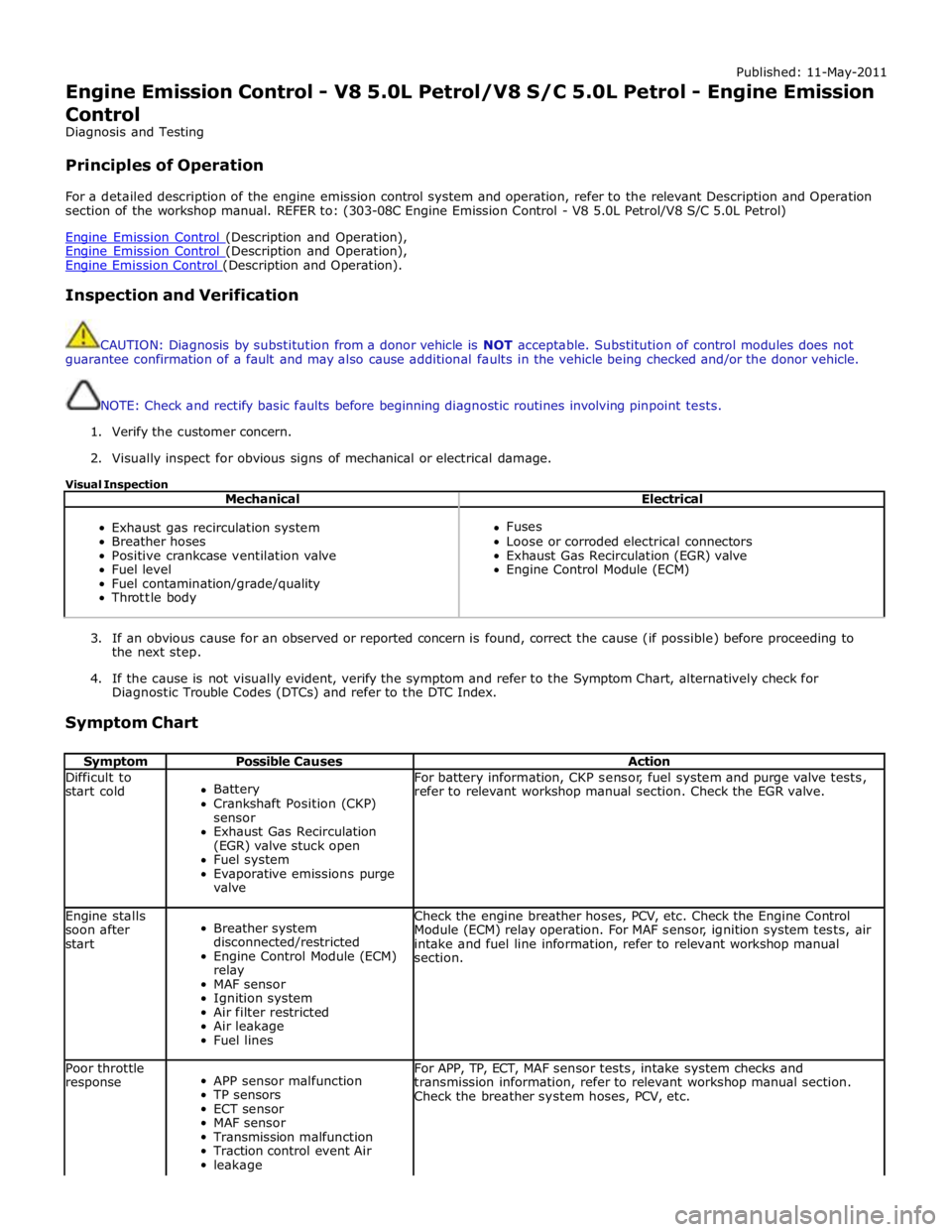
Published: 11-May-2011
Engine Emission Control - V8 5.0L Petrol/V8 S/C 5.0L Petrol - Engine Emission
Control
Diagnosis and Testing
Principles of Operation
For a detailed description of the engine emission control system and operation, refer to the relevant Description and Operation
section of the workshop manual. REFER to: (303-08C Engine Emission Control - V8 5.0L Petrol/V8 S/C 5.0L Petrol)
Engine Emission Control (Description and Operation), Engine Emission Control (Description and Operation), Engine Emission Control (Description and Operation).
Inspection and Verification
CAUTION: Diagnosis by substitution from a donor vehicle is NOT acceptable. Substitution of control modules does not
guarantee confirmation of a fault and may also cause additional faults in the vehicle being checked and/or the donor vehicle.
NOTE: Check and rectify basic faults before beginning diagnostic routines involving pinpoint tests.
1. Verify the customer concern.
2. Visually inspect for obvious signs of mechanical or electrical damage.
Visual Inspection
Mechanical Electrical
Exhaust gas recirculation system
Breather hoses
Positive crankcase ventilation valve
Fuel level
Fuel contamination/grade/quality
Throttle body
Fuses
Loose or corroded electrical connectors
Exhaust Gas Recirculation (EGR) valve
Engine Control Module (ECM)
3. If an obvious cause for an observed or reported concern is found, correct the cause (if possible) before proceeding to
the next step.
4. If the cause is not visually evident, verify the symptom and refer to the Symptom Chart, alternatively check for
Diagnostic Trouble Codes (DTCs) and refer to the DTC Index.
Symptom Chart
Symptom Possible Causes Action Difficult to
start cold
Battery
Crankshaft Position (CKP)
sensor
Exhaust Gas Recirculation
(EGR) valve stuck open
Fuel system
Evaporative emissions purge
valve For battery information, CKP sensor, fuel system and purge valve tests,
refer to relevant workshop manual section. Check the EGR valve. Engine stalls
soon after
start
Breather system
disconnected/restricted
Engine Control Module (ECM)
relay
MAF sensor
Ignition system
Air filter restricted
Air leakage
Fuel lines Check the engine breather hoses, PCV, etc. Check the Engine Control
Module (ECM) relay operation. For MAF sensor, ignition system tests, air
intake and fuel line information, refer to relevant workshop manual
section. Poor throttle
response
APP sensor malfunction
TP sensors
ECT sensor
MAF sensor
Transmission malfunction
Traction control event Air
leakage For APP, TP, ECT, MAF sensor tests, intake system checks and
transmission information, refer to relevant workshop manual section.
Check the breather system hoses, PCV, etc.
Page 1285 of 3039

Air cleaner retaining bolts 8 - 71 Supercharger retaining bolts 25 18 - Charge air cooler lower assembly retaining bolts 20 15 - Throttle body retaining studs 10 7 - Charge air cooler top assembly retaining bolts 25 18 - Manifold absolute pressure and temperature (MAPT) sensor 5 - 44 Coolant outlet pipe 11 8 -
Page 1292 of 3039
9 Support 10 Inlet connection 11 Outlet connection 12 MAFT sensor The outlet tubes and T-piece duct direct the air from the air cleaners to the electric throttle. Hose clamps connect the outlet
tubes and T-piece duct together, and to the air cleaners and the electric throttle. A grommet and bracket attached the T-piece
duct to a bracket on the RH cylinder head. The two outlet tubes and the T-piece duct each incorporate a quarter wave resonator to reduce air induction noise.
The LH (left-hand) outlet tube incorporates a connector stub for the engine full load breather pipe.
The T-piece duct incorporates a connector stub for the vacuum tube of the bypass valve actuator on the supercharger.
SUPERCHARGER AND INTAKE MANIFOLDS
The SC increases the pressure, and thus mass, of the air supplied to the engine, to increase the engine's power output. Two separate intake manifolds direct air from the SC to the cylinder inlet ports.
The intake manifolds are attached to their related cylinder heads and the sides of the SC. Two dowels locate the SC in position on the cylinder block. A charge air cooler tank top is installed on top of the SC and intake manifolds to form the air duct from the SC outlet to the intake manifolds. A charge air cooler is installed in each intake manifold.
The charge air cooler tank top incorporates four studs for the attachment of the engine cover. A NVH (noise, vibration and
harshness) pad is attached to the side of each intake manifold.
Page 1293 of 3039
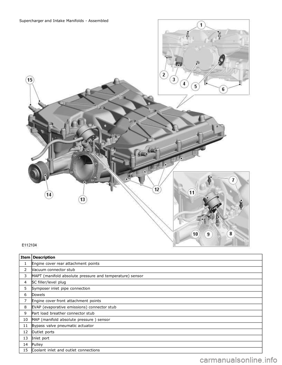
1 Engine cover rear attachment points 2 Vacuum connector stub 3 MAPT (manifold absolute pressure and temperature) sensor 4 SC filler/level plug 5 Symposer inlet pipe connection 6 Dowels 7 Engine cover front attachment points 8 EVAP (evaporative emissions) connector stub 9 Part load breather connector stub 10 MAP (manifold absolute pressure ) sensor 11 Bypass valve pneumatic actuator 12 Outlet ports 13 Inlet port 14 Pulley 15 Coolant inlet and outlet connections Supercharger and Intake Manifolds - Assembled
Page 1295 of 3039
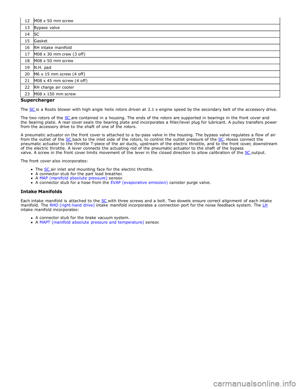
13 Bypass valve 14 SC 15 Gasket 16 RH intake manifold 17 M08 x 30 mm crew (3 off) 18 M08 x 50 mm screw 19 N.H. pad 20 M6 x 15 mm screw (4 off) 21 M08 x 45 mm screw (4 off) 22 RH charge air cooler 23 M08 x 150 mm screw Supercharger
The SC is a Roots blower with high angle helix rotors driven at 2.1 x engine speed by the secondary belt of the accessory drive.
The two rotors of the SC are contained in a housing. The ends of the rotors are supported in bearings in the front cover and the bearing plate. A rear cover seals the bearing plate and incorporates a filler/level plug for lubricant. A pulley transfers power
from the accessory drive to the shaft of one of the rotors.
A pneumatic actuator on the front cover is attached to a by-pass valve in the housing. The bypass valve regulates a flow of air
from the outlet of the SC back to the inlet side of the rotors, to control the outlet pressure of the SC. Hoses connect the pneumatic actuator to the throttle T-piece of the air ducts, upstream of the electric throttle, and to the front cover, downstream
of the electric throttle. A lever connects the actuating rod of the pneumatic actuator to the shaft of the bypass
valve. A screw in the front cover limits movement of the lever in the closed direction to allow calibration of the SC output. The front cover also incorporates:
The SC air inlet and mounting face for the electric throttle. A connector stub for the part load breather.
A MAP (manifold absolute pressure) sensor.
A connector stub for a hose from the EVAP (evaporative emission) canister purge valve.
Intake Manifolds
Each intake manifold is attached to the SC with three screws and a bolt. Two dowels ensure correct alignment of each intake manifold. The RHD (right-hand drive) intake manifold incorporates a connection port for the noise feedback system. The LH intake manifold incorporates:
A connector stub for the brake vacuum system.
A MAPT (manifold absolute pressure and temperature) sensor.
Page 1299 of 3039
Published: 11-May-2011
Intake Air Distribution and Filtering - V8 S/C 5.0L Petrol - Intake Air
Distribution and Filtering
Diagnosis and Testing
Principles of Operation
For a detailed description of the intake air distribution and filtering system and operation, refer to the relevant Description and
Operation section of the workshop manual. REFER to: (303-12D Intake Air Distribution and Filtering - V8 S/C 5.0L Petrol)
Intake Air Distribution and Filtering (Description and Operation), Intake Air Distribution and Filtering (Description and Operation), Intake Air Distribution and Filtering (Description and Operation).
Inspection and Verification
CAUTION: Diagnosis by substitution from a donor vehicle is NOT acceptable. Substitution of control modules does not
guarantee confirmation of a fault and may also cause additional faults in the vehicle being checked and/or the donor vehicle.
NOTE: Check and rectify basic faults before beginning diagnostic routines involving pinpoint tests.
1. Verify the customer concern.
2. Visually inspect for obvious signs of mechanical or electrical damage.
Visual Inspection
Mechanical Electrical
Hoses and ducts (damage/connections)
Air cleaner element (contaminated/blocked)
Restricted air intake
Supercharger
Supercharger (cooling fan) drive belt
Supercharger seals and gaskets
Charge air coolers (damage/connection)
Mass Air Flow (MAF) sensor
Manifold Absolute Pressure (MAP) sensor
Manifold Absolute Pressure/Temperature (MAPT) sensor
Throttle body
Harness (security/damage)
Connections (security/damage)
3. If an obvious cause for an observed or reported concern is found, correct the cause (if possible) before proceeding to
the next step.
4. If the cause is not visually evident, verify the symptom and refer to the Symptom Chart, alternatively check for
Diagnostic Trouble Codes (DTCs) and refer to the DTC Index.
Symptom Chart
Symptom Possible Causes Action Vehicle does not
start/hard
starting/poor
performance
Restricted/Blocked air intake
Restricted/Blocked air
cleaner element Clear the restriction. Replace the air cleaner element as necessary.
Refer to the relevant workshop manual section. Excessive intake
noise
Intake pipe
disconnected/damaged after
the air cleaner
Air cleaner assembly
incorrectly
assembled/damaged Check the intake system and hoses for correct installation/damage.
Refer to the relevant workshop manual section. Lack of boost
Supercharger drive belt
broken/slipping
Supercharger fault
Supercharger air intake fault
Major air leakage (after the
supercharger) Check the supercharger and drive belt. Check the charge air coolers.
Refer to the relevant workshop manual section. Noise
Supercharger drive belt
slipping
Supercharger fault
Major air leakage (after the
supercharger) Check the supercharger and drive belt. Remove the supercharger drive
belt and recheck for noise. Turn the supercharger by hand and check
for excessive resistance. Check for excessive play at the supercharger
pulley. Check the charge air coolers. Refer to the relevant workshop
manual section.