Control module JAGUAR XFR 2010 1.G Workshop Manual
[x] Cancel search | Manufacturer: JAGUAR, Model Year: 2010, Model line: XFR, Model: JAGUAR XFR 2010 1.GPages: 3039, PDF Size: 58.49 MB
Page 467 of 3039
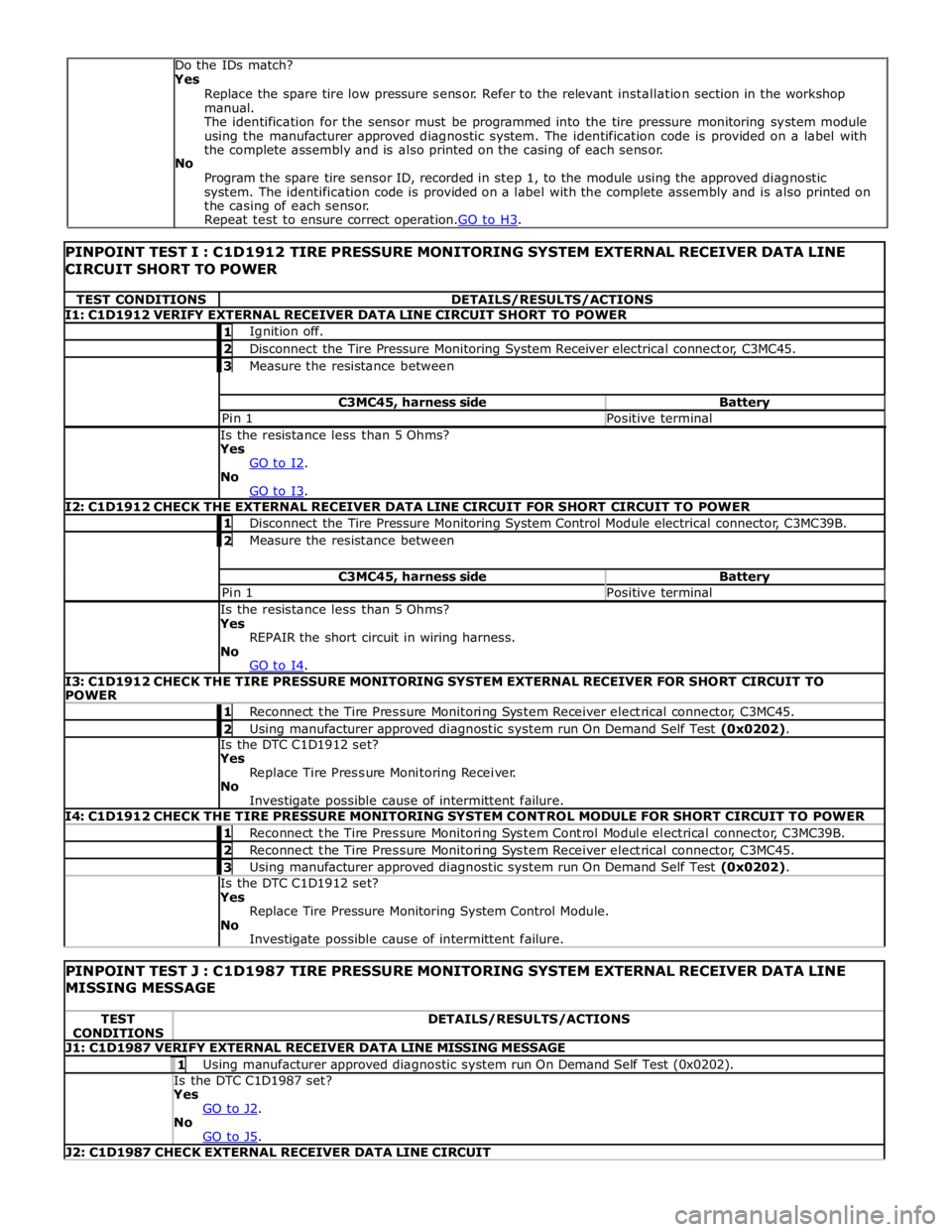
TEST CONDITIONS DETAILS/RESULTS/ACTIONS I1: C1D1912 VERIFY EXTERNAL RECEIVER DATA LINE CIRCUIT SHORT TO POWER 1 Ignition off. 2 Disconnect the Tire Pressure Monitoring System Receiver electrical connector, C3MC45. 3 Measure the resistance between C3MC45, harness side Battery Pin 1 Positive terminal Is the resistance less than 5 Ohms?
Yes
GO to I2. No
GO to I3. I2: C1D1912 CHECK THE EXTERNAL RECEIVER DATA LINE CIRCUIT FOR SHORT CIRCUIT TO POWER 1 Disconnect the Tire Pressure Monitoring System Control Module electrical connector, C3MC39B. 2 Measure the resistance between C3MC45, harness side Battery Pin 1 Positive terminal Is the resistance less than 5 Ohms?
Yes
REPAIR the short circuit in wiring harness.
No
GO to I4. I3: C1D1912 CHECK THE TIRE PRESSURE MONITORING SYSTEM EXTERNAL RECEIVER FOR SHORT CIRCUIT TO
POWER 1 Reconnect the Tire Pressure Monitoring System Receiver electrical connector, C3MC45. 2 Using manufacturer approved diagnostic system run On Demand Self Test (0x0202). Is the DTC C1D1912 set?
Yes
Replace Tire Pressure Monitoring Receiver.
No
Investigate possible cause of intermittent failure. I4: C1D1912 CHECK THE TIRE PRESSURE MONITORING SYSTEM CONTROL MODULE FOR SHORT CIRCUIT TO POWER 1 Reconnect the Tire Pressure Monitoring System Control Module electrical connector, C3MC39B. 2 Reconnect the Tire Pressure Monitoring System Receiver electrical connector, C3MC45. 3 Using manufacturer approved diagnostic system run On Demand Self Test (0x0202). Is the DTC C1D1912 set?
Yes
Replace Tire Pressure Monitoring System Control Module.
No
Investigate possible cause of intermittent failure.
PINPOINT TEST J : C1D1987 TIRE PRESSURE MONITORING SYSTEM EXTERNAL RECEIVER DATA LINE
MISSING MESSAGE TEST
CONDITIONS DETAILS/RESULTS/ACTIONS J1: C1D1987 VERIFY EXTERNAL RECEIVER DATA LINE MISSING MESSAGE 1 Using manufacturer approved diagnostic system run On Demand Self Test (0x0202). Is the DTC C1D1987 set? Yes
GO to J2. No
GO to J5. J2: C1D1987 CHECK EXTERNAL RECEIVER DATA LINE CIRCUIT Do the IDs match?
Yes
Replace the spare tire low pressure sensor. Refer to the relevant installation section in the workshop
manual.
The identification for the sensor must be programmed into the tire pressure monitoring system module
using the manufacturer approved diagnostic system. The identification code is provided on a label with
the complete assembly and is also printed on the casing of each sensor.
No
Program the spare tire sensor ID, recorded in step 1, to the module using the approved diagnostic
system. The identification code is provided on a label with the complete assembly and is also printed on
the casing of each sensor.
Repeat test to ensure correct operation.GO to H3.
Page 468 of 3039
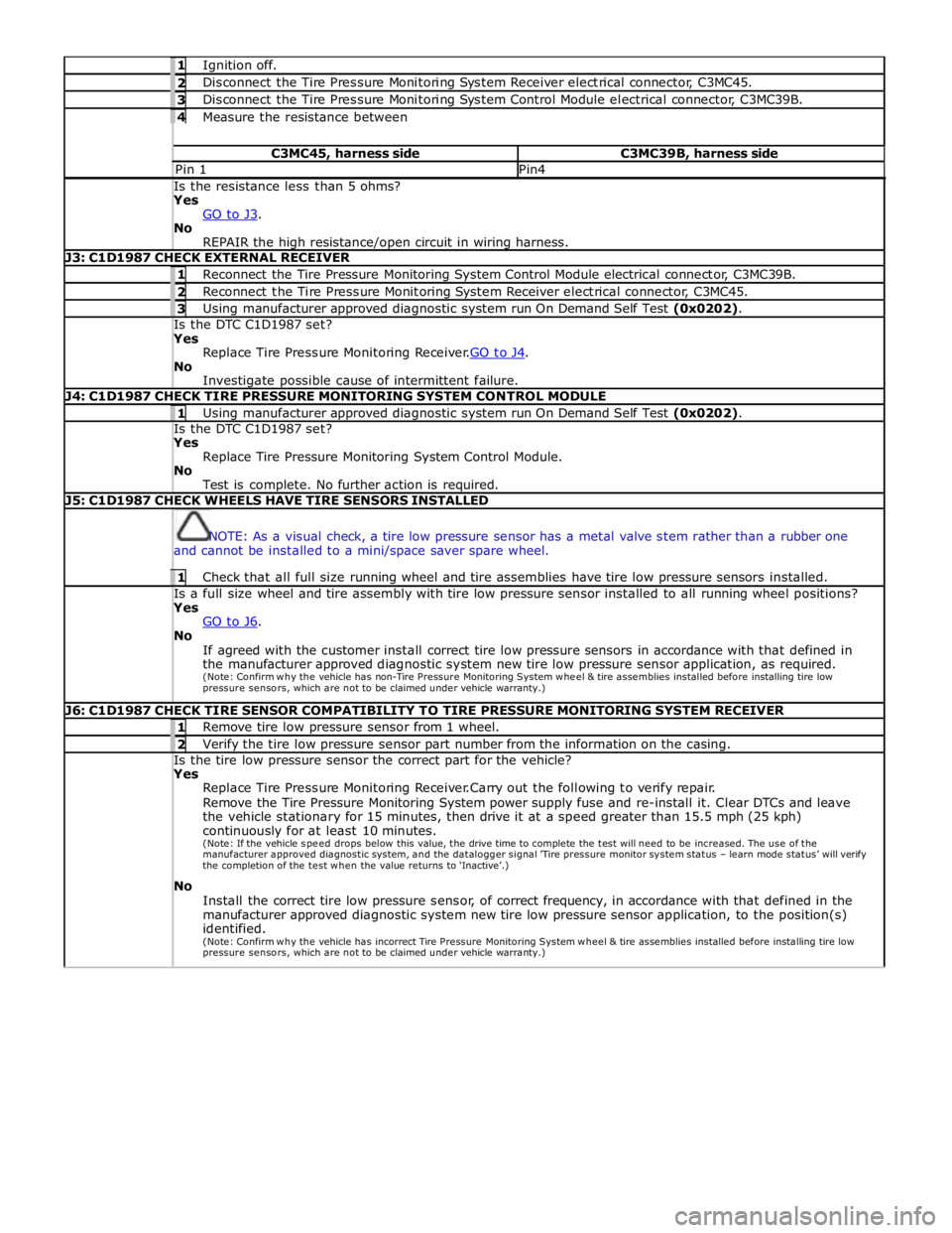
1 Ignition off. 2 Disconnect the Tire Pressure Monitoring System Receiver electrical connector, C3MC45. 3 Disconnect the Tire Pressure Monitoring System Control Module electrical connector, C3MC39B. 4 Measure the resistance between C3MC45, harness side C3MC39B, harness side Pin 1 Pin4 Is the resistance less than 5 ohms? Yes
GO to J3. No
REPAIR the high resistance/open circuit in wiring harness. J3: C1D1987 CHECK EXTERNAL RECEIVER 1 Reconnect the Tire Pressure Monitoring System Control Module electrical connector, C3MC39B. 2 Reconnect the Tire Pressure Monitoring System Receiver electrical connector, C3MC45. 3 Using manufacturer approved diagnostic system run On Demand Self Test (0x0202). Is the DTC C1D1987 set? Yes
Replace Tire Pressure Monitoring Receiver.GO to J4. No
Investigate possible cause of intermittent failure. J4: C1D1987 CHECK TIRE PRESSURE MONITORING SYSTEM CONTROL MODULE 1 Using manufacturer approved diagnostic system run On Demand Self Test (0x0202). Is the DTC C1D1987 set? Yes
Replace Tire Pressure Monitoring System Control Module.
No
Test is complete. No further action is required. J5: C1D1987 CHECK WHEELS HAVE TIRE SENSORS INSTALLED
NOTE: As a visual check, a tire low pressure sensor has a metal valve stem rather than a rubber one
and cannot be installed to a mini/space saver spare wheel. 1 Check that all full size running wheel and tire assemblies have tire low pressure sensors installed. Is a full size wheel and tire assembly with tire low pressure sensor installed to all running wheel positions? Yes
GO to J6. No
If agreed with the customer install correct tire low pressure sensors in accordance with that defined in
the manufacturer approved diagnostic system new tire low pressure sensor application, as required.
(Note: Confirm why the vehicle has non-Tire Pressure Monitoring System w he e l & tire assemblies installed before installing tire low
pressure sensors, which are not to be claimed under vehicle warranty.) J6: C1D1987 CHECK TIRE SENSOR COMPATIBILITY TO TIRE PRESSURE MONITORING SYSTEM RECEIVER 1 Remove tire low pressure sensor from 1 wheel. 2 Verify the tire low pressure sensor part number from the information on the casing. Is the tire low pressure sensor the correct part for the vehicle? Yes
Replace Tire Pressure Monitoring Receiver.Carry out the following to verify repair.
Remove the Tire Pressure Monitoring System power supply fuse and re-install it. Clear DTCs and leave
the vehicle stationary for 15 minutes, then drive it at a speed greater than 15.5 mph (25 kph)
continuously for at least 10 minutes.
(Note: If the vehicle spe e d drops below this value, the drive time to complete the test will need to be increased. The use of the manufacturer approved diagnostic system, and the datalogger signal ’Tire pressure monitor system status – learn mode status’ will verify the completion of the test w he n the value returns to ‘Inactive’.)
No
Install the correct tire low pressure sensor, of correct frequency, in accordance with that defined in the
manufacturer approved diagnostic system new tire low pressure sensor application, to the position(s)
identified.
(Note: Confirm why the vehicle has incorrect Tire Pressure Monitoring System w he e l & tire assemblies installed before installing tire low
pressure sensors, which are not to be claimed under vehicle warranty.)
Page 481 of 3039

Published: 11-May-2011
Vehicle Dynamic Suspension - Vehicle Dynamic Suspension V8 5.0L Petrol/V8 S/C 5.0L Petrol - Overview
Description and Operation
OVERVIEW
Adaptive Dynamics - Supercharged Vehicles from 2010MY
The adaptive dynamics system, is an electronically controlled suspension system which constantly adjusts the damping
characteristics of the suspension dampers in reaction to the existing driving conditions. The adaptive dynamics system is
available on specified models.
The system is controlled by an Adaptive Damping Module (ADM), located beneath the right-hand front seat. The module
receives signals from three dedicated vertical accelerometers; two at the front of the vehicle and one at the rear, which,
together with four suspension height sensors, determine the state of the body and wheel motions. In addition to these inputs,
further signals from other vehicle electronic system components to determine vehicle state and driver inputs are monitored by
the adaptive damping module. These combined signals are used by the adaptive damping module to continuously adjust the
damping characteristics of each of the suspension dampers in reaction to the current driving conditions to give the optimum
body control and vehicle ride.
Page 482 of 3039
Published: 11-May-2011
Vehicle Dynamic Suspension - Vehicle Dynamic Suspension V8 5.0L Petrol/V8 S/C 5.0L Petrol - System Operation and Component Description
Description and Operation
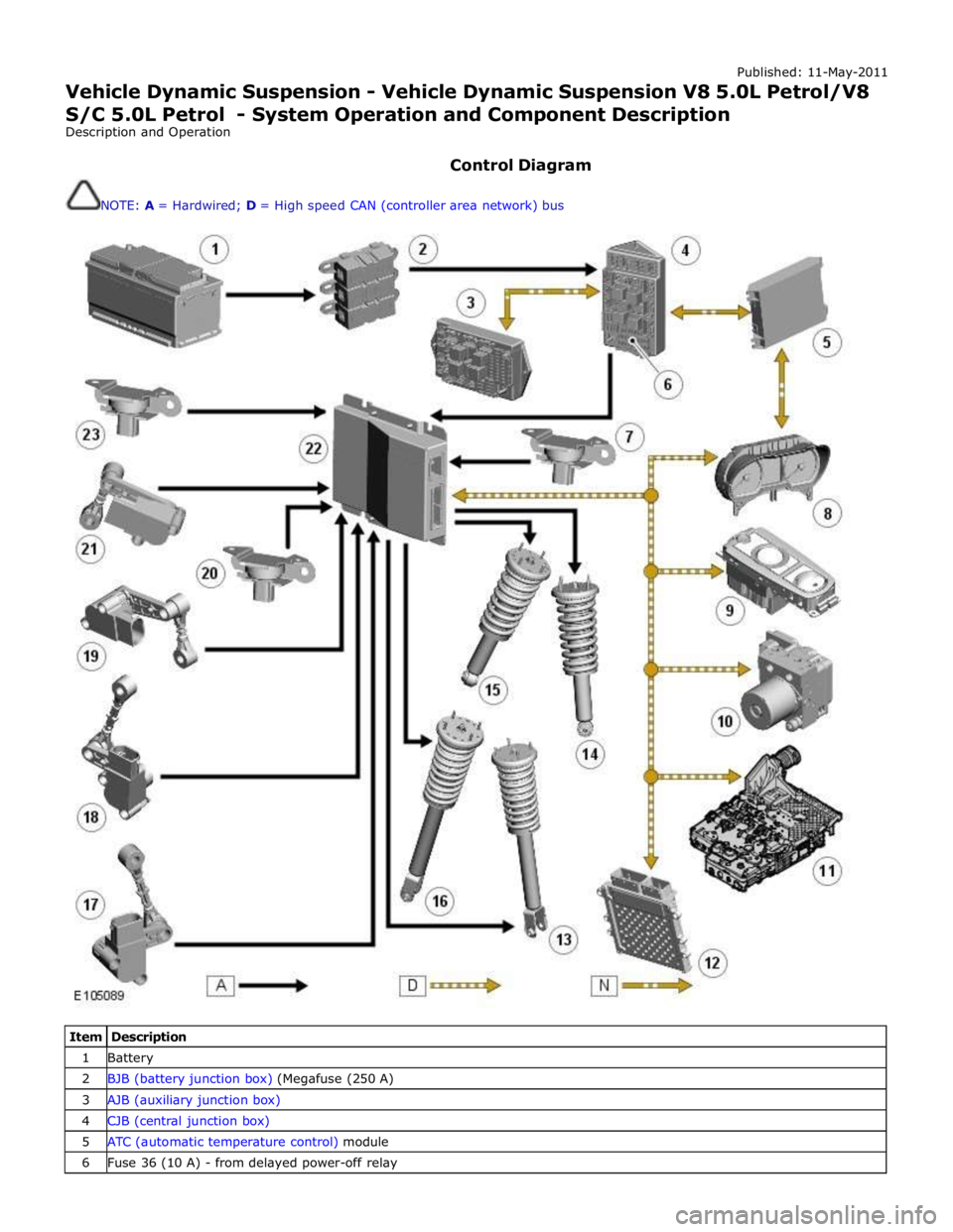
Control Diagram
NOTE: A = Hardwired; D = High speed CAN (controller area network) bus
Item Description 1 Battery 2 BJB (battery junction box) (Megafuse (250 A) 3 AJB (auxiliary junction box) 4 CJB (central junction box) 5 ATC (automatic temperature control) module 6 Fuse 36 (10 A) - from delayed power-off relay
Page 483 of 3039
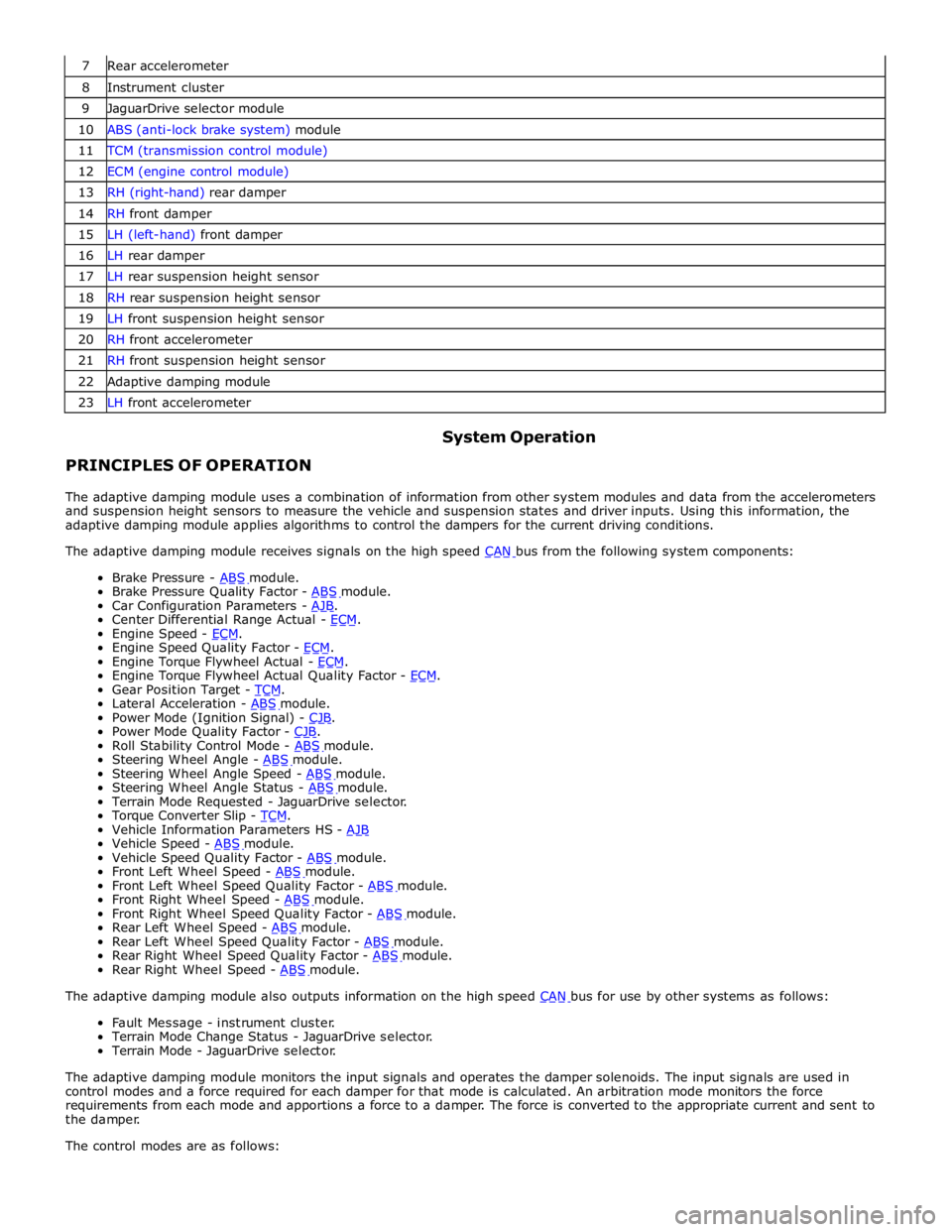
7 Rear accelerometer 8 Instrument cluster 9 JaguarDrive selector module 10 ABS (anti-lock brake system) module 11 TCM (transmission control module) 12 ECM (engine control module) 13 RH (right-hand) rear damper 14 RH front damper 15 LH (left-hand) front damper 16 LH rear damper 17 LH rear suspension height sensor 18 RH rear suspension height sensor 19 LH front suspension height sensor 20 RH front accelerometer 21 RH front suspension height sensor 22 Adaptive damping module 23 LH front accelerometer
PRINCIPLES OF OPERATION System Operation
The adaptive damping module uses a combination of information from other system modules and data from the accelerometers
and suspension height sensors to measure the vehicle and suspension states and driver inputs. Using this information, the
adaptive damping module applies algorithms to control the dampers for the current driving conditions.
The adaptive damping module receives signals on the high speed CAN bus from the following system components: Brake Pressure - ABS module. Brake Pressure Quality Factor - ABS module. Car Configuration Parameters - AJB. Center Differential Range Actual - ECM. Engine Speed - ECM. Engine Speed Quality Factor - ECM. Engine Torque Flywheel Actual - ECM. Engine Torque Flywheel Actual Quality Factor - ECM. Gear Position Target - TCM. Lateral Acceleration - ABS module. Power Mode (Ignition Signal) - CJB. Power Mode Quality Factor - CJB. Roll Stability Control Mode - ABS module. Steering Wheel Angle - ABS module. Steering Wheel Angle Speed - ABS module. Steering Wheel Angle Status - ABS module. Terrain Mode Requested - JaguarDrive selector.
Torque Converter Slip - TCM. Vehicle Information Parameters HS - AJB Vehicle Speed - ABS module. Vehicle Speed Quality Factor - ABS module. Front Left Wheel Speed - ABS module. Front Left Wheel Speed Quality Factor - ABS module. Front Right Wheel Speed - ABS module. Front Right Wheel Speed Quality Factor - ABS module. Rear Left Wheel Speed - ABS module. Rear Left Wheel Speed Quality Factor - ABS module. Rear Right Wheel Speed Quality Factor - ABS module. Rear Right Wheel Speed - ABS module. The adaptive damping module also outputs information on the high speed CAN bus for use by other systems as follows: Fault Message - instrument cluster.
Terrain Mode Change Status - JaguarDrive selector.
Terrain Mode - JaguarDrive selector.
The adaptive damping module monitors the input signals and operates the damper solenoids. The input signals are used in
control modes and a force required for each damper for that mode is calculated. An arbitration mode monitors the force
requirements from each mode and apportions a force to a damper. The force is converted to the appropriate current and sent to
the damper.
The control modes are as follows:
Page 484 of 3039
each damper to the appropriate level to maintain a flat and level body.
Roll Rate Control – Uses CAN inputs. Predicts vehicle roll rate due to driver steering inputs 100 times a second and increases damping to reduce roll rate.
Pitch Rate Control – Uses CAN inputs. Predicts vehicle pitch rate due to driver throttle and braking inputs 100 times a second and increases damping to reduce pitch rate.
Bump Rebound Control – Uses suspension height sensor and CAN inputs. Monitors the position of the wheel 500 times a second and increases the damping rate as the damper approaches the end of its travel.
Wheel Hop Control – Uses suspension height sensor and CAN inputs. Monitors the position of the wheel 500 times a second and detects when the wheel is at its natural frequency and increases the dampingto reduce vertical wheel
motion.
Under normal road conditions when the vehicle is stationary with the engine running, the dampers are set to the firm condition
to reduce power consumption.
The adaptive damping module receives its power supply via a relay and fuse in the CJB. The relay remains energized for a period of time after the ignition is off. This allows the adaptive damping module to record and store any DTC (diagnostic
trouble code) relating to adaptive dynamics system faults.
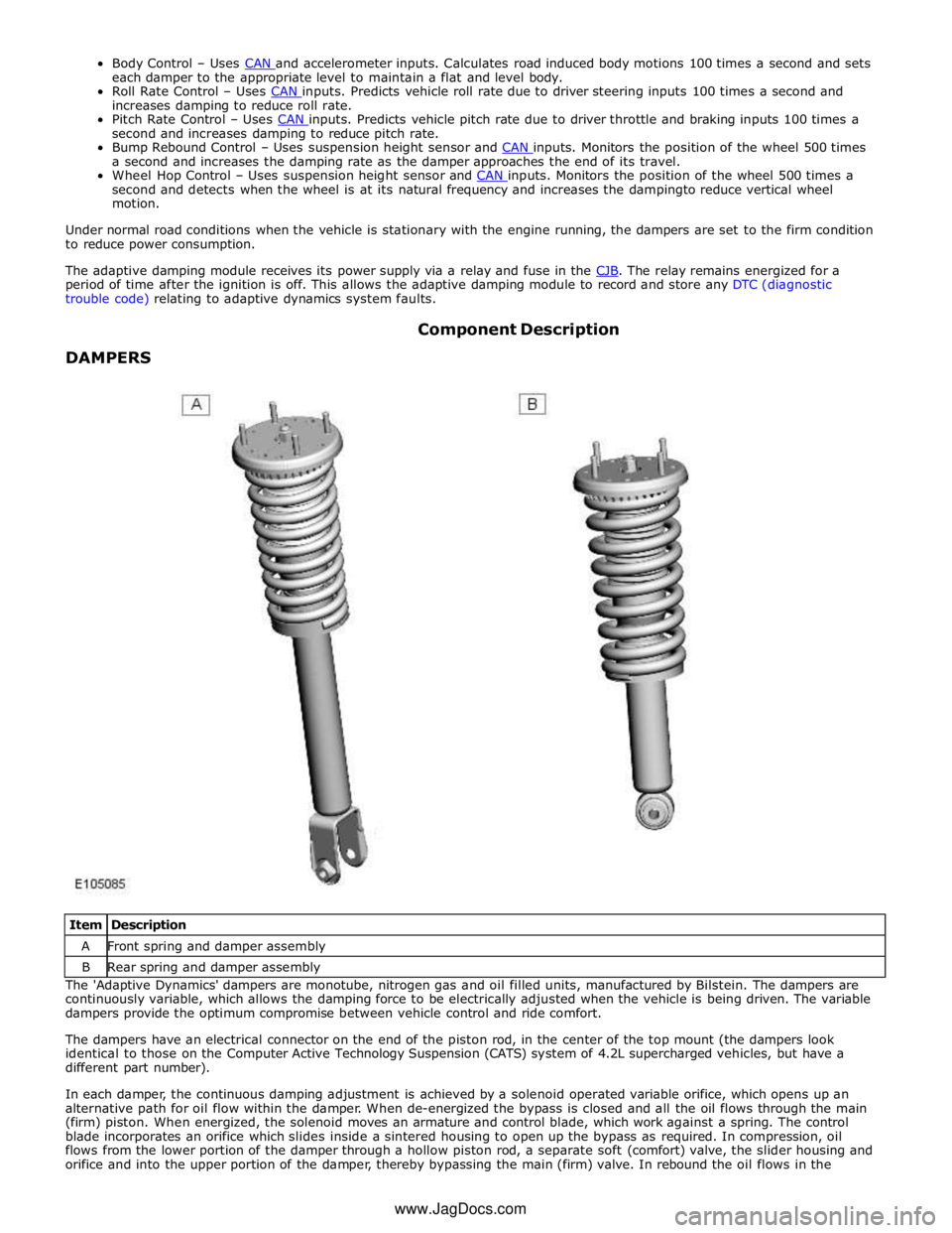
DAMPERS Component Description
Item Description A Front spring and damper assembly B Rear spring and damper assembly The 'Adaptive Dynamics' dampers are monotube, nitrogen gas and oil filled units, manufactured by Bilstein. The dampers are
continuously variable, which allows the damping force to be electrically adjusted when the vehicle is being driven. The variable
dampers provide the optimum compromise between vehicle control and ride comfort.
The dampers have an electrical connector on the end of the piston rod, in the center of the top mount (the dampers look
identical to those on the Computer Active Technology Suspension (CATS) system of 4.2L supercharged vehicles, but have a
different part number).
In each damper, the continuous damping adjustment is achieved by a solenoid operated variable orifice, which opens up an
alternative path for oil flow within the damper. When de-energized the bypass is closed and all the oil flows through the main
(firm) piston. When energized, the solenoid moves an armature and control blade, which work against a spring. The control
blade incorporates an orifice which slides inside a sintered housing to open up the bypass as required. In compression, oil
flows from the lower portion of the damper through a hollow piston rod, a separate soft (comfort) valve, the slider housing and
orifice and into the upper portion of the damper, thereby bypassing the main (firm) valve. In rebound the oil flows in the www.JagDocs.com
Page 486 of 3039
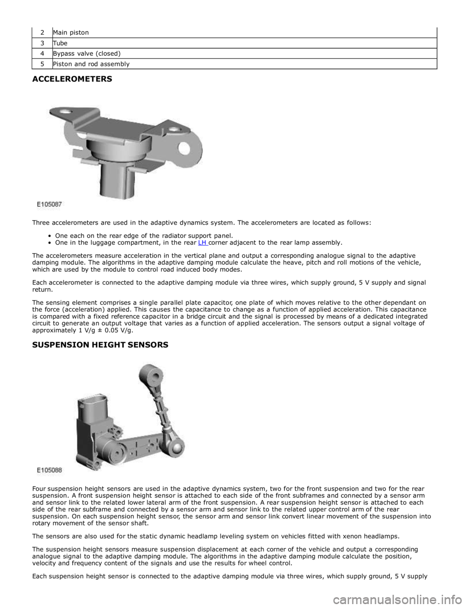
2 Main piston 3 Tube 4 Bypass valve (closed) 5 Piston and rod assembly ACCELEROMETERS
Three accelerometers are used in the adaptive dynamics system. The accelerometers are located as follows:
One each on the rear edge of the radiator support panel.
One in the luggage compartment, in the rear LH corner adjacent to the rear lamp assembly.
The accelerometers measure acceleration in the vertical plane and output a corresponding analogue signal to the adaptive
damping module. The algorithms in the adaptive damping module calculate the heave, pitch and roll motions of the vehicle,
which are used by the module to control road induced body modes.
Each accelerometer is connected to the adaptive damping module via three wires, which supply ground, 5 V supply and signal
return.
The sensing element comprises a single parallel plate capacitor, one plate of which moves relative to the other dependant on
the force (acceleration) applied. This causes the capacitance to change as a function of applied acceleration. This capacitance
is compared with a fixed reference capacitor in a bridge circuit and the signal is processed by means of a dedicated integrated
circuit to generate an output voltage that varies as a function of applied acceleration. The sensors output a signal voltage of
approximately 1 V/g ± 0.05 V/g.
SUSPENSION HEIGHT SENSORS
Four suspension height sensors are used in the adaptive dynamics system, two for the front suspension and two for the rear
suspension. A front suspension height sensor is attached to each side of the front subframes and connected by a sensor arm
and sensor link to the related lower lateral arm of the front suspension. A rear suspension height sensor is attached to each
side of the rear subframe and connected by a sensor arm and sensor link to the related upper control arm of the rear
suspension. On each suspension height sensor, the sensor arm and sensor link convert linear movement of the suspension into
rotary movement of the sensor shaft.
The sensors are also used for the static dynamic headlamp leveling system on vehicles fitted with xenon headlamps.
The suspension height sensors measure suspension displacement at each corner of the vehicle and output a corresponding
analogue signal to the adaptive damping module. The algorithms in the adaptive damping module calculate the position,
velocity and frequency content of the signals and use the results for wheel control.
Each suspension height sensor is connected to the adaptive damping module via three wires, which supply ground, 5 V supply
Page 487 of 3039
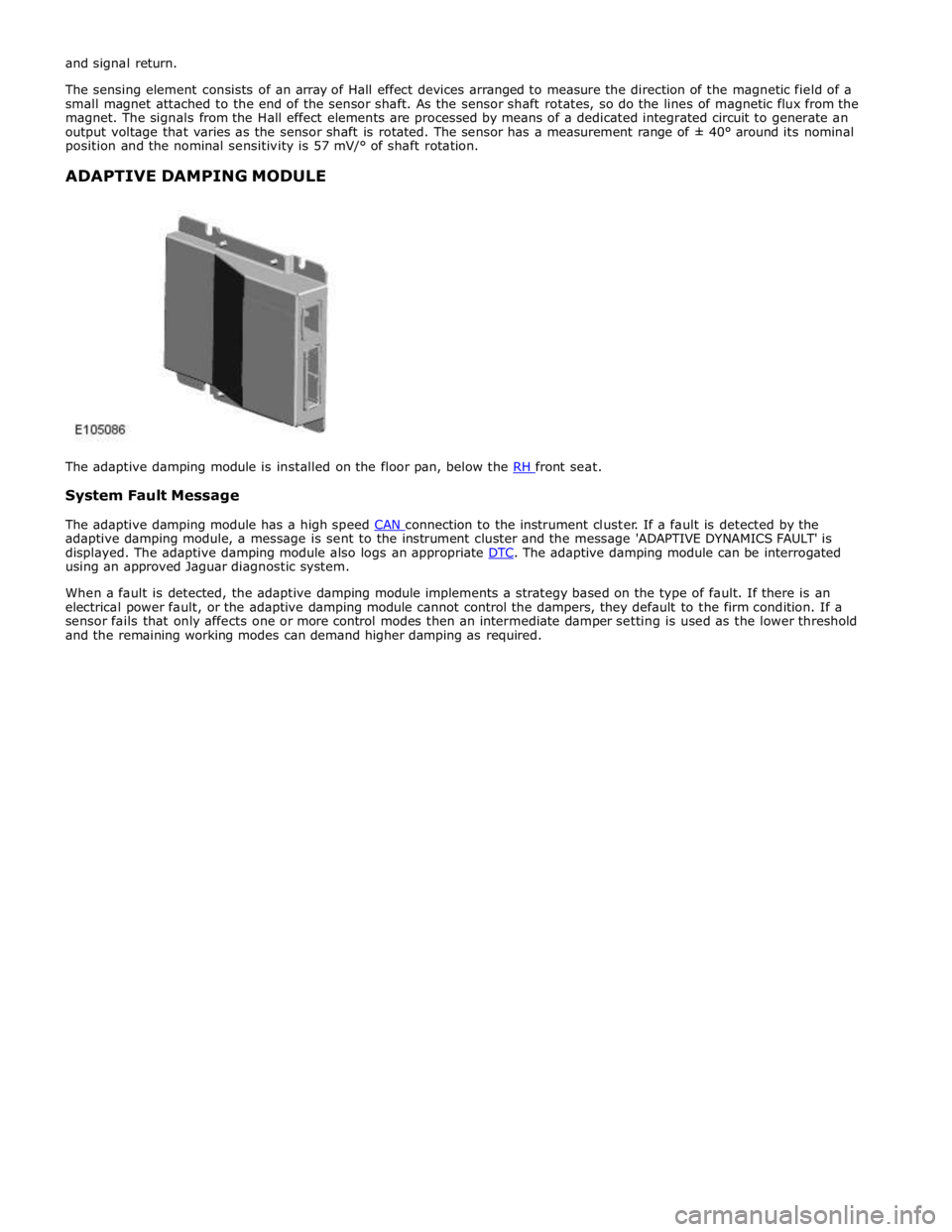
System Fault Message
The adaptive damping module has a high speed CAN connection to the instrument cluster. If a fault is detected by the adaptive damping module, a message is sent to the instrument cluster and the message 'ADAPTIVE DYNAMICS FAULT' is
displayed. The adaptive damping module also logs an appropriate DTC. The adaptive damping module can be interrogated using an approved Jaguar diagnostic system.
When a fault is detected, the adaptive damping module implements a strategy based on the type of fault. If there is an
electrical power fault, or the adaptive damping module cannot control the dampers, they default to the firm condition. If a
sensor fails that only affects one or more control modes then an intermediate damper setting is used as the lower threshold
and the remaining working modes can demand higher damping as required.
Page 488 of 3039

Vehicle Dynamic Suspension - Vehicle Dynamic Suspension
Diagnosis and Testing
Principle of Operation Published: 09-Jul-2014
For a detailed description of the adaptive damping system operation, refer to the relevant Description and Operation section of
the workshop manual. REFER to: (204-05 Vehicle Dynamic Suspension)
Vehicle Dynamic Suspension - V8 5.0L Petrol/V8 S/C 5.0L Petrol (Description and Operation),
Inspection and Verification
1. Verify the customer concern.
2. Visually inspect for obvious signs of damage and system integrity.
Visual Inspection
Mechanical Electrical
Coil spring(s)
Shock absorber(s)
Accelerometer(s) installation
Height sensor(s) installation
Fuse(s)
Wiring harness/electrical connectors
Accelerometer(s)
Adaptive Damping Control Module
Height sensor(s)
3. If an obvious cause for an observed or reported concern is found, correct the cause (if possible) before proceeding to
the next step.
4. If the cause is not visually evident, check the system for any logged Diagnostic Trouble Codes (DTCs) and refer to the
DTC index.
DTC Index
For a list of Diagnostic Trouble Codes (DTCs) that could be logged on this vehicle, please refer to Section 100-00.
REFER to: Diagnostic Trouble Code (DTC) Index - DTC: Adaptive Damping Module (SUMB) (100-00 General Information, Description and Operation).
Page 493 of 3039
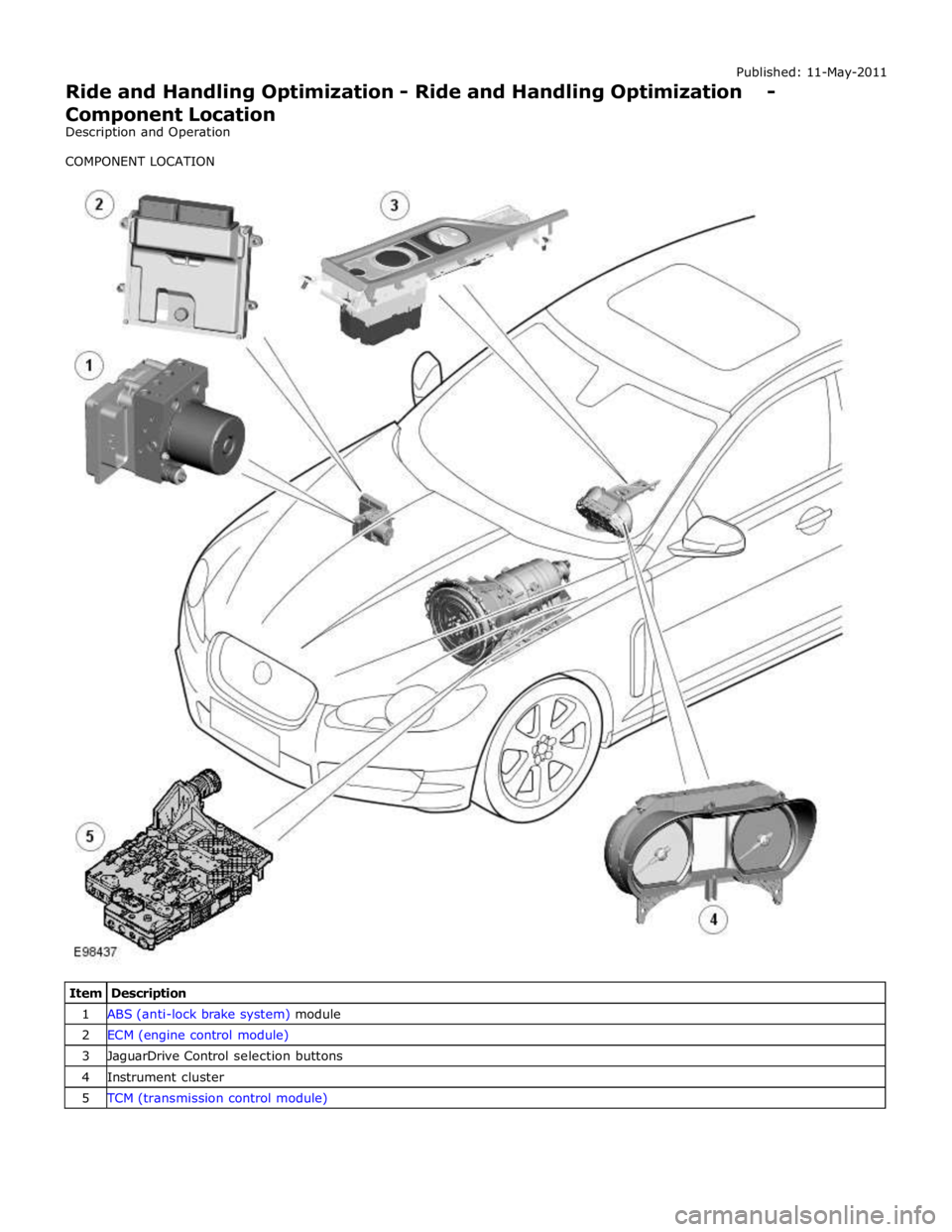
1 ABS (anti-lock brake system) module 2 ECM (engine control module) 3 JaguarDrive Control selection buttons 4 Instrument cluster 5 TCM (transmission control module)