sensor JAGUAR XFR 2010 1.G Workshop Manual
[x] Cancel search | Manufacturer: JAGUAR, Model Year: 2010, Model line: XFR, Model: JAGUAR XFR 2010 1.GPages: 3039, PDF Size: 58.49 MB
Page 1392 of 3039
Published: 11-May-2011
Electronic Engine Controls - V8 S/C 5.0L Petrol - Fuel Rail Pressure (FRP)
Sensor
Removal and Installation
Removal
NOTE: Removal steps in this procedure may contain installation details.
1. Refer to: Fuel System Pressure Release - V8 5.0L Petrol/V8 S/C 5.0L Petrol (310-00 Fuel System - General Information, General Procedures).
2. Disconnect the battery ground cable.
Refer to: Battery Disconnect and Connect (414-01 Battery, Mounting and Cables, General Procedures).
3. Refer to: Cowl Vent Screen (501-02 Front End Body Panels, Removal and Installation).
4. Refer to: Secondary Bulkhead Panel RH - TDV6 3.0L Diesel /V8 5.0L Petrol/V8 S/C 5.0L Petrol (501-02 Front End Body Panels, Removal and Installation).
5. Refer to: Secondary Bulkhead Panel LH - TDV6 3.0L Diesel /V8 5.0L Petrol/V8 S/C 5.0L Petrol (501-02 Front End Body Panels, Removal and Installation).
6. Refer to: Engine Cover - V8 5.0L Petrol/V8 S/C 5.0L Petrol (501-05 Interior Trim and Ornamentation, Removal and Installation).
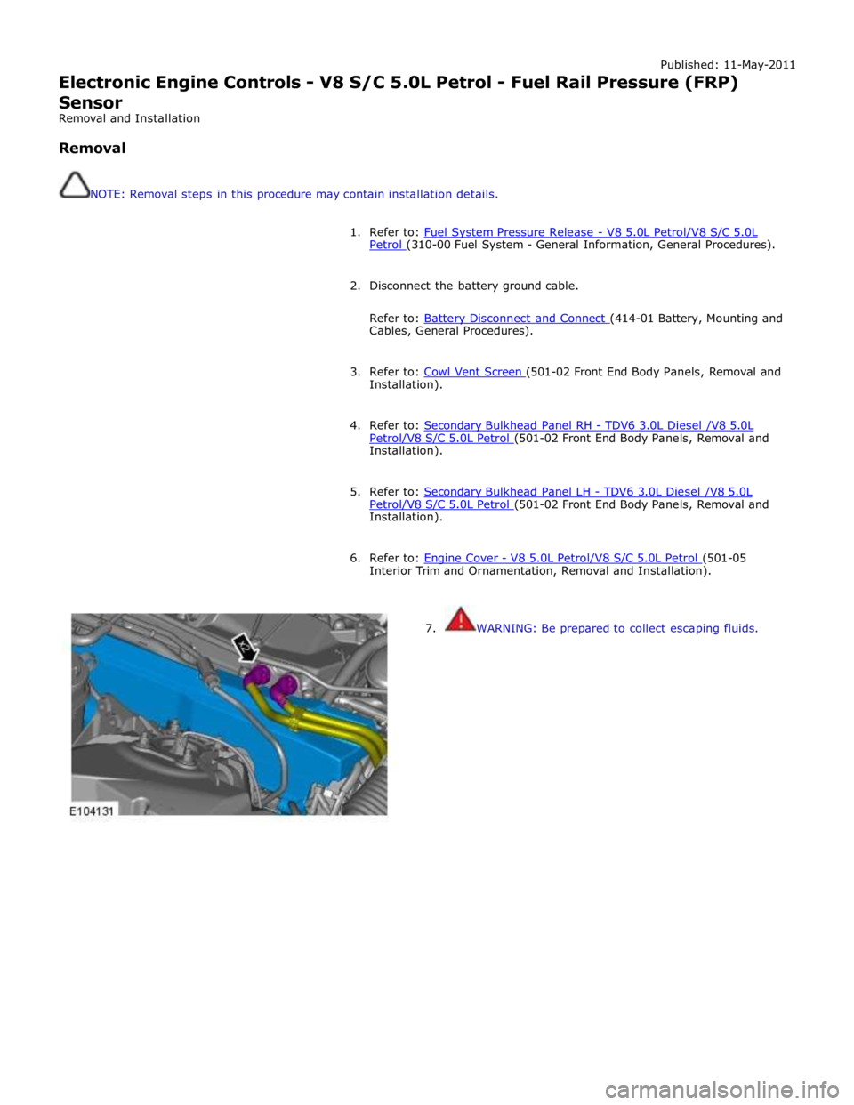
7. WARNING: Be prepared to collect escaping fluids.
Page 1394 of 3039
Published: 11-May-2011
Electronic Engine Controls - V8 S/C 5.0L Petrol - Heated Oxygen Sensor
(HO2S) LH
Removal and Installation
Removal
NOTE: Removal steps in this procedure may contain installation details.
1. Refer to: Battery Disconnect and Connect (414-01 Battery, Mounting and Cables, General Procedures).
2. WARNING: Do not work on or under a vehicle supported only by a jack.
Always support the vehicle on safety stands.
Raise and support the vehicle.
3. Refer to: Air Deflector (501-02 Front End Body Panels, Removal and Installation).
4. Refer to: Catalytic Converter LH (309-00C Exhaust System - V8 5.0L Petrol/V8 S/C 5.0L Petrol, Removal and Installation).
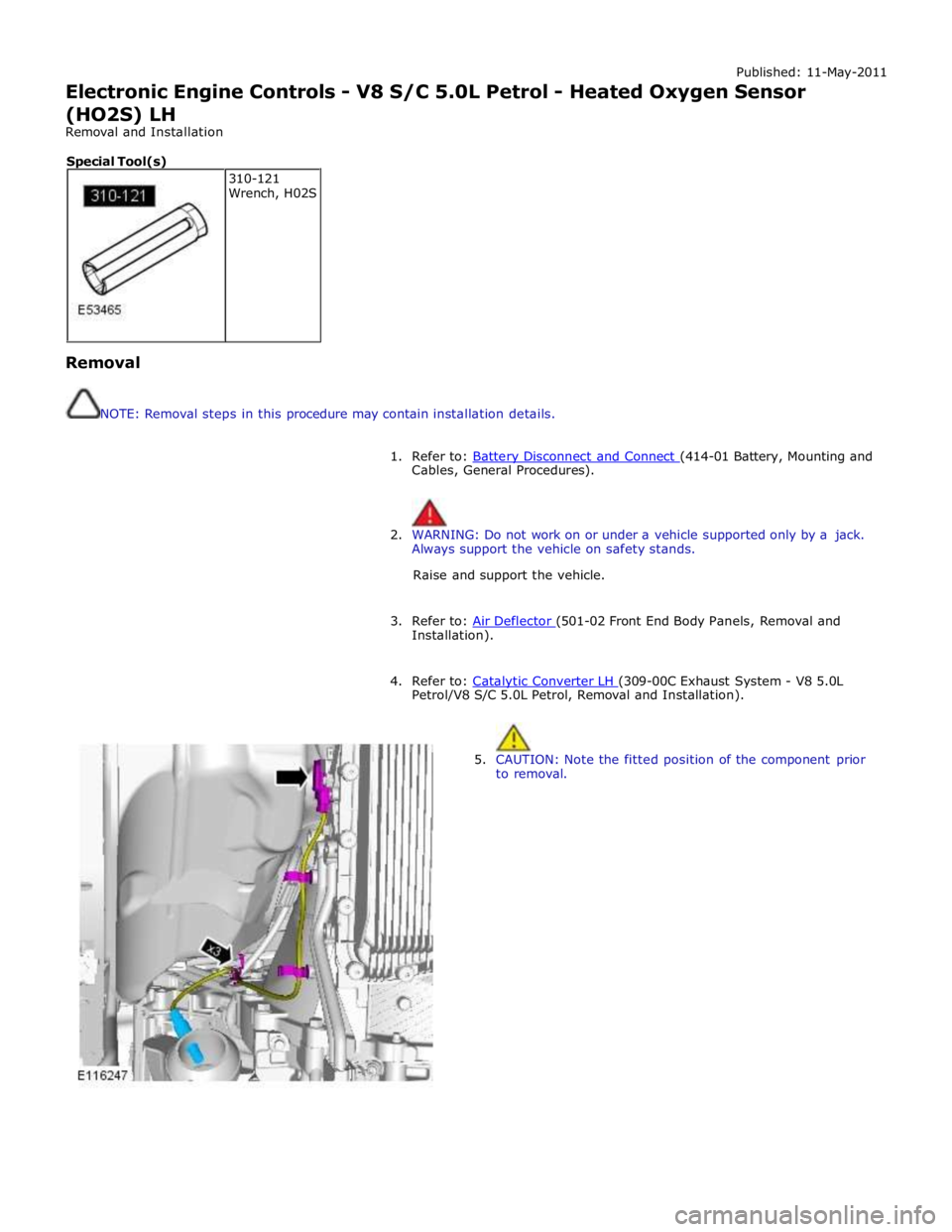
5. CAUTION: Note the fitted position of the component prior
to removal. 310-121
Wrench, H02S Special Tool(s)
Page 1395 of 3039

Installation 6. CAUTION: Make sure that the mating faces are clean
and free of foreign material.
Special Tool(s): 310-121 Torque: 48 Nm
1. CAUTIONS:
Make sure the anti-seize compound does not contact the HO2S tip.
If accidentally dropped or knocked install a new sensor.
Make sure the HO2S wiring harness is not twisted more than 180
degrees and is not in contact with either the exhaust or driveshaft.
NOTE: If the original sensor is to be installed, apply lubricant
meeting specification ESE-M12A4-A to the thread of the sensor.
To install, reverse the removal procedure.
2. NOTE: For NAS vehicles only.
If required, carry out a long drive cycle.
Refer to: Powertrain Control Module (PCM) Long Drive Cycle Self-Test (303-14D Electronic Engine Controls - V8 S/C 5.0L Petrol, General
Procedures).
Page 1396 of 3039
Published: 11-May-2011
Electronic Engine Controls - V8 S/C 5.0L Petrol - Heated Oxygen Sensor
(HO2S) RH
Removal and Installation
Removal
NOTE: Removal steps in this procedure may contain installation details.
1. Refer to: Battery Disconnect and Connect (414-01 Battery, Mounting and Cables, General Procedures).
2. WARNING: Do not work on or under a vehicle supported only by a jack.
Always support the vehicle on safety stands.
Raise and support the vehicle.
3. Refer to: Air Deflector (501-02 Front End Body Panels, Removal and Installation).
4. Refer to: Catalytic Converter RH (309-00C Exhaust System - V8 5.0L Petrol/V8 S/C 5.0L Petrol, Removal and Installation).
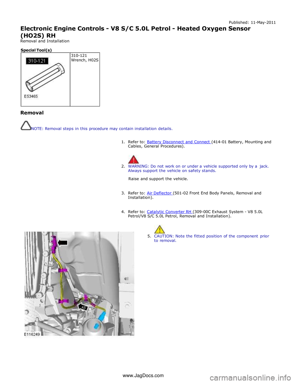
5. CAUTION: Note the fitted position of the component prior
to removal. 310-121
Wrench, H02S Special Tool(s) www.JagDocs.com
Page 1397 of 3039

Installation 6. CAUTION: Make sure that the mating faces are clean
and free of foreign material.
Special Tool(s): 310-121 Torque: 48 Nm
1. CAUTIONS:
Make sure the anti-seize compound does not contact the HO2S tip.
If accidentally dropped or knocked install a new sensor.
Make sure the HO2S wiring harness is not twisted more than 180
degrees and is not in contact with either the exhaust or driveshaft.
NOTE: If the original sensor is to be installed, apply lubricant
meeting specification ESE-M12A4-A to the thread of the sensor.
To install, reverse the removal procedure.
2. NOTE: For NAS vehicles only.
If required, carry out a long drive cycle.
Refer to: Powertrain Control Module (PCM) Long Drive Cycle Self-Test (303-14D Electronic Engine Controls - V8 S/C 5.0L Petrol, General
Procedures).
Page 1398 of 3039

Published: 11-May-2011
Electronic Engine Controls - V8 S/C 5.0L Petrol - Manifold Absolute Pressure
(MAP) Sensor
Removal and Installation
Removal
NOTE: Removal steps in this procedure may contain installation details.
1. Refer to: Engine Cover - V8 5.0L Petrol/V8 S/C 5.0L Petrol (501-05 Interior Trim and Ornamentation, Removal and Installation).
2. Refer to: Cowl Vent Screen (501-02 Front End Body Panels, Removal and Installation).
3. NOTE: Some variation in the illustrations may occur, but
the essential information is always correct.
Torque: 10 Nm
4. NOTE: Some variation in the illustrations may occur,
but the essential information is always correct.
Page 1401 of 3039
Published: 11-May-2011
Electronic Engine Controls - V8 S/C 5.0L Petrol - Mass Air Flow (MAF) Sensor
Removal and Installation
Removal
NOTE: Removal steps in this procedure may contain installation details.
1. Refer to: Battery Disconnect and Connect (414-01 Battery, Mounting and Cables, General Procedures).
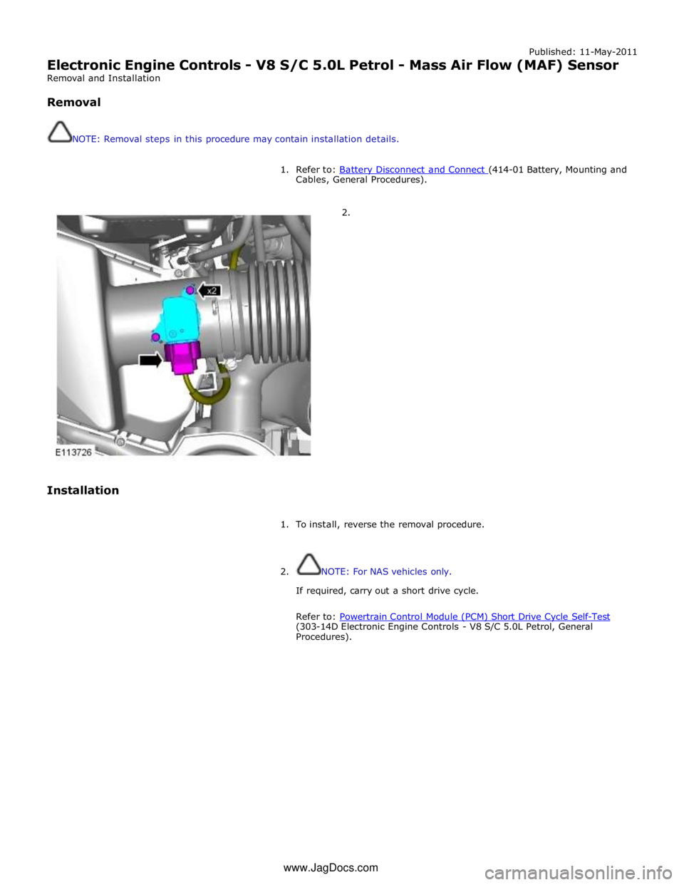
2.
Installation
1. To install, reverse the removal procedure.
2. NOTE: For NAS vehicles only.
If required, carry out a short drive cycle.
Refer to: Powertrain Control Module (PCM) Short Drive Cycle Self-Test (303-14D Electronic Engine Controls - V8 S/C 5.0L Petrol, General
Procedures). www.JagDocs.com
Page 1402 of 3039
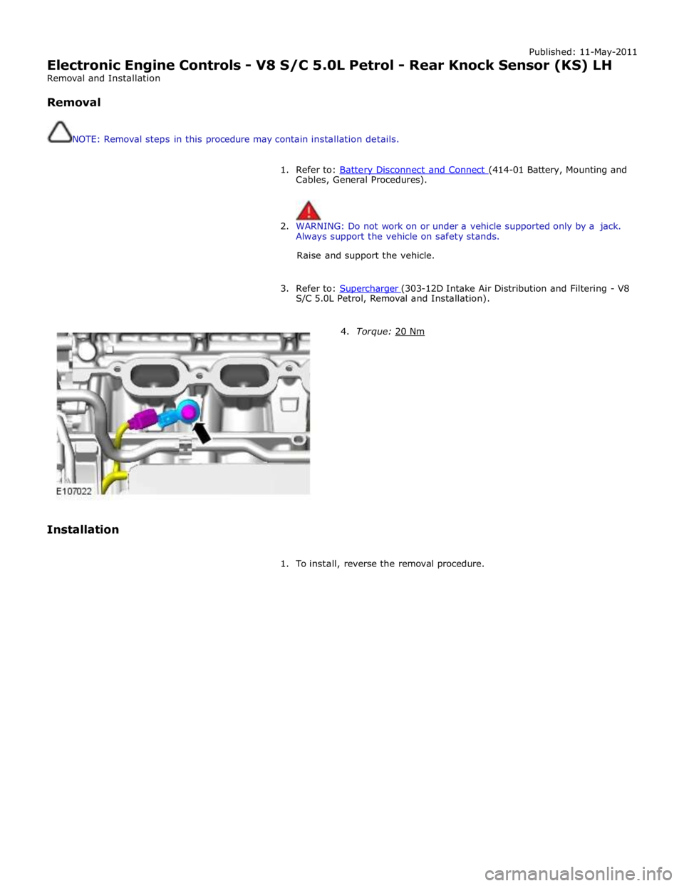
Published: 11-May-2011
Electronic Engine Controls - V8 S/C 5.0L Petrol - Rear Knock Sensor (KS) LH
Removal and Installation
Removal
NOTE: Removal steps in this procedure may contain installation details.
1. Refer to: Battery Disconnect and Connect (414-01 Battery, Mounting and Cables, General Procedures).
2. WARNING: Do not work on or under a vehicle supported only by a jack.
Always support the vehicle on safety stands.
Raise and support the vehicle.
3. Refer to: Supercharger (303-12D Intake Air Distribution and Filtering - V8 S/C 5.0L Petrol, Removal and Installation).
Installation
4. Torque: 20 Nm
1. To install, reverse the removal procedure.
Page 1403 of 3039
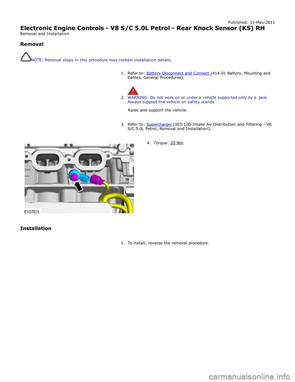
Published: 11-May-2011
Electronic Engine Controls - V8 S/C 5.0L Petrol - Rear Knock Sensor (KS) RH
Removal and Installation
Removal
NOTE: Removal steps in this procedure may contain installation details.
1. Refer to: Battery Disconnect and Connect (414-01 Battery, Mounting and Cables, General Procedures).
2. WARNING: Do not work on or under a vehicle supported only by a jack.
Always support the vehicle on safety stands.
Raise and support the vehicle.
3. Refer to: Supercharger (303-12D Intake Air Distribution and Filtering - V8 S/C 5.0L Petrol, Removal and Installation).
Installation
4. Torque: 20 Nm
1. To install, reverse the removal procedure.
Page 1422 of 3039
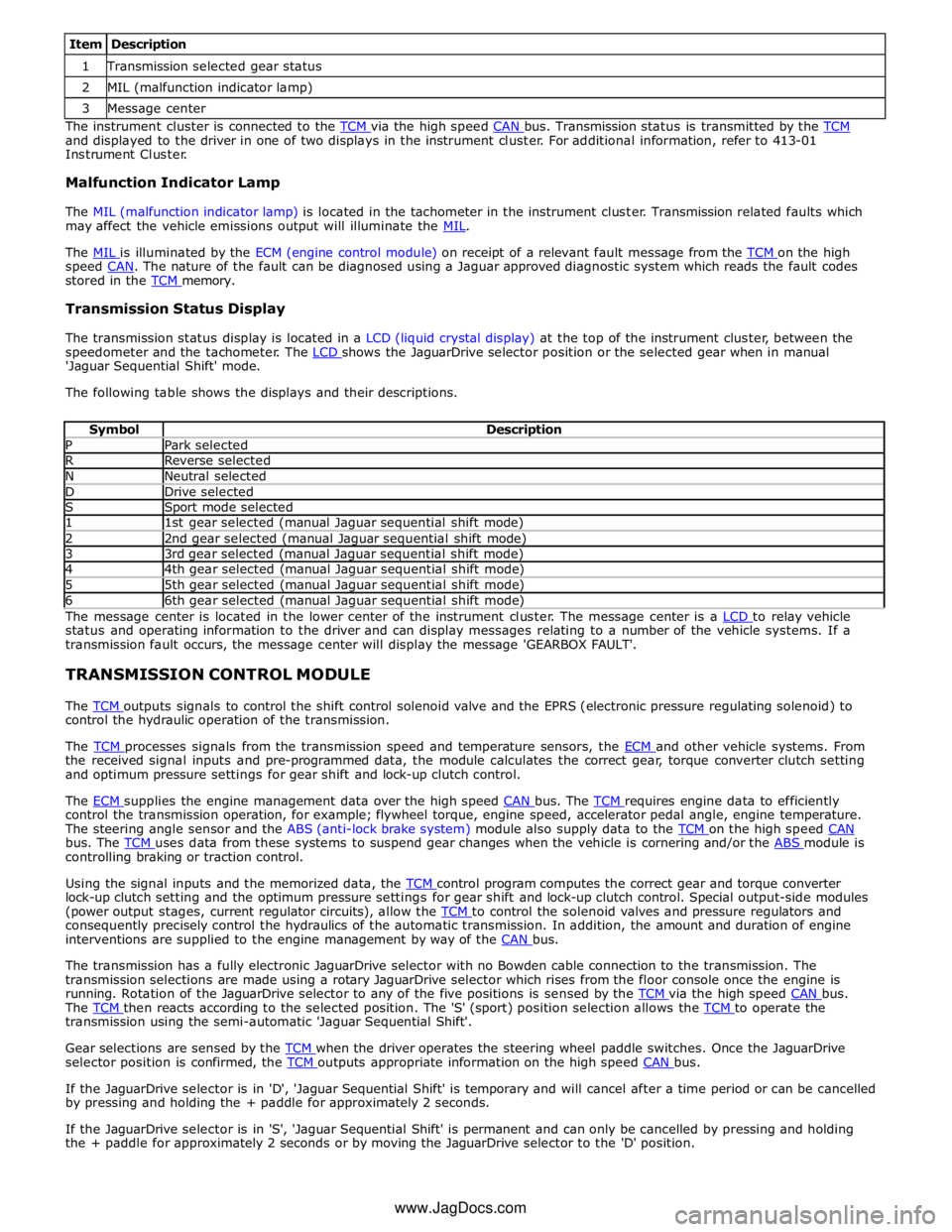
1 Transmission selected gear status 2 MIL (malfunction indicator lamp) 3 Message center The instrument cluster is connected to the TCM via the high speed CAN bus. Transmission status is transmitted by the TCM and displayed to the driver in one of two displays in the instrument cluster. For additional information, refer to 413-01
Instrument Cluster.
Malfunction Indicator Lamp
The MIL (malfunction indicator lamp) is located in the tachometer in the instrument cluster. Transmission related faults which
may affect the vehicle emissions output will illuminate the MIL.
The MIL is illuminated by the ECM (engine control module) on receipt of a relevant fault message from the TCM on the high speed CAN. The nature of the fault can be diagnosed using a Jaguar approved diagnostic system which reads the fault codes stored in the TCM memory.
Transmission Status Display
The transmission status display is located in a LCD (liquid crystal display) at the top of the instrument cluster, between the
speedometer and the tachometer. The LCD shows the JaguarDrive selector position or the selected gear when in manual 'Jaguar Sequential Shift' mode.
The following table shows the displays and their descriptions.
Symbol Description P Park selected R Reverse selected N Neutral selected D Drive selected S Sport mode selected 1 1st gear selected (manual Jaguar sequential shift mode) 2 2nd gear selected (manual Jaguar sequential shift mode) 3 3rd gear selected (manual Jaguar sequential shift mode) 4 4th gear selected (manual Jaguar sequential shift mode) 5 5th gear selected (manual Jaguar sequential shift mode) 6 6th gear selected (manual Jaguar sequential shift mode) The message center is located in the lower center of the instrument cluster. The message center is a LCD to relay vehicle status and operating information to the driver and can display messages relating to a number of the vehicle systems. If a
transmission fault occurs, the message center will display the message 'GEARBOX FAULT'.
TRANSMISSION CONTROL MODULE
The TCM outputs signals to control the shift control solenoid valve and the EPRS (electronic pressure regulating solenoid) to control the hydraulic operation of the transmission.
The TCM processes signals from the transmission speed and temperature sensors, the ECM and other vehicle systems. From the received signal inputs and pre-programmed data, the module calculates the correct gear, torque converter clutch setting
and optimum pressure settings for gear shift and lock-up clutch control.
The ECM supplies the engine management data over the high speed CAN bus. The TCM requires engine data to efficiently control the transmission operation, for example; flywheel torque, engine speed, accelerator pedal angle, engine temperature.
The steering angle sensor and the ABS (anti-lock brake system) module also supply data to the TCM on the high speed CAN bus. The TCM uses data from these systems to suspend gear changes when the vehicle is cornering and/or the ABS module is controlling braking or traction control.
Using the signal inputs and the memorized data, the TCM control program computes the correct gear and torque converter lock-up clutch setting and the optimum pressure settings for gear shift and lock-up clutch control. Special output-side modules
(power output stages, current regulator circuits), allow the TCM to control the solenoid valves and pressure regulators and consequently precisely control the hydraulics of the automatic transmission. In addition, the amount and duration of engine
interventions are supplied to the engine management by way of the CAN bus.
The transmission has a fully electronic JaguarDrive selector with no Bowden cable connection to the transmission. The
transmission selections are made using a rotary JaguarDrive selector which rises from the floor console once the engine is
running. Rotation of the JaguarDrive selector to any of the five positions is sensed by the TCM via the high speed CAN bus. The TCM then reacts according to the selected position. The 'S' (sport) position selection allows the TCM to operate the transmission using the semi-automatic 'Jaguar Sequential Shift'.
Gear selections are sensed by the TCM when the driver operates the steering wheel paddle switches. Once the JaguarDrive selector position is confirmed, the TCM outputs appropriate information on the high speed CAN bus.
If the JaguarDrive selector is in 'D', 'Jaguar Sequential Shift' is temporary and will cancel after a time period or can be cancelled
by pressing and holding the + paddle for approximately 2 seconds.
If the JaguarDrive selector is in 'S', 'Jaguar Sequential Shift' is permanent and can only be cancelled by pressing and holding
the + paddle for approximately 2 seconds or by moving the JaguarDrive selector to the 'D' position.
www.JagDocs.com